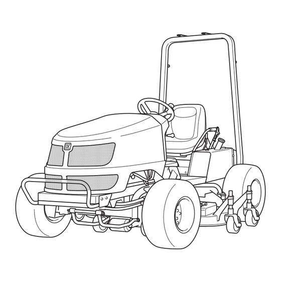
Baroness GM1700 Owner's Operating Manual
Mid-mount rotary mower
Hide thumbs
Also See for GM1700:
- Service manual (192 pages) ,
- Owner's operating manual (87 pages) ,
- Owner's operating manual (51 pages)

Subscribe to Our Youtube Channel
Related Manuals for Baroness GM1700


Summary of Contents for Baroness GM1700
- Page 1 Mid-Mount Rotary Mower Owner's Operating Manual Serial No. GM1700:21241- "Required reading" Read this manual before using the machine. Ver.2.1...
- Page 2 GM1700 Greeting Thank you for purchasing the Baroness product. This manual describes the proper handling, adjustment, and inspection of your product. We hope you will use the product safely, and take advantage of its best performance. For details on the handling, adjustment and inspection of the attachments, refer to the Owner's Operating Manual for the attachments.
-
Page 3: Warning Symbols
The operator is responsible for operating the product properly and safely. Maintenance service for this machine should be performed by a mechanic with expertise. If you have any questions concerning maintenance or genuine parts, please contact a Baroness dealer or Kyoeisha. -
Page 4: Precautionary Statement
When replacing parts, be sure to use genuine Baroness parts or parts designated by Kyoeisha. Note that the Baroness product warranty may not apply to defects caused by the use of parts from other companies. Prior to use, carefully read the following manuals to thoroughly understand the contents for safe and correct operation. -
Page 5: Table Of Contents
GM1700 Contents Safety .............. Page 1-1 Storage ............Page 6-19 Repair ..............Page 7-1 Safe Operating Practices .......Page 1-2 Disposal ............Page 2-1 Precautions for Repair ........Page 7-2 Adjustment and Replacement ......Page 7-2 Recycle and Waste Disposal ......Page 2-2 Towing ............ - Page 6 GM1700 Contents...
-
Page 7: Safety
GM1700 Safety Safe Operating Practices ...... Page 1-2 Training ..........Page 1-2 Preparation ..........Page 1-2 Operation ..........Page 1-3 Maintenance .......... Page 1-4 Storage ..........Page 1-5 Page 1-1... -
Page 8: Safe Operating Practices
GM1700 Safety Failure to adequately follow these safety Never allow children or people unfamiliar precautions may cause an accident resulting in with these instructions to use or service the injury or death. machine. Local regulations may restrict the age of the... -
Page 9: Operation
GM1700 Safety Add fuel before starting the engine. Never operate the machine with damaged Never remove the cap of the fuel tank or guards, shields, or without safety protective add fuel while the engine is running or devices in place. -
Page 10: Maintenance
GM1700 Safety Do the following before leaving the Take care when loading or unloading the operator's position. machine into a trailer or a truck. Load or unload the machine in a flat and Stop on level ground. safe place. Disengage the all drives. -
Page 11: Storage
GM1700 Safety Keep hands and feet away from moving If the fuel tank has to be drained, do this parts. outdoors. If possible, do not make adjustments with the Storage engine running. When machine is to be parked, stored, or left... - Page 12 GM1700 Safety Page 1-6 Safe Operating Practices...
-
Page 13: Disposal
GM1700 Disposal Recycle and Waste Disposal ....Page 2-2 About Recycle ........Page 2-2 About Waste Disposal ......Page 2-2 Page 2-1... -
Page 14: Recycle And Waste Disposal
GM1700 Disposal Recycle and Waste Disposal About Recycle Recycling battery etc. is recommended for environmental conservation and economical use of resources. It may be required by local laws. About Waste Disposal Make sure that waste generated when servicing or repairing the machine is disposed of in accordance with local regulations. -
Page 15: Product Overview
GM1700 Product Overview Specifications ........Page 3-2 Specifications .........Page 3-2 Sound Pressure Level ......Page 3-3 Sound Pressure Level ......Page 3-3 Sound Power Level ........Page 3-3 Sound Power Level ....... Page 3-3 Vibration Level ........Page 3-3 Hand-Arm Vibration ....... Page 3-3 Whole Body Vibration ...... -
Page 16: Specifications
GM1700 Product Overview Specifications Specifications Model GM1700 Name Mid-Mount Rotary Mower Total length 255 cm 100.39 in Total width 154 cm 60.63 in Dimensions Roof 190 cm 74.80 in Total height Steering wheel 121 cm 47.64 in Machine Weight (empty fuel... -
Page 17: Sound Pressure Level
GM1700 Product Overview Engine plug The factory default maximum engine rpm is 2,800 rpm. Sound Pressure Level Sound Pressure Level This machine was confirmed to have a continuous A-weighted sound pressure level of 93dB by measuring identical machines in accordance with the procedure specified in ISO 5395-1:2013. -
Page 18: Names Of Each Section
GM1700 Product Overview Names of Each Section Regulation Decals Positions of Regulation Decals quwxcl-158 Positions of Regulation Decals_001 quwxcl-157 Names of Each Section_001 Hood Steering wheel Seat 2WD/4WD selector lever Fuel tank quwxcl-159 Brake pedal Positions of Regulation Decals_002 Front wheel... -
Page 19: Regulation Decals
GM1700 Product Overview Description of Regulation Decals Serial Number Plate The serial number plate indicates the model and serial number of the machine. 4ogipb-001 Serial Number Plate_001 ROPS Compliance Decal The ROPS compliance decal indicates the manufacturer, model, etc., in accordance with International Standard ISO 21299:2009. -
Page 20: Safety Signs And Instruction Signs
0E5F2D3C Positions of Safety Decals and Instruction Decals_002 Part numbers for decals that need to be replaced are listed in the parts catalog. Order them from a Baroness dealer or Kyoeisha. Positions of Safety Decals and Instruction Decals 6iul4h-016... -
Page 21: Description Of Safety Decals And Instruction Decals
GM1700 Product Overview Description of Safety Decals and Fire Prohibited Decal Instruction Decals K4205001940 Caution to Hot Parts Decal Decal, fire prohibited Warning K4205001540 Decal for caution to hot parts Keep away from fire. Caution High temperature - Do not touch. Otherwise, you will get burned. - Page 22 GM1700 Product Overview Handling Caution Decal Caution Slope Decal K4205002010 K4205002110 DECAL, CAUTION HANDLING DECAL, ATTENTION AT SLOPE Without ROPS: Danger Danger Rollover - Do not work on slopes of 25 degrees or more. When you descend a slope, drive at low speed.
- Page 23 GM1700 Product Overview Caution for High Temperatures Decal Caution to Injury Decal K4205001920 K4205001580 Decal, caution for high temperatures Decal, caution to injure Caution Caution High temperature - Do not touch. Otherwise, May pinch - There is a risk of being pinched.
- Page 24 GM1700 Product Overview PTO Caution Decal Prohibited Drive at Public Road Decal K4205002000 K4205001660 Decal, caution PTO Decal, not to drive at public road Warning Watch for rotating parts - Keep your hands away from the joints while the engine is running.
-
Page 25: Operation Decals
GM1700 Product Overview Operation Decals Knife rotation mark Engine rotation mark Positions of Operation Decals Mower deck up/down mark Key switch decal Parking brake decal Tilt steering decal 2WD - 4WD changeover decal BRAKE decal FORWARD decal BACKWARD decal Description of Operation Decals... - Page 26 GM1700 Product Overview Mower Deck Up/Down Mark Parking Brake Decal Mower deck up/down mark K4203001340 This indicates the Up/Down positions of the Parking brake decal mower deck. This shows how to lock and release the parking brake. D O W N...
- Page 27 GM1700 Product Overview 2WD - 4WD Changeover Decal BACKWARD Decal K4203001510 K4203001440 DECAL, LEVER CHANGING 2WD / 4WD Decal, BACKWARD This indicates 2WD/4WD changeover. This indicates backward travel. BACKWARD sdts98-004 kqca3e-002 2WD - 4WD Changeover Decal_001 BACKWARD Decal_001 BRAKE Decal...
- Page 28 GM1700 Product Overview Page 3-14 Operation Decals...
-
Page 29: Description Of Functions
GM1700 Description of Functions Throttle Lever .........Page 4-2 Mower Deck Up/Down Switch ....Page 4-2 Knife Rotation Lever ......Page 4-2 2WD/4WD Selector Lever ...... Page 4-3 Traveling Pedal ........Page 4-3 Brake Pedal ..........Page 4-3 Parking Brake Lever ......Page 4-4 Instruments on the Operation Panel ..Page 4-4... -
Page 30: Throttle Lever
GM1700 Description of Functions Throttle Lever The throttle lever is located in the operation panel and enables you to adjust the engine rpm. Move the throttle lever toward the "High speed" position to increase the engine rpm, and toward the "Low speed" position to reduce the rpm. -
Page 31: 2Wd/4Wd Selector Lever
GM1700 Description of Functions Knife rotation lever BACKWARD FORWARD Rotation Stop 2WD/4WD Selector Lever Caution When working on a slope, be sure to use the machine in 4WD. yo3h9x-005 The 2WD/4WD selector lever is located to the Traveling Pedal_001 left of the driver's seat. -
Page 32: Parking Brake Lever
GM1700 Description of Functions Parking Brake Lever Water temperature gauge Angle meter Caution Tachometer/Hour meter Pilot lamps (charge lamp, thermo-start Never park the machine on a slope. lamp, oil pressure lamp) Tachometer/Hour Meter Important The tachometer and hour meter are located in Be sure to release the parking brake before the operation panel. -
Page 33: Water Temperature Gauge
GM1700 Description of Functions Water Temperature Gauge Thermo-Start Lamp This instrument indicates the water The thermo-start lamp is the middle pilot lamp temperature inside the engine. located in the operation panel. If the water temperature gauge indicates a When the ignition key is set to the "GLOW"... -
Page 34: Safety Mechanisms
GM1700 Description of Functions Angle Meter Warning Buzzer The angle meter is located in the operation Overheat Warning Buzzer panel. Caution This instrument indicates the angle of the machine position. When the buzzer (intermittent tone) sounds, be sure to stop operation since the engine is overheated. -
Page 35: Handling Instructions
GM1700 Handling Instructions Pre-installation Adjustments ....Page 5-2 Parking and Stopping ......Page 5-17 Installation of Attachments ....Page 5-2 Leaving The Machine ......Page 5-17 Installation of Universal Joint ....Page 5-2 Move ............Page 5-17 Operations Before Service ....Page 5-2 Traveling Procedure ...... -
Page 36: Pre-Installation Adjustments
GM1700 Handling Instructions Pre-installation Adjustments Operations Before Service Installation of Attachments The following sections describe the preparatory works required before performing the services For details on installing the attachment, please including inspection, adjustment, cleaning. refer to the separate attachment's Operating maintenance and repair. -
Page 37: Removing And Installing Of Rear Cover
GM1700 Handling Instructions Installing procedure: Hood support rod Bring the seat to the most front position. Secure Install the rear cover with the bolts. Release Removing and Installing of Center Cover To close the hood, release the hood support rod, and then lower the hood slowly. -
Page 38: Inspection And Cleaning
GM1700 Handling Instructions Removing and Installing of Underseat Hood Cover Inspection of Hood (Intake) Caution Make sure that there is no damage to the hood. Be careful not to pinch your fingers when you Make sure that the intake is not dirty. -
Page 39: Radiator
GM1700 Handling Instructions Radiator Hood Dust screen Inspection of Radiator Radiator Make sure that there is no damage to the Air intake radiator. Carefully clean the front and back of the Make sure that the radiator is not dust screen and radiator with water or contaminated. -
Page 40: Hydraulic Oil
GM1700 Handling Instructions Coolant Supply Reserve tank Reserve tank cap Caution If no coolant is in the reserve tank, follow Do not touch the radiator or coolant during the steps below to fill the tank with clean engine operation or right after the engine has water. - Page 41 GM1700 Handling Instructions Hydraulic Oil Supply Important Do not mix different types of oil. Important Use Shell Tellus S2M46 (or equivalent) as hydraulic oil. In case of an equivalent, consult 77F01897 Characteristics of Hydraulic Oil and use Hydraulic Oil Supply_001...
-
Page 42: Hydraulic Hoses
GM1700 Handling Instructions Check underneath the machine for oil leakage. Hydraulic Hoses Inspection of Hydraulic Hoses and Pipes Warning When checking the hydraulic circuit for pinhole leaks or oil leakage from nozzles, do not use your hands. Use items such as paper... -
Page 43: Battery
GM1700 Handling Instructions Inspecting the mounting bracket Air cleaner element Inspect whether the battery is secured Clip firmly with the mounting bracket. Air cleaner cap If the bracket is loose, tighten the mounting Air cleaner body bracket nuts until the battery is secured firmly. -
Page 44: Electrical Wiring
GM1700 Handling Instructions If the battery fluid level is lower than halfway between the UPPER LEVEL (maximum fluid level line) and LOWER LEVEL (minimum fluid level line), add purified water. U P P E R L E V E L L O W E R L E V E L Loosen the vent plug and remove it. -
Page 45: Tire
GM1700 Handling Instructions Tire Belt Inspection of Tires Inspection of Belt Check the pneumatic pressure of the tires. Warning Make sure that there are no cracks, The engine must be stopped when the belt is damage or abnormal wear. inspected. -
Page 46: Around The Engine
GM1700 Handling Instructions Position the machine so that the engine will Around The Engine be level, then insert the oil gauge all the way to check the oil level. Inspection of Engine-Associated Parts Caution Perform operations after the engine and other parts have sufficiently cooled. -
Page 47: Fuel
GM1700 Handling Instructions Fuel Supply of Engine Oil Inspection of Fuel Quantity Important Position the machine so it is level, and then Do not supply too much engine oil. Otherwise, observe the fuel gauge located on the fuel the engine may be damaged. -
Page 48: Fuel Filter
GM1700 Handling Instructions Check for unequal bolt length. Fuel tank Check the bolts and nuts for stripped Tank cap threads and abrasion. Fuel gauge Inspection of Wheel Mounting Bolt Fuel Filter Important Inspection of Fuel Filter Tighten the wheel mounting bolts on the Make sure that there is no fuel leakage. -
Page 49: Adjustment Before Work
GM1700 Handling Instructions Use the adjustment lever to adjust the seat Adjustment before Work back and forth. Adjust the position according to the Adjustment of Steering Wheel Position operator's body size. The adjustment lever is located beneath the Warning front part of the seat. -
Page 50: Start/Stop Of Engine
GM1700 Handling Instructions Shift the throttle lever halfway from the "Low Start/Stop of Engine speed" position toward the "High speed" position. Procedure to Start Engine Important Caution The thermo-start lamp turns off at the Before starting the engine, make sure that specified time. -
Page 51: Parking And Stopping
GM1700 Handling Instructions Parking and Stopping Important Quickly returning the ignition key from the Leaving The Machine "START" position to the "ON" position may result in damage to the machine. Caution After the thermo-start lamp turns off, If the brakes are not sufficiently effective, use immediately set the ignition key to the the wheel stoppers to secure the machine. -
Page 52: Cutting Work
GM1700 Handling Instructions Cutting Work Cutting Operation Caution Cutting work must be performed at an appropriate speed for the site and location. When cutting bumpy surfaces, keep the engine rpm steady, and slow down the cutting speed. Caution All persons other than the operator must keep a safe distance from the machine. -
Page 53: Maintenance
GM1700 Maintenance Precautions for Maintenance ....Page 6-2 Jacking Up The Machine .......Page 6-2 About Jacking Up The Machine .....Page 6-2 Jack-Up Points ........Page 6-2 Greasing ..........Page 6-3 About Greasing ........Page 6-3 Greasing Points ........Page 6-4 Lubrication ..........Page 6-6 About Lubrication ........Page 6-6... -
Page 54: Precautions For Maintenance
First, learn well the operations you plan to perform. Important Use tools appropriate for each operation. Important Use Baroness genuine parts for replacement and accessories. Our product warranty may be void if you use non-genuine parts for replacement or accessories. -
Page 55: Greasing
GM1700 Maintenance Front right frame Rear left frame rwyt62-048 rwyt62-052 Jack-Up Points_002 Jack-Up Points_006 Front left frame Greasing About Greasing Since there may be adhesion or damage due to lack of grease on moving parts, they must be greased. Add urea-based No. 2 grease in accordance with the Maintenance Schedule. -
Page 56: Greasing Points
GM1700 Maintenance Pivot Greasing Points Jack up the machine and apply grease. Grease nipples are installed in the following Middle between the front wheels locations. Add grease every 50 hours of operation. 8bq62b-129 Greasing Points_002 Front right wheel 8bq62b-130 Greasing Points_003... - Page 57 GM1700 Maintenance Knife rotation lever fulcrum Traveling pedal shaft fulcrum Forward pedal 8bq62b-132 Greasing Points_005 8bq62b-135 Brake pedal shaft fulcrum Greasing Points_008 Reverse pedal 8bq62b-133 Greasing Points_006 8bq62b-136 Chain wheel mounting shaft fulcrum Greasing Points_009 One greasing point is provided to each of the...
-
Page 58: Lubrication
GM1700 Maintenance Joint fulcrum Cam lever shaft fulcrum One greasing point is provided to each of the two fulcrums of the joint. 8bq62b-141 Greasing Points_014 8bq62b-138 Seat mounting bracket Greasing Points_011 Joint connector 8bq62b-142 Greasing Points_015 8bq62b-139 Lubrication Greasing Points_012... -
Page 59: Lubricating Points
GM1700 Maintenance Lubricating Points Apply lubricant at the following locations every 50 hours of operation. 9llqa9-047 Lubricating Points_003 Mower up/down cylinder spherical bearing There are two points. 9llqa9-048 Lubricating Points_004 9llqa9-045 Lubricating Points_001 No. of Location lubricating points Steering cylinder spherical... -
Page 60: Adjustment And Replacement
GM1700 Maintenance Adjustment and Replacement Replacement of Rear Tires Removing rear tires Replacement of Tires Follow the steps below to remove the rear Replacement of Front Tires tires: Loosen the bolts. Removing front tires Follow the steps below to remove the front tires: Loosen the bolts. -
Page 61: Adjustment Of Belt Tension
GM1700 Maintenance Be sure to tighten bolt A, nut and bolt B Adjustment of Belt Tension securely after adjustment. Warning Be sure to stop the engine before adjusting the belts. Important For the specified value of belt tension, refer to Adjusted Values. - Page 62 GM1700 Maintenance Be sure to tighten bolt A, nut and bolt B Set the knife rotation lever to the "Rotation" securely after adjustment. position, and then press the middle of the belt with your finger to check the belt tension.
-
Page 63: Change Of Coolant
GM1700 Maintenance Tension return spring ・ Important Set the knife rotation lever to the "Stop" position, and then adjust the tension When changing the coolant, be sure to mix return spring so that it has no tension and clean water and antifreeze (long-life coolant), no play. - Page 64 GM1700 Maintenance Remove the radiator cap. Stop the engine, and then allow the radiator to cool. Check if the coolant level in the reserve tank is between "FULL" and "LOW", and then supply coolant if necessary. Close the hood. ouuoov-008...
-
Page 65: Change Of Hydraulic Oil
GM1700 Maintenance Remove the drain plug of the hydraulic Change of Hydraulic Oil tank, and then drain the old oil into a container. Caution Wind new sealing tape on the drain plug, Be careful with hot oil, which could cause and then attach it to the hydraulic tank. -
Page 66: Change Of Hydraulic Oil Filter
GM1700 Maintenance Install the oil filler plug and tighten the Important bushing securely. Use Shell Tellus S2M46 (or equivalent) as hydraulic oil. Move the machine onto a level surface and stop the engine. Remove the bolt fixing the filter guard and then the filter guard. -
Page 67: Replacement Of Air Breather Element
GM1700 Maintenance Install the new element. Replacement of Air Breather Element Important Caution If the seal washer is damaged, replace it with a new one. Be careful with hot oil, which could cause burns if it contacts your skin. Install the top cover of the air breather. -
Page 68: Change Of Engine Oil
GM1700 Maintenance Through the oil filling port, supply new Change of Engine Oil engine oil until the oil reaches a level in between the upper and lower limit lines on Caution the oil level gauge. Engine oil quantity is approximately 3.0 dm Be careful with hot oil, which could cause (3.0 L). -
Page 69: Replacement Of Engine Oil Filter
GM1700 Maintenance Make sure that there is no oil leakage at the Replacement of Engine Oil Filter sealing surface of the filter cartridge. Check the engine oil level. Caution If it is low, supply engine oil until it reaches Be careful with hot oil, which could cause the specified level. -
Page 70: Change Of Transmission Oil
GM1700 Maintenance O-ring Important Element When you change the transmission oil, be sure to drain it into a bowl and discard it in Ring nut accordance with regional laws and regulations. Clean the inside of the filter cup with diesel fuel. -
Page 71: Storage
GM1700 Maintenance Storage Long-Term Storage Follow the instructions below for long-term storage of the machine. Cleaning Remove dirt, grass clippings, oil stains etc. ・ completely from the main vehicle and engine. Replacing oil Inspect and replace the engine oil, ・... - Page 72 GM1700 Maintenance Page 6-20 Storage...
-
Page 73: Repair
GM1700 Repair Precautions for Repair ......Page 7-2 Adjustment and Replacement ....Page 7-2 Adjustment of Brake ......Page 7-2 Adjusting the Neutral Position of the Piston Pump .......... Page 7-3 Change of Fuse ........Page 7-4 Towing ............ Page 7-5 Towing the Machine in An Emergency ..........Page 7-5... -
Page 74: Precautions For Repair
Start the engine and drive to check the following. Important Make sure that heat is not generated in ・ Use Baroness genuine parts for replacement the brake area. and accessories. Make sure that the left and right brakes ・ Our product warranty may be void if you use are equally effective. -
Page 75: Adjusting The Neutral Position Of The Piston Pump
GM1700 Repair Adjusting the Neutral Position of the Piston Cam lever Pump Cam lever shaft Shaft seat Caution Lock nut A Threaded rod Make sure not to touch rotating tires. Lock nut B (right-hand thread) If the machine moves forward or backward... -
Page 76: Change Of Fuse
GM1700 Repair Change of Fuse Important A B C D E When performing maintenance on the electrical system, be sure to remove the F G H I J negative battery wire. Important If a fuse blows, a short may have occurred pkm25s-006 within the electrical circuit. -
Page 77: Towing
GM1700 Repair Turn the unload valves counterclockwise by Towing three to four rotations to loosen it. Towing the Machine in An Emergency 2WD: Loosen either one of the unload ・ valves. If the machine does not travel due to engine 4WD: Loosen both of the unload valves. - Page 78 GM1700 Repair Page 7-6 Towing...
-
Page 79: Appended Table
GM1700 Appended Table Tightening Torques ....... Page 8-2 Standard Tightening Torques ....Page 8-2 Principal Tightening Torques ....Page 8-5 Maintenance Schedule ......Page 8-6 List of Adjusted Values ......Page 8-7 Page 8-1... -
Page 80: Tightening Torques
GM1700 Appended Table Tightening Torques Important Refer to the Tightening Torque table. Note that the Baroness product warranty may not apply to defects caused by incorrect or overtorque tightening, etc. Standard Tightening Torques Bolts and Nuts Important A number of bolts are used in each part of this machine. - Page 81 GM1700 Appended Table General bolt Strength classification 4.8 Nominal diameter tib3yb-001 kgf-cm lb-in 3 - 5 30.59 - 50.99 26.55 - 44.26 7 - 9 71.38 - 91.77 61.96 - 79.66 14 - 19 142.76 - 193.74 123.91 - 168.17 29 - 38 295.71 - 387.49...
- Page 82 GM1700 Appended Table Hydraulic Hose The tightening torques for union joints and union adaptors with parallel pipe threads (G, PF) are shown in the table below. A union joint or adaptor will not become loose or leak as long as it is tightened by the specified torque.
-
Page 83: Principal Tightening Torques
GM1700 Appended Table Principal Tightening Torques Tightening Torque by Model GM1700_Main vehicle Tighten the following bolts and nuts at the torque specified in the table. For thread locking adhesive, apply a middle strength thread locker (ThreeBond 1322 or equivalent anaerobic sealant). -
Page 84: Maintenance Schedule
GM1700 Appended Table Maintenance Schedule GM1700 (Main vehicle) ●・・・Inspect, adjust, supply, clean (first time) ○・・・Inspect, adjust, supply, clean ▲・・・Replace (first time) △・・・Replace Maintenance Item Remarks Tightening the parts ○ ... -
Page 85: List Of Adjusted Values
GM1700 Appended Table Maintenance Item Remarks Refer to "Change of Air Cleaner" Air cleaner ○ △ △ Every 200 hours or every year whichever comes earlier. Fuel strainer ○... - Page 86 GM1700 Appended Table Page 8-8 List of Adjusted Values...
- Page 87 1-26, Miyuki-cho, Toyokawa-city, Tel : +81 - 533 - 84 - 1390 Head Office Aichi-pref, 442-8530 JAPAN Fax : +81 - 533 - 84 - 1220 GM1700--UM--00Z/23K-00-S.K...
Need help?
Do you have a question about the GM1700 and is the answer not in the manual?
Questions and answers