KERN KFE-TM Operating And Installation Instructions
Display unit
Hide thumbs
Also See for KFE-TM:
- Manual (71 pages) ,
- Instruction manual (59 pages) ,
- Supplementary instructions manual (13 pages)
Table of Contents
Advertisement
Quick Links
See also:
Manual
Advertisement
Chapters
Table of Contents

Related Manuals for KERN KFE-TM


Summary of Contents for KERN KFE-TM
- Page 1 KERN & Sohn GmbH Ziegelei 1 Phone: +49-[0]7433- 9933-0 D-72336 Balingen Fax: +49-[0]7433-9933-149 E-Mail: info@kern-sohn.com Internet: www.kern-sohn.com Návod na obsluhu a inštaláciu(EN) KERN KFE/SFE nerezová váha pre potravinársky priemysel(SK) Version 1.3 06/2013 KFE-TM-BA_IA-e-1313...
-
Page 2: Table Of Contents
KERN KFE-TM Version 1.3 06/2013 Operating and installation instructions Display unit Contents Technical data ....................4 Appliance overview ................... 5 Keyboard overview ....................6 2.1.1 Numerical input via the navigation buttons ................ 7 Overview of display....................7 Basic Information (General) ................8 Proper use ......................... - Page 3 Instant help....................30 Installing display unit / weighing bridge............ 31 11.1 Technical data ......................31 11.2 Weighing system design...................31 11.3 How to connect the platform ..................32 11.4 Configure display unit ....................33 Enclosure Declaration of conformity / Type approval / Test certificate. 36 KFE-TM-BA_IA-e-1313...
-
Page 4: Technical Data
1 Technical data KERN KFE-TM Display 6-digit Solution verifiable 6.000 e Verification class Weighing ranges 1,2,5,…10, n Divisions Display LCD 22 mm digits with back lighting 80-100 . Max. 4 items per 350 DMS weighing cells Sensitivity 2-3 mV/V Input voltage 220 V – 240 V, 50 Hz... -
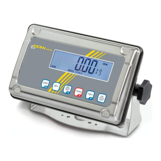
Page 5: Appliance Overview
2 Appliance overview Front view: 1. Weight display 2. Keyboard Rear view: 3. Wall bracket 4. Connection power supply (mains adapter) 5. Fastening screws 6. Connection platform 7. Position of seal / housing screw KFE-TM-BA_IA-e-1313... -
Page 6: Keyboard Overview
At numeric input increase flashing digit Add weighing value to summation memory Display sum total Delete total added memory Change between gross and net weight Navigation key Digit selection to the right Switch-over weighing unit Back to menu/weighing mode KFE-TM-BA_IA-e-1313... -
Page 7: Numerical Input Via The Navigation Buttons
The displayed weighing value is a net weighing value GROSS The displayed weighing value is a gross weighing value STABLE Stability display Function for „Automatic totalizing“ is activated AUTO ANIMAL Animal weighing mode is activated Charging status of rechargeable battery (optional) KFE-TM-BA_IA-e-1313... -
Page 8: Basic Information (General)
The display unit may only be operated in accordance with the described default settings. Other areas of use must be released by KERN in writing. 3.3 Warranty Warranty claims shall be voided in case... -
Page 9: Monitoring Of Test Resources
KERN’s home page (www.kern-sohn.com with regard to the monitoring of display units’ test substances and the test weights required for this. In KERN’s accredited DKD calibration laboratory test weights and display units may be calibrated (return to the national standard) fast and at moderate cost. -
Page 10: Unpacking And Installation
Mount the display unit in a way that facilitates operation and where it is easy to see. 6.3 Scope of delivery / serial accessories: For display unit, see chapter 2 Mains adapter Operating instructions KFE-TM-BA_IA-e-1313... -
Page 11: Transit Securing
6.5 Mains connection Power is supplied via the external mains adapter. The stated voltage value must be the same as the local voltage. Only use original KERN mains adapters. Using other makes requires consent by KERN. 6.6 Storage battery operation (optional) Before the first use, the battery should be charged by connecting it to the mains power supply for at least 12 hours. -
Page 12: Adjustment
The weight to be used depends on the capacity of the scale. Carry out adjustment as near as possible to the scale’s maximum weight. Info about test weights can be found on the Internet at: http://www.kern sohn.com. Observe stable environmental conditions. Stabilisation requires a certain warm-up time. - Page 13 displayed. = Singel range = Dual range = Multi interval Confirm by Press repeatedly until will be displayed. Confirm by and select by = Justierung = Linearisierung KFE-TM-BA_IA-e-1313...
- Page 14 After the adjustment the balance will carry out a self-test. Remove adjusting weight during selftest, balance will return into weighing mode automatically. An adjusting error or incorrect adjusting weight will be indicated by the error message; repeat adjustment procedure. KFE-TM-BA_IA-e-1313...
-
Page 15: Linearization
“LoAd 1“ is displayed, put the first adjustment weight (1/3 max) carefully in the centre of the weighing platform. Wait for stability display „STABLE“, then press . When “LoAd 2“ is displayed, put the second adjustment weight (2/3 max) carefully in the centre of the weighing platform. KFE-TM-BA_IA-e-1313... -
Page 16: Verification
The seal marks attached on verified balances point out that the balance may only be opened and serviced by trained and authorised specialist staff. If the seal mark is destroyed, verification looses its validity. Please observe all national laws and legal regulations. In Germany a re-verification will be necessary. KFE-TM-BA_IA-e-1313... -
Page 17: Kfe-Tm-Ba_Ia-E
Position of seals and jumper Access to conductor plate: Remove seal Open display unit For adjustment / access to the configuration menu the jumper „CAL“ must be fitted. KFE-TM-BA_IA-e-1313... -
Page 18: Operation
Overloading exceeding the stated maximum load (max) of the device, minus a possibly existing tare load, must be strictly avoided. This could damage the instrument. Exceeding maximum load is indicated by the display of “ol“, and an audio sound. Unload weighing system or reduce preload. KFE-TM-BA_IA-e-1313... -
Page 19: Weighing With Taring
[LO], [OK] or [HI] If load is within tolerance range, [ok] will be displayed bp 2 and audio signal will be sounded. If the load is beyond the tolerance range [ok] will be bp 3 shown and the audio signal will sound. KFE-TM-BA_IA-e-1313... - Page 20 Press the navigation keys (See chpt. 2.1.1) to enter the upper limit, e.g. 1,100 kg; the currently enabled digit will be flashing. Confirm input by Press and the unit will return to the menu KFE-TM-BA_IA-e-1313...
- Page 21 Load exceeds specified tolerance tolerance tolerance The indicator [LO] is The indicator [OK] is The indicator [HI] is displayed displayed displayed The tolerance control is not active when the weight is under 20d. To delete limits, enter “00.000 kg“. KFE-TM-BA_IA-e-1313...
-
Page 22: Manual Totalizing
You can repeat this process 99 times until the capacity (max) of the weighing system is exhausted. Display of the saved weighing data: When zero is displayed press , the number of weighings followed by the total weight will be displayed for 2 sec. KFE-TM-BA_IA-e-1313... - Page 23 Delete weighing data: If you see a display of zero, press and the number of weighing, followed by the total weight will be shown for 2 sec. Press during this display. The data in the summation memory are deleted. KFE-TM-BA_IA-e-1313...
-
Page 24: Automatic Adding-Up
You can repeat this process 99 times until the capacity (max) of the weighing system is exhausted. After the audio sound was sounded you can remove the load or add to it. Display and delete weighing data see chap. 7.7. KFE-TM-BA_IA-e-1313... -
Page 25: Animal Weighing
Whilst averaging is taking place you can add or remove loads as the measuring value will be constantly updated. To disable the animal weighing function, return to weighing mode Select menu setting , see chpt. 11.4. KFE-TM-BA_IA-e-1313... -
Page 26: Menu
To make changes, press the navigation keys as explained in chpt. 2.1.1. SET ti Set time Press and the currently set time (hh.m.ss) will be displayed. To make changes, press the navigation keys as explained in chpt. 2.1.1. KFE-TM-BA_IA-e-1313... - Page 27 Confirm selection by , after that the following menu items are available. b9600 Pr X Lab X Not documented Ty-tp Ty 711 Lp 50 St on Following tare ON St off Following tare OFF Access to configuration menu see chap. 11.4 KFE-TM-BA_IA-e-1313...
-
Page 28: Service, Maintenance, Disposal
Do not use metal brushes or cleaning sponges of steel wool, as this causes superficial corrosion. 9.2 Service, maintenance The appliance may only be opened by trained service technicians who are authorized by KERN. Ensure that the balance is regularly calibrated, see chap. Testing instruments control. 9.3 Disposal ... -
Page 29: Error Messages
Fai l h / Adjustment error Repeat adjustment. Fai l l Ba lo / Battery very low Recharge battery Lo ba Should other error messages occur, switch balance off and then on again. If the error message remains inform manufacturer. KFE-TM-BA_IA-e-1313... -
Page 30: Instant Help
The weighing result is The display of the balance is not at zero obviously incorrect Adjustment is no longer correct. Great fluctuations in temperature. Warm-up time was ignored. Electromagnetic fields / static charging (choose different location/switch off interfering device if possible) KFE-TM-BA_IA-e-1313... -
Page 31: Installing Display Unit / Weighing Bridge
4 % of the scale’s capacity. The addition of weighing scales capacity, preload and the total zero setting range give the required capacity for the weighing cell. To avoid overloading of the weighing cell, include an additional safety margin. Smallest desired display division KFE-TM-BA_IA-e-1313... -
Page 32: How To Connect The Platform
Pull load cell cable into the display unit through the screwable cable attachment. Weld the individual wires of the load cell cable to the printed circuit board, see fig. 1. Details can be seen in the technical data of the load cell. Fig. 1 KFE-TM-BA_IA-e-1313... -
Page 33: Configure Display Unit
, the individual menu items can be selected one after the other. Confirm selected menu item by pressing . The current setting will be displayed. Switch into the available settings using Either save by pressing or cancel by pressing Press repeatedly to exit menu. KFE-TM-BA_IA-e-1313... - Page 34 , after that the following menu items are available. Position decimal point available selection 0, 0.0, 0.00, 0.000, 0.0000 Readability/verification value selectable 1, 2, 5, 10, 20, 50 Balance capacity (max) Adjust weighing system according to configuration. Adjustment, see chap. 6.7 For linearisation see chapter 6.8 KFE-TM-BA_IA-e-1313...
- Page 35 Readability / verification value for 2. Weighing range Selectable 1, 2, 5, 10, 20, Balance capacity (Max) 1st weighing range Balance capacity (Max) 2nd weighing range Adjust weighing system according to configuration. Adjustment, see chap. 6.7 For linearisation see chap. 6.8 KFE-TM-BA_IA-e-1313...
-
Page 36: Enclosure Declaration Of Conformity / Type Approval / Test Certificate
For linearisation see chapter 6.8 Not documented Internal A/D converter value Reset to default setting Not documented Weighing mode (tolerance weighing, totalizing) Animal weighing mode Not documented Not documented 12 Enclosure Declaration of conformity / Type approval / Test certificate KFE-TM-BA_IA-e-1313... -
Page 37: Declaration Of Conformity
EN 60065:2002+A1:2006 Datum 08.04.2013 Signatur Date Signature Ort der Ausstellung 72336 Balingen Albert Sauter Place of issue KERN & Sohn GmbH Geschäftsführer Managing director KERN & Sohn GmbH, Ziegelei 1, D-72336 Balingen, Tel. +49-[0]7433/9933-0 Fax +49-[0]7433/9933-149, E-Mail: info@kern-sohn.com, Internet: www.kern-sohn.com KFE-TM-BA_IA-e-1313... - Page 39 Annex page 1 of 12 EC type-approval certificate no. DK 0199.312 Descriptive annex Contents Page Name and type of instrument and modules Description of the construction and function Construction Functions Technical data Indicator Load receptors, load cells and load receptor supports Composition of modules Documents Interfaces and peripheral equipment...
-
Page 40: Name And Type Of Instrument And Modules
Enclosures and keyboard The indicators are housed in an enclosure made of either ABS plastic (model KFA-TM / KFC-TM) or stainless steel (Model KFE-TM). The front panels of the indicator comprise of LCD display with backlight having appropriate state indicators and 6 digits (22 mm high) keyboard containing 5 keys used to enter commands or data into the weight indicator, plus a key for turning the indicator on/off. - Page 41 Annex page 3 of 12 EC type-approval certificate no. DK 0199.312 The primary functions provided are detailed below. 2.2.1 Display range The weight indicators will display weight from –Max to Max (gross weight) within the limits of the display capacity. 2.2.2 Zero-setting Pressing the “ZERO”...
-
Page 42: Technical Data
The KFA.. / KFE.. / KFC.. weighing instruments are composed of separate modules, which are set out as follows: Indicator The indicators have the following characteristics: Type: KFA-TM / KFE-TM / KFC-TM Accuracy class: III and IIII Weighing range: Single-interval, multi-range (2 ranges) or multi-interval (2... -
Page 43: Load Receptors, Load Cells And Load Receptor Supports
Annex page 5 of 12 EC type-approval certificate no. DK 0199.312 3.1.1 Connecting cable between the indicator and load cell / junction box for load cell(s) 3.1.1.1 4-wire system Cable between indicator and load cell(s): 4 wires (no sense), shielded Maximum length: the certified length of the load cell cable, which shall be connected directly to the indicator. -
Page 44: Interfaces And Peripheral Equipment
Annex page 6 of 12 EC type-approval certificate no. DK 0199.312 Interfaces and peripheral equipment Interfaces The interfaces are characterised “Protective interfaces” according to paragraph 8.4 in the Directive. 4.1.1 Load cell input A 5-terminal connector or 7-terminal connector for the load cell is positioned on the back of the enclo sure. -
Page 45: Securing And Location Of Seals And Verification Marks
Annex page 7 of 12 EC type-approval certificate no. DK 0199.312 Securing and location of seals and verification marks Securing and sealing Seals shall bear the verification mark of a notified body or alternative mark of the manufacturer ac cording to ANNEX II, section 2.3 of the Directive 2009/23/EC. - Page 46 Annex page 8 of 12 EC type-approval certificate no. DK 0199.312 8.1.2 Inscriptions Manufacturer’s trademark and/or name and the type designation is located on the front panel overlay. Indelibly printed on a brittle plastic sticker located on the front panel overlay: •...
-
Page 47: Pictures
Annex page 9 of 12 EC type-approval certificate no. DK 0199.312 Pictures Figure 1a KFA-TM indicator without finalisation of front. Figure 1b Finalisation of front for KFA-TM. Figure 2 Sealing of KFA-TM indicator. Issued by DELTA... - Page 48 Annex page 10 of 12 EC type-approval certificate no. DK 0199.312 Figure 3a KFE-TM indicator without finalisation of front. Figure 3b Finalisation of front for KFE-TM. Figure 4 Sealing of KFE-TM indicator. Issued by DELTA...
- Page 49 Annex page 11 of 12 EC type-approval certificate no. DK 0199.312 Figure 5a KFC-TM indicator without finalisation of front. Figure 5b Finalisation of front for KFC-TM. Figure 6 Sealing of KFC-TM indicator. Issued by DELTA...
-
Page 50: Composition Of Modules - Illustrated
Annex page 12 of 12 EC type-approval certificate no. DK 0199.312 Composition of modules - illustrated Issued by DELTA... - Page 52 Annex to Test Certificate No. DK0199-R76-11.10 Name and type of instrument The indicators KFA-TM / KFE-TM / KFC-TM are a family of weighing indicators suitable to be in corporated in a non-automatic weighing instruments, class III or class IIII, single-interval, dual-range or dual-interval.
- Page 53 • Weighing unstable samples • Totalisation Technical data Indicator Type KFA-TM / KFE-TM / KFC-TM Accuracy class III or IIII Weighing range Single-interval, multi-range or multi-interval scale intervals (n) 6000 or 2×3000 for class III, 1,000 or 2×1000 for class IIII Minimum input voltage per VSI 1 µV...
- Page 54 Annex page 3 of 7 Annex to Test Certificate No. DK0199-R76-11.10 11), and any particular installation requirements. A load cell marked NH is allowed only if humidity testing to EN 45501 has been performed. • The compatibility of load cells and indicator is established by the manufacturer by means of the compatibility of modules form, contained in the above WELMEC 2 document, or the like, at the time of EC verification or declaration of EC conformity of type.
- Page 55 Annex page 4 of 7 Annex to Test Certificate No. DK0199-R76-11.10 Tests The indicator has been tested according to EN 45501 and WELMEC 2.1 Guide for testing of indicators. Examination / tests Temperature tests: 20 / 40 / -10 / 5 / 20 (tested at minimum input-voltage sensitivity) Temperature effect on no-load indication (tested at minimum input-voltage sensitivity) Stability of equilibrium Repeatability...
- Page 56 Annex page 5 of 7 Annex to Test Certificate No. DK0199-R76-11.10 Pictures Figure 1a KFA-TM indicator without finalisation of front. Figure 1b Finalisation of front for KFA-TM. Figure 2 Sealing of KFA-TM indicator. Issued by DELTA...
- Page 57 Annex page 6 of 7 Annex to Test Certificate No. DK0199-R76-11.10 Figure 3a KFE-TM indicator without finalisation of front. Figure 3b Finalisation of front for KFE-TM. Figure 4 Sealing of KFE-TM indicator. Issued by DELTA...
- Page 58 Annex page 7 of 7 Annex to Test Certificate No. DK0199-R76-11.10 Figure 5a KFC-TM indicator without finalisation of front. Figure 5b Finalisation of front for KFC-TM. Figure 6 Sealing of KFC-TM indicator. Issued by DELTA...
Need help?
Do you have a question about the KFE-TM and is the answer not in the manual?
Questions and answers