KERN KFB-TM Operating And Installation Instructions
Force gauge, display devices
Hide thumbs
Also See for KFB-TM:
- Service manual (52 pages) ,
- Operating and installation instructions (847 pages)
Table of Contents
Advertisement
Quick Links
Advertisement
Table of Contents

Related Manuals for KERN KFB-TM


Summary of Contents for KERN KFB-TM
- Page 1 KERN & Sohn GmbH Ziegelei 1 Phone: +49-[0]7433- 9933-0 D-72336 Balingen Fax: +49-[0]7433-9933-149 E-Mail: info@kern-sohn.com Internet: www.kern-sohn.com Operating and Installation Instructions Display devices KERN KFB/KFN-TM Version 2.4 04/2016 KFB/KFN-TM-BA_IA-e-1624...
-
Page 2: Table Of Contents
KERN KFB/KFN-TM Version 2.4 04/2016 Operating and installation instructions Display units Contents Technical data ....................4 Appliance overview ..................5 Keyboard overview ........................7 2.1.1 Numerical input via the navigation buttons................. 8 Overview of display ........................9 Basic Information (General) ................ 10 Proper use .......................... - Page 3 Operation ...................... 25 Start-up ............................. 25 Switching Off ..........................25 Zeroing ............................. 25 Simple weighing ........................25 Switch-over weighing unit (only not verifiable weighing systems) ........... 26 Weighing with tare ........................27 Weighing with tolerance range ....................28 7.7.1 Tolerance check for target weight .................... 29 7.7.2 Tolerance check for target quantity ..................
-
Page 4: Technical Data
35 h / 12 h 90 h / 12 h Operating / charge time RS 232 interface Standard Option Tripod KERN BFS-07, option Support base Standard incl. wall bracket IP 67 as per DIN 60529 IP protection (rechargeable battery operation only) -
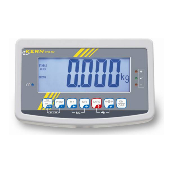
Page 5: Appliance Overview
2 Appliance overview KFB-TM: Synthetic finish 1. Status of rechargeable battery 2. Keyboard 3. Weight display 4. Tolerance margin, see chap. 7.7 5. Weighing unit 6. RS-232 7. Input connection load cell cable 8. Guide rail support base / stand 9. - Page 6 KFN-TM: Stainless steel finish 1. Status of rechargeable battery 2. Keyboard 3. Weight display 4. For tolerance mark see chap. 7.7 5. Weighing unit 6. Input connection load cell cable 7. Mains adapter connection KFB/KFN-TM-BA_IA-e-1624...
-
Page 7: Keyboard Overview
2.1 Keyboard overview Function • Turn on/off • Zeroing • Confirm entry Navigation button • Taring • At numeric input increase flashing digit Navigation key • Scroll forward in menu • Display sum total • Digit selection to the right Navigation key ... -
Page 8: Numerical Input Via The Navigation Buttons
2.1.1 Numerical input via the navigation buttons Press and current setting will be displayed. The first digit will be flashing and is ready for changing. If you do not wish to change the first digit, press and the second digit will start flashing. -
Page 9: Overview Of Display
2.2 Overview of display Display Significance Weighing range 1 Weighing range 2 Battery very low STABLE Stability display ZERO Zero indicator GROSS Gross weight Net weight AUTO Automatic add-up enabled Weighing unit Totalisation Indicators for weighing with tolerance range + / / - KFB/KFN-TM-BA_IA-e-1624... -
Page 10: Basic Information (General)
The display unit may only be operated in accordance with the described default settings. Other areas of use must be released by KERN in writing. 3.3 Warranty Warranty claims shall be voided in case •... -
Page 11: Monitoring Of Test Resources
KERN’s home page (www.kern-sohn.com with regard to the monitoring of display units’ test substances and the test weights required for this. In KERN’s accredited DKD calibration laboratory test weights and display units may be calibrated (return to the national standard) fast and at moderate cost. -
Page 12: Unpacking And Placing
6 Unpacking and placing 6.1 Installation Site, Location of Use The display units are designed in a way that reliable weighing results are achieved in common conditions of use. Precise and fast work is achieved by selecting the right place for your display unit and your weighing plate. -
Page 13: Transportation Lock (Illustration Example)
6.4 Transportation lock (illustration example) Please note: if the display unit is used together with platform with transportation lock, this transportation lock must be released prior to use: Transport Securing 6.5 Error message As soon as an error message appears in the balance display, the balance must not more be used, e.g. -
Page 14: Placing
Usage with wall mount (KFB-TM only) Use the wall mount to affix the display unit to the wall. Using with tripod (optional) An optional tripod (KERN BFS-07) is available if the display unit is to be mounted in a raised position. KFB/KFN-TM-BA_IA-e-1624... -
Page 15: Mains Connection
6.7 Mains connection Power is supplied via the external mains adapter. The stated voltage value must be the same as the local voltage. Only use original KERN mains adapters. Using other makes requires consent by KERN. 6.8 Storage battery operation (optional) Before the first use, the battery should be charged by connecting it to the mains power supply for at least 12 hours. -
Page 16: Adjustment
Prepare the required adjustment weight. The weight to be used depends on the capacity of the scale. Carry out adjustment as near as possible to the scale’s maximum weight. Info about test weights can be found on the Internet at: http://www.kern-sohn.com. • Observe stable environmental conditions. Stabilisation requires a certain warm-up time. - Page 17 „PO CHK“ will be displayed. 3. Press repeatedly until „P2 mode“ will be displayed. For the KFB-TM model operate the adjustment switch. 4. Press and select the set weighing scales type by = Single-range balance = Dual range balance ...
- Page 18 How to carry out an adjustment: Confirm menu setting „noLin“ by Ensure that there are no objects on the weighing plate. Wait for stability display, then press The currently set adjustment weight will be displayed. To change by using the navigation buttons (see chap.
-
Page 19: Non Verifiable Weighing Systems
6.9.2 Non verifiable weighing systems Call up menu: 1. Switch-on balance and during the selftest press 2. Press subsequently the first menu block „PO CHK“ will be displayed. 3. Press repeatedly until „P3 CAL“ will be displayed. 4. Confirm with ;... -
Page 20: Linearization
6.10 Linearization Linearity shows the greatest deviation of a weight display on the scale to the value of the respective test weight according to plus and minus over the entire weighing range. If linearity deviation is discovered during a testing instrument control, you can improve this by means of linearization. -
Page 21: Non-Verified Weighing Systems
After linearisation the balance will carry out a self-test. Remove adjusting weight during selftest, balance will return into weighing mode automatically. 6.10.2 Non-verified weighing systems Call-up menu item P3 CALCalLiner, see chap. 6.9.1 Confirm by , the password query „Pn“ will be displayed. ... -
Page 22: Verification
6.11 Verification General introduction: According to EU directive 90/384/EEC balances must be officially verified if they are used as follows (legally controlled area): a) For commercial transactions if the price of goods is determined by weighing. b) For the production of medicines in pharmacies as well as for analyses in the medical and pharmaceutical laboratory. -
Page 23: Kfb/Kfn-Tm-Ba_Ia-E
Notes on verified weighing systems KFB-TM: Access to conductor plate: • Remove seal • Open display unit • The application of the display unit as a weighing system able to be verified requires that the contacts of the circuit board are short-circuited with the help of a jumper [K1]. - Page 24 KFN-TM: Access to conductor plate: • Remove seal • Open display unit • The application of the display unit as a weighing system able to be verified requires that the contacts of the circuit board are short-circuited with the help of a jumper [K1].
-
Page 25: Operation
7 Operation 7.1 Start-up Press and the instrument will carry out a self-test. As soon as the weight display appears, the instrument will be ready to weigh. 7.2 Switching Off Press and the display will disappear. 7.3 Zeroing Resetting to zero corrects the influence of light soiling on the weighing plate. -
Page 26: Switch-Over Weighing Unit (Only Not Verifiable Weighing Systems)
7.5 Switch-over weighing unit (only not verifiable weighing systems) How to enable weighing units: Call-up menu item P5 Unt, see chap. 8.1 Press and the first weighing unit with the current setting will be displayed. To enable [on] / disable [off] the displayed weighing unit, press ... -
Page 27: Weighing With Tare
7.6 Weighing with tare Deposit weighing vessel. After successful standstill control press the button. Zero display and indicator appear. The weight of the container is now internally saved. Weigh the material, the net weight will be indicated. The weight of the weighing container will be displayed as a minus number after removing the weighing container. -
Page 28: Weighing With Tolerance Range
7.7 Weighing with tolerance range You can set an upper or lower limit when weighing with tolerance range and thus ensure that the weighed load remains exactly within the set limits. During tolerance tests such as dosing, portioning and sorting the unit will indicate exceeded or undershot limits by emitting an optical or acoustic signal. -
Page 29: Tolerance Check For Target Weight
7.7.1 Tolerance check for target weight Settings Press at the same time in weighing mode. Press until the display for entering the lower limit value appears. Press , the current setting will be displayed. To enter the lower limit, e. g. 1000 Kg, press the navigation keys (See chap. - Page 30 Press ; weighing system is in tolerance weighing mode. From here evaluation takes place whether the goods to be weighed are within the two tolerance limits. Weighing with tolerance range Tare when using a weighing container. Put on goods to be weighed, tolerance control is started. The signal lights indicate whether the load is within the two set limits.
-
Page 31: Tolerance Check For Target Quantity
7.7.2 Tolerance check for target quantity Settings Press at the same time in weighing mode. Press until the display for entering the lower limit value appears. Press , the current setting will be displayed. To enter the lower limit, e. g. 75 items, press the navigation buttons (see chap. - Page 32 Press ; weighing system is in tolerance weighing mode. From here evaluation takes place whether the goods to be weighed are within the two tolerance limits. Weighing with tolerance range Set item weight, see chap. 7.10. Tare when using a weighing container. ...
-
Page 33: Manual Totalizing
7.8 Manual totalizing With this function the individual weighing values are added into the summation memory by pressing and edited, when an optional printer is connected. • Menu setting: „P1 COM“ or „P2 COM“ „MODE“ „PR2““, see chap. 8 •... - Page 34 Press at the same time The data in the summation memory are deleted. Printout example KERN YKB-01N, verified weighing system: Menu setting Menu setting „P1 COM“ or „P2 COM“ „Lab 2“ / Prt 7“ „P1 COM“ or „P2 COM“ „Lab 0“ / Prt 0“...
-
Page 35: Automatic Adding-Up
7.9 Automatic adding-up With this function the individual weighing values are automatically added into the summation memory when the balance is unloaded without pressing and edited, when an optional printer is connected. • Menu settings: „P1 COM“ or „P2 COM „MODE“ „AUTO““, see chap. 8 Der Indikator wird angezeigt. -
Page 36: Parts Counting
7.10 Parts counting Before the balance can count parts, it must know the average part weight (i.e. reference). Proceed by putting on a certain number of the parts to be counted. The balance determines the total weight and divides it by the number of parts, the so- called reference quantity. -
Page 37: Animal Weighing
7.11 Animal weighing The animal weighing function is suitable for weighing restless loads. The weighing system will display a mean value derived from several weighing results. The animal weighing program can be enabled by either calling up menu block „P3 OTH“ or „P4 OTH“ „ANM“ „ON“ (See chap. 8) or faster via key combination. The indicator shows as long as the animal weighing function remains enabled. -
Page 38: Lock Keyboard
7.12 Lock keyboard To enable/disable the keyboard lock go to menu item „P3 OTH“ or „P4 OTH“ „LOCK“, see chap.8. Whilst the function is enabled the keyboard will self-lock after no key has been pressed for 10 minutes. „K-LCK“ will be displayed as soon as a key is pressed. To disable the lock, press hold plus (2 s) until „U LCK“... -
Page 39: Automatic Switch-Off Function „Auto Off
7.14 Automatic switch-off function „AUTO OFF“ The unit is automatically switched off within the preset time when the display unit or the weighing bridge are not operated. Keep pressed (3s) until „setbl“ appears. Press to call up -function AUTO OFF ... -
Page 40: Menu
8 Menu The application of the display unit as a verified weighing system requires that you short-circuit the two contacts [K1] of the circuit board, using a jumper. To that effect, a menu for verified weighing systems is available. For menu layout see chap. 8.2. There is no jumper for weighing systems that cannot be verified. -
Page 41: Overview Non Verifiable Weighing Systems (Contacts Of Circuit Board [K1] Not Short-Circuited)
8.1 Overview non verifiable weighing systems (contacts of circuit board [K1] not short-circuited) Menu block Menu item Available settings / explanation Main menu Submenu PO CHK nEt H Upper limit value „Tolerance check weighing“, input see chap. 7.7.1 Weighing with nEt LO Lower limit value „Tolerance check weighing“, input see tolerance range,... - Page 42 For automatic add-up see chap. 7.9. AUTO* This function is used to issue and add individual weighing values automatically to the summation memory on unloading of weighing scale. For remote control commands, see chap. 10.4 wirel Not documented BAUD Available Baudrate: 600, 1200, 2400, 4800, 9600* 7 bits, even parity 7 bits, odd parity 8n1*...
- Page 43 P5 Unt Switch-over off* weighing unit, see chap. 7.5 off* off* P6 xcl Not documented P7 rst to reset balance settings to factory default. P8 uwb Not documented Factory settings are marked by *. KFB/KFN-TM-BA_IA-e-1624...
-
Page 44: Overview Verified Weighing Systems (Contacts Of Circuit Board [K1] Short-Circuited By Means Of Jumper)
(contacts of circuit board [K1] short-circuited by means of jumper) In verified weighing systems the access to „P2 mode and „P4 tAr“ is locked. KERN KFB-TM: To disable the access lock, destroy the seal and actuate the adjustment switch. Position of the adjustment switch see chap. 6.11. - Page 45 For remote control commands, see chap. 10.4 Not documented wireless baud Available Baudrate: 600, 1200, 2400, 4800, 9600 7 bits, even parity 7 bits, odd parity 8 bits, no parity PtYPE tPUP Standard printer setting LP50 Not documented Lab x Details see following table 1 Prt x Lang...
- Page 46 dUAL 2 Multi-interval balance Weighing scales with one weighing range subdivided into partial weighing ranges, each providing a different scale interval. The scale interval depends on the applied load and is automatically changed during loading and unloading. COUNT Display internal resolution DECI Position of the decimal dot Readability [d] / verification value [e]...
-
Page 47: Service, Maintenance, Disposal
• Do not use aggressive detergents (solvents or similar). 9.2 Service, maintenance The appliance may only be opened by trained service technicians who are authorized by KERN. Before opening, disconnect from power supply. 9.3 Disposal Disposal of packaging and appliance must be carried out by operator according to valid national or regional law of the location where the appliance is used. - Page 48 • No data Err 10 Communication error • Range 0.9 ~ 1.0 Err 15 Gravitation error • Reduce load Err 17 Taring range exceeded Fai l h / • Repeat adjustment. Adjustment error Fai l l • Check communication parameters Err P Printer error Ba lo /...
-
Page 49: Data Output Rs 232C
• Use a suitable cable to connect the display unit to the interface of the printer. Faultless operation requires an adequate KERN interface cable. • Communication parameters (baud rate, bits and parity) of display unit and printer must match. -
Page 50: Output Log (Continuous Output)
Symbols: Stable value Instable value GS / GW Gross weight Net weight Tare weight Number weighing processes TOTAL Total of all individual weighings <lf> Space line <lf> Space line • Counting **************************** **************************** 10.3 Output log (continuous output) • Weighing HEADER1: ST=STABLE,... -
Page 51: Instant Help
11 Instant help In case of an error in the program process, briefly turn off the display unit and disconnect from power supply. The weighing process must then be restarted from the beginning. Help: Fault Possible cause The displayed weight does •... -
Page 52: Installing Display Unit / Weighing Bridge
12 Installing display unit / weighing bridge • Installation / configuration of a weighing system must be carried out by a well acquainted specialist with the workings of weighing balances. 12.1 Technical data Supply voltage: 5 V/150mA Max. signal voltage 0-10 mV Zeroing range 0-2 mV... -
Page 53: How To Connect The Platform
12.3 How to connect the platform Disconnect the display unit from the power supply. Solder the individual leads of the load cell cable onto the circuit board. See diagrams below. EXC+ SEN+ SIG+ SIG- LOAD CELL SEN- SHIELD EXC- Loadcell 6- conductor 4- conductor... -
Page 54: Configure Display Unit
Press subsequently, the first menu block „PO CHK“ will be displayed. Press repeatedly until „P2 mode“ will be displayed. Operate the adjustment switch (models KFB-TM). Press and use to select the weighing scales type. Single-range balance Dual range balance ... - Page 55 Example single range scales (d = 10 g, max. 30 kg) Confirm selected weighing scales type by pressing ; the first menu item „COUNT“ will be shown. 1. Display internal resolution Press , the internal resolution will be shown. ...
- Page 56 4. Capacity Press , the current setting will be displayed. Using the navigation buttons (see chap. 2.1.1) select the desired setting, the active digit is flashing. Confirm input by Press to select the next menu item. 5. Adjustment / linearization Adjustment or linearization is required after entering configuration data.
- Page 57 Example dual range scales (d = 2 / 5 g, max. 6 / 15 kg) Confirm selected weighing scales type by ; the first menu item „COUNT“ will be shown. 1. Display internal resolution Press , the internal resolution will be shown. ...
- Page 58 3. Readability Press , the display used to enter readability/verification value for first weighing range will appear. Press , the current setting will be displayed. Select desired setting with and acknowledge by Press to enter the next menu item for readability/verification value for second weighing range.
- Page 59 4. Capacity Press and the display for entering the capacity for the first weighing range will appear. Press and current setting will be displayed. Select desired setting with and acknowledge by Press to select the next menu item used to enter the capacity for the second weighing range.
-
Page 60: Non Verifiable Weighing Systems (Contacts Of Circuit Board [K1] Not Short-Circuited )
12.4.2 Non verifiable weighing systems (contacts of circuit board [K1] not short-circuited ) + For menu overview see chap. 8.1. Call up menu Switch-on balance and during the selftest press Press subsequently , the first menu block „PO CHK“ will be displayed. ... - Page 61 Parameter selection Display internal resolution Press , the internal resolution will be shown. Return to menu by to select another menu item. Position decimal point Press , the currently set position of the decimal dot is displayed.
- Page 62 Select desired setting with and acknowledge by Press , the display for entering capacity will appear (at dual range balance for the first range). Press , the current setting will be shown (such as max. = 2000kg). ...
- Page 63 Press , the display for entering the readability of the second weighing range will appear. Press , the current setting will be displayed. Select desired setting with and acknowledge by Press , the unit will return to the menu ...
-
Page 64: Declaration Of Conformity / Test Certificate
13 Declaration of Conformity / Test Certificate To view the current EC/EU Declaration of Conformity go to: www.kern-sohn.com/ce • The scope of delivery for verified weighing balances (= conformity-rated weighing balances) includes a Declaration of Conformity. KFB/KFN-TM-BA_IA-e-1624... - Page 65 TEST CERTIFICATE No. DK0199-R76-11.04 KFN-TM / KFB-TM Instrument type Test item device Non-automatic Weighing Indicator Issued by DELTA Danish Electronics, Light & Acoustics EU - Notified Body No. 0199 In accordance with Paragraph 8.1 of the European Standard on metrological aspects of non-automatic weighing instruments EN 45501:1992.
- Page 66 52 mm. The enclosure is made of stainless steel for the KFN-TM indicator or of ABS plastics for KFB-TM. The front of the enclosure has an on/off key plus 6 keys for operating the functions of the indicator.
- Page 67 Weighing unstable samples • Real time clock (optional) • Technical data Indicator Type KFN-TM / KFB-TM Accuracy class III or IIII Weighing range Single-interval, multi-interval or multi-range Maximum number of verification scale intervals (n) 6000 for single-interval 2×3000 for multi-interval and multi-range,...
- Page 68 Annex page 3 of 7 Annex to Test Certificate No. DK0199-R76-11.04 Interfaces Load cell interface Refer to section 3.1.1. Any load cell(s) can be used for instruments under this certificate provided the following conditions are met: There is a respective test certificate (EN 45501) or an OIML Certificate of Conformity (R60) •...
- Page 69 Annex page 4 of 7 Annex to Test Certificate No. DK0199-R76-11.04 Location of seals and inscriptions Seals shall bear the verification mark of a notified body or alternative mark of the manufacturer ac- cording to ANNEX II, section 2.3 of the Directive 2009/23/EC. The seals shall be placed so that the enclosure can not be opened.
- Page 70 Annex page 5 of 7 Annex to Test Certificate No. DK0199-R76-11.04 Documentation Contents of the technical documentation held by the notified body: Product specification Manuals and descriptions • Drawings • Etc. • Examination report OIML R76 report no. DANAK-1910568, DANAK-1910388 and NMi 709226. Test results Report no.
- Page 71 Annex page 6 of 7 Annex to Test Certificate No. DK0199-R76-11.04 Pictures Figure 1 Sealing of KFN-TM. Issued by DELTA...
- Page 72 Annex page 7 of 7 Annex to Test Certificate No. DK0199-R76-11.04 Figure 2 Sealing of KFB-TM. Issued by DELTA...
Need help?
Do you have a question about the KFB-TM and is the answer not in the manual?
Questions and answers