Table of Contents
Advertisement
Quick Links
Download this manual
See also:
Installation Manual
Advertisement
Table of Contents

Related Manuals for Allied Vision GUPPY PRO


Summary of Contents for Allied Vision GUPPY PRO
- Page 1 Guppy PRO Technical Manual V4.1.2 2017-Apr-07 Allied Vision Technologies GmbH Taschenweg 2a, 07646 Stadtroda / Germany...
-
Page 2: Legal Notice
These products are not designed for use in life support appliances, devices, or systems where malfunction of these products can reasonably be expected to result in personal injury. Allied Vision Technologies customers using or selling these products for use in such applications do so at their own risk and agree to fully indemnify Allied for any damages resulting from such improper use or sale. -
Page 3: Table Of Contents
IEEE1394b bandwidths........................28 Requirements for PC and IEEE1394b..................29 Example 1: IEEE1394b bandwidth of Guppy PRO cameras............. 29 Example 2: More than one Guppy PRO camera at full speed..........30 FireWire Plug & play capabilities....................30 FireWire hot-plug and screw-lock precautions................31 Operating system support...................... - Page 4 Guppy PRO F-201B, F-201C......................55 Guppy PRO F-503B, F-503C......................56 Camera dimensions .........................57 Guppy PRO standard housing (1 × IEEE1394b copper) ..............57 Tripod adapter ............................ 58 Cross section: C-Mount ........................59 Cross section: CS-Mount ........................60 Adjustment of C-Mount/CS-Mount....................61 Filter and lenses ..........................62...
- Page 5 2 × binning (Guppy PRO F-503 also 4 ×) ..................103 Vertical binning..........................104 Horizontal binning ........................106 2 × full binning (Guppy PRO F-503 also 4 × full binning) ............108 Sub-sampling (Guppy PRO F-503B, F-503C and monochrome CCD models)........110 What is sub-sampling? ........................ 110 Which Guppy PRO models have sub-sampling? .................
- Page 6 Controlling image capture ......................123 Global shutter (CCD cameras only) ....................123 Electronic rolling shutter (ERS) and global reset release shutter (GRR) (Guppy PRO F-503 only).. 124 Trigger modes ........................... 125 Trigger_Mode_0 (edge mode) and Trigger_Mode_1 (level mode) ........... 126 Guppy PRO F-503, Trigger_Mode_0, electronic rolling shutter..........126 Guppy PRO F-503, Trigger_Mode_0, global reset release shutter ........
- Page 7 Guppy PRO F-031: AOI frame rates..................... 170 Guppy PRO F-032: AOI frame rates..................... 171 Guppy PRO F-033: AOI frame rates..................... 172 Guppy PRO F-046: AOI frame rates..................... 173 Guppy PRO F-125: AOI frame rates..................... 174 Guppy PRO F-146: AOI frame rates..................... 175 Guppy PRO F-201: AOI frame rates.....................
- Page 8 Error codes ..........................240 Reset of error codes....................... 240 Stored settings ........................240 Pulse-width modulation (PWM)....................242 Global reset release shutter (Guppy PRO F-503 only)..............242 GPDATA_BUFFER......................... 242 Little endian vs. big endian byte order .................. 243 Firmware update ..........................244 Extended version number (FPGA/µC) ....................
-
Page 9: Contacting Allied Vision
Contacting Allied Vision Connect with Allied Vision colleagues by function: www.alliedvision.com/en/contact Find an Allied Vision office or distributor: www.alliedvision.com/en/about-us/where-we-are.html Email: info@alliedvision.com (for commercial and general inquiries) support@alliedvision.com (for technical assistance with Allied Vision products) Sales offices Europe, Middle East, and Africa: +49 36428-677-230... -
Page 10: Introduction
Introduction This Guppy PRO Technical Manual describes in depth the technical specifications, dimensions, all camera features (IIDC standard and Allied Vision smart features) and their registers, trigger features, all video and color formats, bandwidth and frame rate calculation. For information on hardware installation, safety warnings, pin assignments on I/O connectors and IEEE1394b connectors read the 1394 Installation Manual. - Page 11 47 and Video Format_7 default modes Guppy PRO F-503B, F-503C on page 161 • Added Guppy PRO F-503 frame rate and bandwidth: see Table 4: Bandwidth of Guppy PRO models on page 29 • Changed maximum resolution of Guppy PRO F-503 from 2592 ×...
- Page 12 • End of exposure to first packet on the bus Some minor corrections: • Guppy PRO cameras have 1 input / 3 outputs (not 2/4) in Pulse-width modulation on page 78 • Corrected frame rates of Guppy PRO F-031 (121 fps),...
- Page 13 – Figure 9: Guppy PRO F-033B, F-033C (Sony ICX414) absolute QE on page 51 – New: Table 17: Guppy PRO F-033, F-046, F-146 focal length vs. field of view on page 64 – Video fixed formats Guppy PRO F-033B, F-033C –...
- Page 14 91: Frame rates as function of AOI height [width=656] on page • 188 fps instead of 199 fps (F7M2, Mono16), see Table 72: Video Format_7 default modes Guppy PRO F-031B, F-031C page 147 Guppy PRO F-032 • F7M0 (Raw8/Raw12/Raw16/YUV411/YUV422/Mono8/ Mono12/Mono16): 82 fps instead of 79 fps, see...
- Page 15 Guppy PRO F- 201: AOI frame rates on page 176 • For Guppy PRO F-201B/C: Added fixed frame rate 15 fps, see Guppy PRO F-201B, F-201C on page 45 • Changed with zero overshot to to with minimum overshot: see...
- Page 16 Contacting Allied Vision on page 9 • Corrected information for binning in Definition on page 103 • Corrected block diagram for Guppy PRO color cameras in Block diagrams of Guppy PRO models on page 85 • Updated sensor curves in...
-
Page 17: Manual Overview
(1394 Installation Manual), available Allied Vision software (including documentation) and where to get it. • Guppy PRO cameras provides a short introduction to the Guppy PRO cameras with their FireWire technology. Links are provided to data sheets and brochures on Allied Vision website. •... -
Page 18: Conventions Used In This Manual
FPGA/micro controller. • Appendix lists the sensor position accuracy of Allied Vision cameras. • Index gives you quick access to all relevant data in this manual. Conventions used in this manual To give this manual an easily understood layout and to emphasize important information, the following typographical styles and symbols are used. -
Page 19: More Information
You find the 1394 Installation Manual here: https://www.alliedvision.com/en/support/technical- documentation All software packages (including documentation and release notes) provided by Allied Vision can be downloaded at: https://www.alliedvision.com/en/support/software- downloads Before operation We place the highest demands for quality on our cameras. - Page 20 Caution Before operating any Allied Vision camera read safety instructions and ESD warnings in 1394 Installation Manual. Note To demonstrate the properties of the camera, all examples in this manual are based on the FirePackage OHCI API software ...
-
Page 21: Guppy Pro Cameras
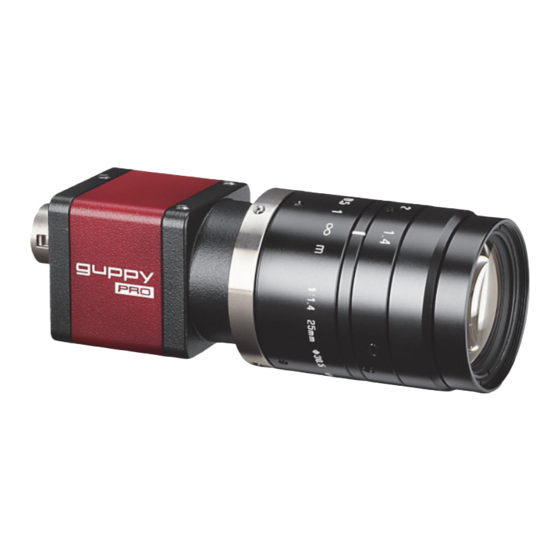
Guppy PRO cameras Guppy PRO With Guppy PRO cameras, entry into the world of digital image processing is simpler and more cost-effective than ever before. Guppy PRO cameras are the smallest IEEE1394b cameras worldwide. IEEE1394b With the Guppy PRO, Allied Vision presents a wide range of cameras with IEEE1394b interfaces. -
Page 22: Conformity
Conformity Allied Vision Technologies declares under its sole responsibility that all standard cameras of the Guppy PRO family to which this declaration relates are in conformity with the following standard(s) or other normative document(s): • CE, following the provisions of 2004/108/EG directive •... -
Page 23: Firewire
IEEE Std. 1394a-2000 amendment • IEEE Std. 1394b-2002 amendment FireWire is used to connect digital cameras, especially in industrial systems for machine vision. Note All naming in this document relates to FirePackage, not to GenICam. Guppy PRO Technical Manual V4.1.2... -
Page 24: Why Use Firewire
As illustrated in the diagram below, these two modes can co-exist by using priority time slots for video data transfer and the remaining time slots for control data transfer. Figure 2: IEEE1394a data transmission Guppy PRO Technical Manual V4.1.2... -
Page 25: Firewire Connection Capabilities
current of 18 mJoule in 3 ms. Higher inrush current may damage the PHY chip of the camera and/or the PHY chip in your PC. Guppy PRO Technical Manual V4.1.2... -
Page 26: Capabilities Of Ieee1394A (Firewire 400)
IIDC V1.3 released a set of camera control standards via IEEE1394a, which established a common communications protocol on which most current FireWire cameras are based. In addition to common standards shared across manufacturers, Allied Vision offers Format_7 mode that provides special features (smart features), such as: •... -
Page 27: Compatibility Between Ieee1394A And Ieee1394B
It is possible to run a IEEE1394a and a IEEE1394b camera on the IEEE1394b bus. You can e.g. run a Guppy PRO F-032B and a Marlin F-033B on the same bus: • Guppy PRO F-032B @ S800 and 60 fps (2560 bytes per cycle, 32% of the cycle slot) •... -
Page 28: Image Transfer Via Ieee1394A And Ieee1394B
1 MByte = 1024 KB IEEE1394b bandwidths According to the IEEE1394b specification on isochronous transfer, the largest recommended data payload size is 8192 bytes per 125 µs cycle at a bandwidth of 800 Mbit/s. Guppy PRO Technical Manual V4.1.2... -
Page 29: Requirements For Pc And Ieee1394B
Higher inrush current may damage the physical interface (PHY) chip of the camera and/or the PHY chip in your PC. For a single Guppy PRO camera inrush current may not be a problem. But daisy chaining multiple cameras or supplying bus power via (optional) Hirose power out to circuitry with unknown inrush currents needs careful design considerations. -
Page 30: Example 2: More Than One Guppy Pro Camera At Full Speed
Due to the fact that one Guppy PRO camera can, depending on its settings, saturate a 32-bit PCI bus, you are advised to use either a PCI Express card and/ or multiple 64-bit PCI bus cards, if you want to use 2 or more Guppy PRO cameras simultaneously (see the following table). -
Page 31: Firewire Hot-Plug And Screw-Lock Precautions
• Higher inrush current may damage the physical interface chip of the camera and/or the PHY chip in your PC. For a single Guppy PRO camera inrush current may not be a problem. But daisy chaining multiple cameras or supplying bus power via (optional) Hirose power out to circuitry with unknown inrush currents needs careful design considerations. -
Page 32: Operating System Support
MS1394 driver will continue to work.) Microsoft Windows 7 Full support Full support Microsoft Windows 8 Full support Full support Table 6: FireWire and operating systems For more information see Allied Vision Software: https://www.alliedvision.com Guppy PRO Technical Manual V4.1.2... -
Page 33: Specifications
Auto gain control (AGC), auto exposure control (AEC), autofunction AOI, look-up table (LUT), 1 storable user set Guppy PRO F-031B: Binning, sub-sampling Guppy PRO F-031C: Auto white balance (AWB), color correction, hue, saturation I/Os 1 configurable input (optocoupled), 3 configurable outputs (optocoupled) - Page 34 Standard accessories Guppy PRO F-031B: Protection glass Guppy PRO F-031C: IR cut filter Optional accessories Guppy PRO F-031B: IR cut filter, IR pass filter Guppy PRO F-031C: Protection glass On request Host adapter card, power out 6 W (Hirose) Software packages https://www.alliedvision.com/en/support/software-downloads...
-
Page 35: Guppy Pro F-032B, F-032C
Auto gain control (AGC), auto exposure control (AEC), autofunction AOI, look-up table (LUT), 1 storable user set Guppy PRO F-032B: Binning, sub-sampling Guppy PRO F-032C: Auto white balance (AWB), color correction, hue, saturation I/Os 1 configurable input (optocoupled), 3 configurable outputs (optocoupled) - Page 36 Feature Specification Optional accessories Guppy PRO F-032B: IR cut filter, IR pass filter Guppy PRO F-032C: Protection glass On request Host adapter card, power out 6 W (Hirose) Software packages https://www.alliedvision.com/en/support/software-downloads Table 8: Guppy PRO F-032B, F-032C model specifications (continued)
-
Page 37: Guppy Pro F-033B, F-033C
Auto gain control (AGC), auto exposure control (AEC), autofunction AOI, look-up table (LUT), 1 storable user set Guppy PRO F-033B: Binning, sub-sampling Guppy PRO F-033C: Auto white balance (AWB), color correction, hue, saturation I/Os 1 configurable input (optocoupled), 3 configurable outputs (optocoupled) - Page 38 Feature Specification Optional accessories Guppy PRO F-033B: IR cut filter, IR pass filter Guppy PRO F-033C: Protection glass On request Host adapter card, power out 6 W (Hirose) Software packages https://www.alliedvision.com/en/support/software-downloads Table 9: Guppy PRO F-033B, F-033C model specifications (continued)
-
Page 39: Guppy Pro F-046B, F-046C
Auto gain control (AGC), auto exposure control (AEC), autofunction AOI, look-up table (LUT), 1 storable user set Guppy PRO F-046B: Binning, sub-sampling Guppy PRO F-046C: Auto white balance (AWB), color correction, hue, saturation I/Os 1 configurable input (optocoupled), 3 configurable outputs (optocoupled) - Page 40 Feature Specification Optional accessories Guppy PRO F-046B: IR cut filter, IR pass filter Guppy PRO F-046C: Protection glass On request Host adapter card, power out 6 W (Hirose) Software packages https://www.alliedvision.com/en/support/software-downloads Table 10: Guppy PRO F-046B, F-046C model specifications (continued)
-
Page 41: Guppy Pro F-125B, F-125C
Auto gain control (AGC), auto exposure control (AEC), autofunction AOI, look-up table (LUT), 1 storable user set Guppy PRO F-125B: Binning, sub-sampling Guppy PRO F-125C: Auto white balance (AWB), color correction, hue, saturation I/Os 1 configurable input (optocoupled), 3 configurable outputs (optocoupled) - Page 42 Feature Specification Optional accessories Guppy PRO F-125B: IR cut filter, IR pass filter Guppy PRO F-125C: Protection glass On request Host adapter card, power out 6 W (Hirose) Software packages https://www.alliedvision.com/en/support/software-downloads Table 11: Guppy PRO F-125B, F-125C model specifications (continued)
-
Page 43: Guppy Pro F-146B, F-146C
Color modes Guppy PRO F-146C: Raw8, Raw12, Raw16, Mono8, YUV411, YUV422, RGB8 Frame rates 1.875 fps; 3.75 fps; 7.5 fps; 15 fps; 30 fps (Guppy PRO F-146C) Up to 17 fps in Format_7 Gain control Manual: 0 to 24.4 dB (0.0359 dB/step); auto gain (select. AOI) Shutter speed 41 µs to 67,108,864 µs (~ 67 s);... - Page 44 Feature Specification Accessories Guppy PRO F-146B: IR cut filter, IR pass filter Guppy PRO F-146C: Protection glass On request Host adapter card, power out 6 W (Hirose) Software packages https://www.alliedvision.com/en/support/software-downloads Table 12: Guppy PRO F-146B, F-146C model specifications (continued) Guppy PRO Technical Manual V4.1.2...
-
Page 45: Guppy Pro F-201B, F-201C
Auto gain control (AGC), auto exposure control (AEC), autofunction AOI, look-up table (LUT), 1 storable user set Guppy PRO F-201B: Binning, sub-sampling Guppy PRO F-201C: Auto white balance (AWB), color correction, hue, saturation I/Os 1 configurable input (optocoupled), 3 configurable outputs (optocoupled) - Page 46 Feature Specification Optional accessories Guppy PRO F-201B: IR cut filter, IR pass filter Guppy PRO F-201C: Protection glass On request Host adapter card, power out 6 W (Hirose) Software packages https://www.alliedvision.com/en/support/software-downloads Table 13: Guppy PRO F-201B, F-201C model specifications (continued)
-
Page 47: Guppy Pro F-503B, F-503C
22: on page 12-bit Color modes Guppy PRO F-503C: Raw8, Raw12, Raw16, Mono8/12/16 (all F7 modes), YUV411 (all F7 modes), YUV422 (all F7 modes) Frame rates 1.875 fps; 3.75 fps; 7.5 fps; 15 fps; 30 fps; 60 fps; 120 fps; Format_7: variable frame rates up to 13 fps at full resolution;... -
Page 48: Absolute Quantum Efficiency (Qe)
Standard accessories Guppy PRO F-503B: Protection glass Guppy PRO F-503C: IR cut filter Optional accessories Guppy PRO F-503B: IR cut filter, IR pass filter Guppy PRO F-503C: Protection glass On request Host adapter card, power out 6 W (Hirose) Software packages https://www.alliedvision.com/en/support/software-downloads... -
Page 49: Guppy Pro F-031B, F-031C
The uncertainty in measurement of the QE is +/ 10.25%. The values are typical and are subject to minor variations. 1000 Wavelength [nm] Figure 5: Guppy PRO F-031B, F-031C (Sony ICX618) absolute QE Red Response Green Response Blue Response Monochrome QE 0.4000... -
Page 50: Guppy Pro F-032B, F-032C
The uncertainty in measurement of the QE is +/ 10.25%. The values are typical and are subject to minor variations. 1000 Wavelength [nm] Figure 7: Guppy PRO F-032B, F-032C (Sony ICX424) absolute QE Red Response Green Response Blue Response Monochrome Response 0.2000... -
Page 51: Guppy Pro F-033B, F-033C
The uncertainty in measurement of the QE is +/ 10.25%. The values are typical and are subject to minor variations. 1000 Wavelength [nm] Figure 9: Guppy PRO F-033B, F-033C (Sony ICX414) absolute QE Red Response Green Response Blue Response Monochrome Response 0.2000... -
Page 52: Guppy Pro F-046B, F-046C
The uncertainty in measurement of the QE is +/ 10.25%. The values are typical and are subject to minor variations. 1000 Wavelength [nm] Figure 11: Guppy PRO F-046B, F-046C (Sony ICX415) absolute QE Red Response Greeen Response Blue Response Monochrome Response 0.2000... -
Page 53: Guppy Pro F-125B, F-125C
The uncertainty in measurement of the QE is +/ 10.25%. The values are typical and are subject to minor variations. 1000 Wavelength [nm] Figure 13: Guppy PRO F-125B, F-125C (Sony ICX445) absolute QE Red Response Green Response Blue Response Monochrome Response 0.3000... -
Page 54: Guppy Pro F-146B, F-146C
The uncertainty in measurement of the QE is +/ 10.25%. The values are typical and are subject to minor variations. 1000 Wavelength [nm] Figure 15: Guppy PRO F-146B, F-146C (Sony ICX267) absolute QE Red Response Green Response Blue Response Monochrome Response 0.2000... -
Page 55: Guppy Pro F-201B, F-201C
The uncertainty in measurement of the QE is +/ 10.25%. The values are typical and are subject to minor variations. 1000 Wavelength [nm] Figure 17: Guppy PRO F-201B, F-201C (Sony ICX274) absolute QE Red Response Green Response Blue Response Monochrome Response 0.3000... -
Page 56: Guppy Pro F-503B, F-503C
The uncertainty in measurement of the QE is +/ 10.25%. The values are typical and are subject to minor variations. 1090 1190 Wavelength [nm] Figure 19: Guppy PRO F-503B, F-503C (ON Semiconductor MT9P031) absolute QE Guppy PRO Technical Manual V4.1.2... -
Page 57: Camera Dimensions
Camera dimensions Note For information on sensor position accuracy: Sensor position accuracy of Guppy PRO cameras on page 245. Guppy PRO standard housing (1 × IEEE1394b copper) M3x3 (3x) 23.8 12.3 10.3 C-Mount M3x3 (3x) 38.5 44.8 Figure 20: Camera dimensions (1 × IEEE1394b copper) -
Page 58: Tripod Adapter
Tripod adapter This three hole tripod adapter (Allied Vision order code 1216) to • to can be used for Guppy PRO only. • to is only designed for standard housings. UNC 1/4-20, 6 mm thread depth 3.2 (3x) Body size: 29 mm × 30 mm × 10 mm (L × W × H) Figure 21: Tripod dimensions Guppy PRO Technical Manual V4.1.2... -
Page 59: Cross Section: C-Mount
Cross section: C-Mount • All monochrome Guppy PRO cameras are equipped with the same model of protection glass. • All color Guppy PRO cameras are equipped with the same model of IR cut filter. Maximum filter / protection glass protrusion: 10.7... -
Page 60: Cross Section: Cs-Mount
Cross section: CS-Mount All Guppy PRO cameras can be delivered with CS-Mount. maximum protrusion: filter / protection glass CS-Mount Figure 23: Guppy PRO CS-Mount dimension Note Pay attention to the maximum sensor size of the applied CS- Mount lens. ... -
Page 61: Adjustment Of C-Mount/Cs-Mount
For all customers who know the C-Mount adjustment procedure from Pike cameras: The front flange of Guppy PRO cameras is a fixed part of the camera (and cannot be screwed). As mentioned above: adjustment of C-Mount with Guppy PRO cameras can only be made by Allied Vision. -
Page 62: Filter And Lenses
Figure 24: Approximate spectral transmission of IR cut filter (may vary slightly by filter lot) (type Hoya C5000) Camera lenses Allied Vision offers different lenses from a variety of manufacturers. The following table lists selected image formats in width × height depending on camera type, distance and the focal length of the lens. -
Page 63: Guppy Pro F-031
226 mm × 170 mm 25 mm 70 mm × 53 mm 143 mm × 108 mm Table 15: Guppy PRO F-031 focal length vs. field of view Guppy PRO F-032 Field of view Focal length Distance = 500 mm Distance = 1000 mm 2.8 mm... -
Page 64: Guppy Pro F-033, F-046, F-146
176 mm × 132 mm 50 mm 58 mm × 43 mm 122 mm × 91 mm Table 17: Guppy PRO F-033, F-046, F-146 focal length vs. field of view Guppy PRO F-201 Field of view Focal length Distance = 500 mm Distance = 1000 mm 4.8 mm... -
Page 65: Guppy Pro F-503
50 mm 0.04 m × 0.05 m 0.08 m × 0.11 m Table 19: Guppy PRO F-503 focal length vs. field of view Note Lenses with focal lengths < 8 mm may show shading in the edges of the image and due to micro lenses on the sensor's ... -
Page 66: Camera Interfaces
IEEE1394 bus and thus makes it possible to control the camera and output frames. For more information on cables and on ordering cables online (by clicking the article and sending an inquiry) go to: https://www.alliedvision.com/en/contact Guppy PRO Technical Manual V4.1.2... -
Page 67: Camera I/O Connector Pin Assignment
Input Ground (In GND) White Black Camera Out Common VCC for External Power Orange Power outputs for digital outputs max. 36 VDC (OutVCC) Table 20: Camera I/O connector pin assignment and Guppy PRO trigger cable color coding Guppy PRO Technical Manual V4.1.2... - Page 68 Open emitter Camera Output 2 White/Brown (GPOut2) default: Off Table 20: Camera I/O connector pin assignment and Guppy PRO trigger cable color coding (continued) For cable color and pin out information, see the Allied Vision Note I/O cable data sheet: ...
-
Page 69: Status Leds
GREEN permanent on Power on GREEN Bus reset not available Asynchronous traffic +GREEN pulsing Isochronous traffic +GREEN pulsing Waiting for external trigger GREEN External trigger event GREEN +RED pulsing Table 21: LEDs showing normal conditions Guppy PRO Technical Manual V4.1.2... -
Page 70: Error Conditions
Table 22: Error codes Video mode error: These are error modes according IIDC specification: Vmode_Error_Status register (wrong settings of video mode, format, frame rate and ISO settings). Format 7 error: see Format 7 register description of IIDC specification. Guppy PRO Technical Manual V4.1.2... -
Page 71: Control And Video Data Signals
Inputs Note For a general description of the inputs and warnings see the 1394 Installation Manual, Chapter Guppy PRO input description. The optocoupler inverts all input signals. Inversion of the signal is controlled via the IO_INP_CTRL1..2 register (see... -
Page 72: Input/Output Pin Control
Default 0x00 0x01 Reserved 0x02 Trigger input Input 1 0x03..0x1F Reserved Table 24: Input routing Note If you set more than 1 input to function as a trigger input, all trigger inputs are ANDed. Guppy PRO Technical Manual V4.1.2... -
Page 73: Trigger Delay
Trigger delay Guppy PRO cameras feature various ways to delay image capture based on external trigger. With IIDC V1.31 there is a standard CSR at Register F0F00534/834h to control a delay up to FFFh × time base value. The following table explains the inquiry register and the meaning of the various bits. - Page 74 The advanced register allows the start of the integration to be delayed by max. µs, which is max. 2.1 s after a trigger edge was detected. Note • Switching trigger delay to ON also switches external Trigger_Mode_0 to ON. • This feature works with external Trigger_Mode_0 only. Guppy PRO Technical Manual V4.1.2...
-
Page 75: Outputs
Outputs Note For a general description of the outputs and warnings see the 1394 Installation Manual, Chapter Guppy PRO output description. Output features are configured by software. Any signal can be placed on any output. The main features of output signals are described below. -
Page 76: Io_Outp_Ctrl 1-3
[11 to 15] Mode table 30:. [16 to 30] Reserved PinState [31] RD: Current state of pin WR: New state of pin 0xF1000324 IO_OUTP_CTRL2 Same as IO_OUTP_CTRL1 0xF1000328 IO_OUTP_CTRL3 Same as IO_OUTP_CTRL1 Table 29: Advanced register: Output control Guppy PRO Technical Manual V4.1.2... -
Page 77: Output Modes
Output 2 0x08 Follow corresponding input (Inp1 Out1, Inp2 Out2) 0x09 PWM (=pulse-width modulation) Guppy PRO housing models 0x0A WaitingForTrigger Only in Trigger Edge Mode. All other Mode = 0 WaitingForTrigger is useful to know if a new trigger will be accepted. -
Page 78: Pulse-Width Modulation
[4 to 19] Minimum PWM period in µs (read only) [20 to 27] Reserved [28 to 31] Reserved 0xF1000804 PulseWidth [0 to 15] PWM pulse width in µs Period [16 to 31] PWM period in µs Table 31: PWM configuration registers Guppy PRO Technical Manual V4.1.2... -
Page 79: Pwm: Minimum And Maximum Periods And Frequencies
----------------------- - -------- - 333.33 kHz frequency max period min 3 μs --------------------------- 15.26 Hz frequency min 6 – 10 ------------------------------- - period max μs frequency min Formula 1: Minimum and maximum period and frequency Guppy PRO Technical Manual V4.1.2... -
Page 80: Pwm: Examples In Practice
1 in the sync bit (sy) of the packet header. sync bit 0 to 7 8 to 15 16 to 23 24 to 31 data_length channel tCode header_CRC Video data payload data_CRC Table 32: Isochronous data block packet format. Source: IIDC V1.31 Guppy PRO Technical Manual V4.1.2... -
Page 81: Description Of Video Data Formats
In 16-bit mode the data output is MSB aligned. Description of video data formats The following tables provide a description of the video data format for the different modes. (Source: IIDC V1.31; packed 12-bit mode: Allied Vision) <YUV8 (4:2:2) format> Each component has 8-bit data. - Page 82 Y component has 8-bit data. <Y (Mono8/Raw8) format> (K+0) (K+1) (K+2) (K+3) (K+4) (K+5) (K+6) (K+7) (K+Pn-8) (K+Pn-7) (K+Pn-6) (K+Pn-5) (K+Pn-4) (K+Pn-3) (K+Pn-2) (K+Pn-1) Table 36: Y (Mono8) format: Source: IIDC V1.31 / Y (Raw8) format: Allied Vision Guppy PRO Technical Manual V4.1.2...
- Page 83 (K+7) (K+7) [3..0] (K+6) Table 38: Packed 12-Bit Mode (mono and raw) Y12 format (Allied Vision) <Y(Mono8/Raw8), RGB8> Each component (Y, R, G, B) has 8-bit data. The data type is Unsigned Char. Y, R, G, B Signal level (decimal)
- Page 84 Y component has 12-bit data. The data type is unsigned. Signal level (decimal) Data (hexadecimal) Highest 4095 0x0FFF 4094 0x0FFE 0x0001 Lowest 0x0000 Table 42: Data structure of Packed 12-Bit Mode (mono and raw) (Allied Vision) Guppy PRO Technical Manual V4.1.2...
-
Page 85: Description Of The Data Path
(only CCD) 12 10 (only CCD) Some Guppy PRO models deliver 12-bit only. Figure 32: Block diagram monochrome camera Setting LUT = OFF effectively makes full use of the 14-bit by bypassing the LUT circuitry; setting LUT = ON means that the most significant 12-bit of the 14-bit are used and further down converted to 10-bit. -
Page 86: Color Models
(not continuously) • auto white balance (AWB): continuously optimizes the color characteristics of the image Guppy PRO color models have both one-push white balance and auto white balance. Guppy PRO Technical Manual V4.1.2... - Page 87 [20 to 31] V/R value This field is ignored when writing the value in Auto or OFF mode. If readout capability is not available, reading this field has no meaning. Table 43: White balance register Guppy PRO Technical Manual V4.1.2...
-
Page 88: One-Push White Balance
Range in dB 10 dB Guppy PRO 0 to 568 color models Table 44: U/V slider range for Guppy PRO models The increment length is ~0.0353 dB/step. One-push white balance Note Configuration To configure this feature in control and status register (CSR): ... -
Page 89: Auto White Balance (Awb)
Finally, the calculated correction values can be read from the WHITE_BALANCE register 80Ch. Auto white balance (AWB) The auto white balance feature continuously optimizes the color characteristics of the image. For the white balance algorithm the whole image or a subset of it is used. Guppy PRO Technical Manual V4.1.2... - Page 90 Figure 36: AUTOFNC_AOI positioning The algorithm is based on the assumption that the R-G-B component sums of the samples are equal, i.e., it assumes that the mean of the sampled grid pixels is to be monochrome. Guppy PRO Technical Manual V4.1.2...
-
Page 91: Auto Shutter
Auto shutter In combination with auto white balance, Guppy PRO models are equipped with auto shutter feature. When enabled, the auto shutter adjusts the shutter within the default shutter limits or within those set in advanced register F1000360h in order to reach the reference brightness set in auto exposure register. -
Page 92: Auto Gain
To configure this feature in an advanced register: See table 134: on page 228. Auto gain All Guppy PRO models are equipped with auto gain feature. Note Configuration To configure this feature in an advanced register, see table 135: ... - Page 93 Value [20 to 31] Read/Write Value This field is ignored when writing the value in Auto or OFF mode. If readout capability is not available, reading this field has no meaning. Table 46: CSR: Gain Guppy PRO Technical Manual V4.1.2...
- Page 94 Auto or OFF mode. If readout capability is not available, reading this field has no meaning. Table 47: CSR: Auto Exposure Note Configuration To configure this feature in an advanced register, see table 135: on page 230. Guppy PRO Technical Manual V4.1.2...
-
Page 95: Manual Gain
Target gray level) Manual gain Guppy PRO models are equipped with a gain setting, allowing the gain to be manually adjusted on the fly by means of a simple command register write. The following ranges can be used when manually setting the gain for the... -
Page 96: Mirror Function (Guppy Pro F-503B, F-503C)
Table 49: CSR: Brightness Mirror function (Guppy PRO F-503B, F-503C) Guppy PRO F-503 models are equipped with a mirror function, which is built directly into the sensor. The mirror is centered to the current FOV center and can be combined with all image manipulation functions, like binning. -
Page 97: Look-Up Table (Lut) And Gamma Function
RAW format has implications on the Bayer-ordering of the colors. Mirror OFF: G-R-B-G (Guppy PRO F-503C) Horizontal mirror ON: R-G-G-B (Guppy PRO F- 503C Figure 37: Mirror and Bayer order Note During switchover one image may be temporarily corrupted. -
Page 98: Loading An Lut Into The Camera
This gamma LUT is used with all Guppy PRO models. Gamma is known as compensation for the nonlinear brightness response of many displays e.g. CRT monitors. The look-up table converts the incoming 12 bit from the digitizer to outgoing 10 bit. - Page 99 (0) Figure 39: Loading an LUT Note Configuration • To configure this feature in an advanced register, see table 131: on page 224. • For information on GPDATA_BUFFER, see GPDATA_BUFFER on page 242. Guppy PRO Technical Manual V4.1.2...
-
Page 100: Defect Pixel Correction (Guppy Pro F-503B, F-503C)
Defect pixel correction (Guppy PRO F-503B, F-503C) The mechanisms of defect pixel correction are explained in the following drawings. All examples are done in Format_7 Mode_0 (full resolution). The first two examples are explained for monochrome models, the third and fourth example are explained for color models. -
Page 101: Building Defect Pixel Data
Mono8 color encoding, when using fixed modes. Set AOI to max. Set values for shutter, gain to max. Choose threshold Set BuildDPData to 1 Set ON_OFF to 1 Optional: Set MemSave to 1 Figure 41: Defect pixel correction: build and store Guppy PRO Technical Manual V4.1.2... -
Page 102: Grab An Image With Defect Pixel Data
Reset values (resolution, shutter, gain, brightness) Take the camera, remove lens cap and thread the lens onto the camera. Reset values for image resolution, shutter, gain and brightness (offset) to their previous values. Grab a single image (one-shot). Guppy PRO Technical Manual V4.1.2... -
Page 103: Activate/Deactivate Defect Pixel Correction
This is the current defect pixel count from the camera. Receive defect pixel data from the host Set EnaMemWR flag to 1. Binning (monochrome CCD models and Guppy PRO F-503B, F- 503C) 2 × binning (Guppy PRO F-503 also 4 ×) Definition Binning is the process of combining neighboring pixels while being read out from the sensor. -
Page 104: Vertical Binning
In the CCD sensors, this is done directly in the horizontal shift register of the monochrome sensor. With the CMOS sensor of Guppy PRO F-503B and F-503C, monochrome and color binning is possible. The monochrome CMOS sensor of Guppy PRO F-503B uses the same binning patterns as the color version. - Page 105 When the signals are averaged, the image will not be brighter than without binning. When the signals are added, the image will be brighter than without binning. Table 50: Definition of 2 × and 4 × vertical binning Figure 42: 2 × vertical binning (CCD models) Guppy PRO Technical Manual V4.1.2...
-
Page 106: Horizontal Binning
FPGA of the camera without accumulating the black level. CMOS models: horizontal binning is done in the CMOS sensor. With the CMOS sensor of Guppy PRO F-503C, color binning is possible. The monochrome CMOS sensor of Guppy PRO F-503B uses the same binning patterns as the color version. - Page 107 Low-noise binning For Guppy PRO F-503, low-noise binning (averaged pixel signals) is available. To activate this mode see Low-noise binning mode (2 × and 4 × binning) (Guppy PRO F-503 only) on page 237. Binning mode Monochrome CCD models Guppy PRO F-503B, F-503C 2 ×...
-
Page 108: Full Binning (Guppy Pro F-503 Also 4 × Full Binning)
If horizontal binning is activated the image may appear to be overexposed and must be corrected, if necessary. 2 × full binning (Guppy PRO F-503 also 4 × full binning) If horizontal and vertical binning are combined, every 4 (16) pixels are consolidated into a single pixel. - Page 109 When the signal is averaged, the image will not be brighter than without binning. When the signal is added, the image will be brighter than without binning. Table 52: Definition of 2 × and 4 × full binning Figure 46: Full binning (CCD models) Guppy PRO Technical Manual V4.1.2...
-
Page 110: Sub-Sampling (Guppy Pro F-503B, F-503C And Monochrome Ccd Models)
Definition Sub-sampling is the process of skipping neighboring pixels (with the same color) while being read out from the CCD chip. Which Guppy PRO models have sub-sampling? • CMOS Guppy PRO models (Guppy PRO F-503B, F-503C) have sub- sampling. • CCD Guppy PRO models: only monochrome models have sub-sampling... - Page 111 Format_7 Mode_4 By default and without further remapping use Format_7 Mode_4 for • Guppy PRO F-503B: 2 out of 4 horizontal sub-sampling • Guppy PRO F-503C: 2 out of 4 horizontal sub-sampling The different sub-sampling patterns are shown below. 2 out of 4...
- Page 112 The image appears vertically compressed in this mode and no longer exhibits a true aspect ratio. Format_7 Mode_6 By default and without further remapping use Format_7 Mode_6 for 2 out of 4 H + V sub-sampling Guppy PRO Technical Manual V4.1.2...
- Page 113 Figure 54: 2 out of 4 H + V sub-sampling (monochrome) 2 out of 8 H+V sub-sampling Figure 55: 2 out of 8 H+V sub-sampling (monochrome) 2 out of 4 H+V sub-sampling Figure 56: 2 out of 4 H+V sub-sampling (color) Guppy PRO Technical Manual V4.1.2...
-
Page 114: Binning And Sub-Sampling Access (Guppy Pro F-503B, F-503C, And Monochrome Ccd Models)
Thus access to the binning and sub-sampling modes is implemented in the following way: • Format_7 Mode_0 is fixed and cannot be changed • A maximum of 7 individual Allied Vision modes can be mapped to Format_7 Mode_1 to Mode_7 (see figure 58: on page 116) •... - Page 115 Use either pure binning or pure sub-sampling modes. • The Format_ID numbers 0 to 27 in the binning / sub-sampling list on page 116 do not correspond to any of the Format_7 modes. Guppy PRO Technical Manual V4.1.2...
- Page 116 2 out of8horizontal 2 out of2horizontal 2 out of 8 vertical 2 out of4horizontal 2 out of8horizontal Figure 58: Mapping of possible Format_7 modes to F7M1toF7M7 (Guppy PRO F-503 only) For default mappings per factory see page Guppy PRO Technical Manual V4.1.2...
-
Page 117: Packed 12-Bit Mode
143: on page 236. Packed 12-Bit Mode All Guppy PRO models have the so-called Packed 12-Bit Mode. This means two 12-bit pixel values are packed into 3 bytes instead of 4 bytes. Monochrome models Color models Packed 12-Bit MONO camera mode... - Page 118 IEEE1394 bus • achieve higher frame rates • use different Bayer demosaicing algorithms on the PC (for all Guppy PRO models the first pixel of the sensor is RED). Note If the PC does not perform Bayer to RGB post-processing, the monochrome image will be superimposed with a ...
-
Page 119: Hue And Saturation
The spectral response of a CCD is different from those of an output device or the human eye. This is the reason for the fact that perfect color reproduction is not possible. In each Guppy PRO camera there is a factory setting for the color correction coefficients, see GretagMacbeth ColorChecker on page 120. -
Page 120: Color Correction In Allied Vision Cameras
The color correction matrix subtracts out this overlap. Color correction in Allied Vision cameras In Allied Vision cameras the color correction is realized as an additional step in the process from the sensor data to color output. Color correction is used to harmonize colors for the human eye. -
Page 121: Switch Color Correction On/Off
Color correction can also be switched off in YUV mode: Note Configuration To configure this feature in an advanced register, see table 137: on page 231. Note Color correction is deactivated in RAW mode. Guppy PRO Technical Manual V4.1.2... -
Page 122: Color Conversion (Rgb To Yuv)
200% relative to monochrome or RAW consumption) for the transmission, so that the maximum frame frequency will drop. Bulk trigger Trigger modes on page 125 and the following pages. Level trigger See Trigger Mode 1 in Trigger modes on page 125. Guppy PRO Technical Manual V4.1.2... -
Page 123: Controlling Image Capture
Software trigger Guppy PRO cameras know also a trigger initiated by software (status and control register 62Ch on page 206 or in SmartView by Trig/IO tab, Stop trigger button). -
Page 124: Electronic Rolling Shutter (Ers) And Global Reset Release Shutter (Grr) (Guppy Pro F-503 Only)
Electronic rolling shutter (ERS) and global reset release shutter (GRR) (Guppy PRO F-503 only) The CMOS Guppy PRO F-503 (ON Semiconductor Aptina CMOS sensor MT9P031) has an electronic rolling shutter (ERS) and a global reset release shutter (GRR) but no global shutter. -
Page 125: Trigger Modes
Trigger modes Guppy PRO cameras support IIDC conforming Trigger_Mode_0 and Trigger_Mode_1 and special Trigger_Mode_15 (bulk trigger). Note CMOS cameras Guppy PRO F-503 support only Trigger_Mode_0. Trigger mode also known as Description Trigger_Mode_0 Edge mode Sets the shutter time according to the value set in the shutter... -
Page 126: Trigger_Mode_0 (Edge Mode) And Trigger_Mode_1 (Level Mode)
External Trigger input, after inv. Opto. Trigger_Mode_1, Low_active setting Integration Time Figure 61: Trigger_Mode_0 and 1 The Guppy PRO F-503 has two shutter modes: • electronic rolling shutter (ERS) and • global reset release shutter (GRR) Note With this two shutter modes only Trigger_Mode_0 is possible. - Page 127 Overlapping: good for flash – T > 0 frame FVal Figure 62: Trigger_Mode_0: Guppy PRO F-503 electronic rolling shutter (long exposure time) Short exposure time: If the following condition is true: < 0 exp eff. frame you do not get an IntEna signal and triggering is not possible.
-
Page 128: Guppy Pro F-503, Trigger_Mode_0, Global Reset Release Shutter
IntEna Overlapping good for flash FVal Figure 64: Trigger_Mode_0: Guppy PRO F-503: global reset release shutter Exposure time of first row is:T Exposure time of second row is:T Exposure time of n-th row is:T + (n-1) × T Thus the image gets brighter with every row. To prevent this the customer should use: •... - Page 129 External Trigger input, after inverting optocoupler Trigger_Mode_15 (Bulk trigger) N x image; N: continuous, one_shot, multi_shot Figure 65: Trigger_Mode_15 (bulk trigger) The functionality is controlled via bit [6] and bitgroup [12 to 15] of the following register. Guppy PRO Technical Manual V4.1.2...
- Page 130 Trigger input raw signal value read only 0: Low 1: High Trigger_Mode [12 to 15] Trigger_Mode (Trigger_Mode_0 to 15) [16 to 19] Reserved Parameter [20 to 31] Parameter for trigger function, if required (optional) Table 58: Trigger_Mode_15 (Bulk trigger) Guppy PRO Technical Manual V4.1.2...
-
Page 131: Trigger Delay
Shutter for the images is controlled by shutter register. Trigger delay Guppy PRO cameras feature various ways to delay image capture based on external trigger. With IIDC V1.31 there is a standard CSR at register F0F00534/834h to control a delay up to FFFh × time base value. - Page 132 Auto mode (controlled automatically by the camera) Manual_Inq Manual mode (controlled by user) Min_Value [8 to 19] Minimum value for this feature Max_Value [20 to 31] Maximum value for this feature Table 60: Trigger delay inquiry register Guppy PRO Technical Manual V4.1.2...
-
Page 133: Trigger Delay Advanced Register
Delay time in µs Table 62: Advanced CSR: trigger delay The advanced register allows start of the integration to be delayed by max. µs, which is max. 2.1 s after a trigger edge was detected. Guppy PRO Technical Manual V4.1.2... -
Page 134: Software Trigger
Figure 67: Example of debounce time for trigger To set this feature in an advanced register: see Debounce time on page 135. To set this feature in SmartView: Trig/IO tab, Input pins table, Debounce column. Guppy PRO Technical Manual V4.1.2... -
Page 135: Debounce Time
Reserved 0xF1000890 Reserved 0xF10008A0 Reserved 0xF10008B0 Reserved Table 63: Advanced register: Debounce time for input ports Note • The camera corrects invalid values automatically. • This feature is not stored in the user settings. Guppy PRO Technical Manual V4.1.2... -
Page 136: Exposure Time (Shutter) And Offset
10.042 μs t row max res 36.375 μs Formula 8: Min. row time and row time at max. resolution for Guppy PRO F-503 (CMOS) The shutter time of Guppy PRO F-503 can be extended via the advanced register: EXTENDED_SHUTTER For more information see... -
Page 137: Minimum Exposure Time
Guppy PRO F-031 20 µs Table 66: Register value and time base for Guppy PRO F-031 register value × time base + exposure time offset = exposure time 100 × 20 µs + 71 µs = 2075 µs exposure time The minimum adjustable exposure time set by register is 4 µs. -
Page 138: Extended Shutter
• Extended shutter becomes inactive after writing to a format/mode/frame rate register. One-shot Guppy PRO cameras can record an image by setting the one-shot bit in the 61Ch register. This bit is automatically cleared after the image is captured. If the camera is placed in ISO_Enable mode (see... -
Page 139: One-Shot Command On The Bus To Start Of Exposure
(one-shot) command. As set out in the IIDC specification, this is a software command that causes the camera to record and transmit a single frame. The following values apply only when the camera is idle and ready for use. Full resolution must also be set. Guppy PRO Technical Manual V4.1.2... -
Page 140: End Of Exposure To First Packet On The Bus
After the exposure, the CCD sensor is read out; some data is written into the FRAME_BUFFER before being transmitted to the bus. The time from the end of exposure to the start of transport on the bus is: 710 µs ± 62.5 µs Guppy PRO Technical Manual V4.1.2... - Page 141 OneShot Command Decode Command < 150 μs Integration-Start Timebase Reg. Shutter-Reg. Guppy PRO F-031: 75 μs Guppy PRO F-032: 37 μs Guppy PRO F-033: 31 μs Guppy PRO F-046: 31 μs Guppy PRO F-125: 39 μs Offset Guppy PRO F-146: 45 μs Guppy PRO F-201: 55 μs...
-
Page 142: Multi-Shot
125 µs. Inter-camera latency is described in Jitter at start of exposure on page 143. The following screenshot shows an example of broadcast commands sent with the Firedemo example of FirePackage: Figure 70: Broadcast one-shot Guppy PRO Technical Manual V4.1.2... -
Page 143: Jitter At Start Of Exposure
Line 2 generates a broadcast one_shot in the same way, which forces all connected cameras to simultaneously grab one image. Jitter at start of exposure The following chapter discusses the latency time which exists for all Guppy PRO CCD models when a hardware trigger is generated, until the actual image exposure starts. - Page 144 Note Jitter at the beginning of an exposure has no effect on the length of exposure, i.e. it is always constant. Guppy PRO Technical Manual V4.1.2...
-
Page 145: Video Formats, Modes And Bandwidth
Video formats, modes and bandwidth The different Guppy PRO models support different video formats, modes and frame rates. These formats and modes are standardized in the IIDC (formerly DCAM) specification. Resolutions smaller than the generic sensor resolution are generated from the center of the sensor and without binning. -
Page 146: Guppy Pro F-031B, F-031C
640 × 480 Mono16 × × × × × × Table 71: Video fixed formats Guppy PRO F-031B, F-031C *: Color camera outputs Mono8 interpolated image. Only achievable with IEEE1394b (S800). Note The following table shows default Format_7 modes without Format_7 mode mapping. - Page 147 328 × 246 Mono8 154 fps2 out of 4 H+V sub-sampling Mono12 154 fps2 out of 4 H+V sub-sampling Mono16 154 fps2 out of 4 H+V sub-sampling Table 72: Video Format_7 default modes Guppy PRO F-031B, F-031C Guppy PRO Technical Manual V4.1.2...
-
Page 148: Guppy Pro F-032B, F-032C
640 × 480 Mono16 × × × × × × Table 73: Video fixed formats Guppy PRO F-032B, F-032C *: Color camera outputs Mono8 interpolated image. Only achievable with IEEE1394b (S800). Note The following table shows default Format_7 modes without Format_7 mode mapping. - Page 149 328 × 246 Mono8 100 fps2 out of 4 H+V sub-sampling Mono12 100 fps2 out of 4 H+V sub-sampling Mono16 100 fps2 out of 4 H+V sub-sampling Table 74: Video Format_7 default modes Guppy PRO F-032B, F-032C Guppy PRO Technical Manual V4.1.2...
-
Page 150: Guppy Pro F-033B, F-033C
640 × 480 Mono16 × × × × × × Table 75: Video fixed formats Guppy PRO F-033B, F-033C *: Color camera outputs Mono8 interpolated image. Only achievable with IEEE1394b (S800). Note The following table shows default Format_7 modes without Format_7 mode mapping. - Page 151 328 × 246 Mono8 108 fps2 out of 4 H+V sub-sampling Mono12 108 fps2 out of 4 H+V sub-sampling Mono16 108 fps2 out of 4 H+V sub-sampling Table 76: Video Format_7 default modes Guppy PRO F-033B, F-033C Guppy PRO Technical Manual V4.1.2...
-
Page 152: Guppy Pro F-046B, F-046C
640 × 480 Mono16 × × × × × × Table 77: Video fixed formats Guppy PRO F-046B, F-046C *: Color camera outputs Mono8 interpolated image. Only achievable with IEEE1394b (S800). Note The following table shows default Format_7 modes without Format_7 mode mapping. - Page 153 388 × 290 Mono8 79 fps2 out of 4 H+V sub-sampling Mono12 79 fps2 out of 4 H+V sub-sampling Mono16 79 fps2 out of 4 H+V sub-sampling Table 78: Video Format_7 default modes Guppy PRO F-046B, F-046C Guppy PRO Technical Manual V4.1.2...
-
Page 154: Guppy Pro F-125B, F-125C
× × × × 1600 × 1200 Mono16 Table 79: Video fixed formats Guppy PRO F-125B, F-125C *: Color camera outputs Mono8 interpolated image. Frame rates with shading are only achievable with IEEE1394b (S800). Note The following table shows default Format_7 modes without Format_7 mode mapping. - Page 155 39 fps2 out of 4 H+V-sub-sampling Mono16 39 fps2 out of 4 H+V-sub-sampling Table 80: Video Format_7 default modes Guppy PRO F-125B, F-125C #:Vertical sub-sampling is done via digitally concealing certain rows, so the frame rate is not frame rate = f (AOI height) frame rate = f (2 ×...
-
Page 156: Guppy Pro F-146B, F-146C
Mono16 × × × × 1600 × 1200 Mono16 Table 81: Video fixed formats Guppy PRO F-146B, F-146C *: Color camera outputs Mono8 interpolated image. Only achievable with IEEE1394b (S800). Note The following table shows default Format_7 modes without Format_7 mode mapping. - Page 157 21 fps2 out of 4 H+V-sub-sampling Mono16 21 fps2 out of 4 H+V-sub-sampling Table 82: Video Format_7 default modes Guppy PRO F-146B, F-146C #:Vertical sub-sampling is done via digitally concealing certain rows, so the frame rate is not frame rate = f (AOI height) frame rate = f (2 ×...
-
Page 158: Guppy Pro F-201B, F-201C
× × 1600 × 1200 Mono16 × × × Table 83: Video fixed formats Guppy PRO F-201B, F-201C *: Color camera outputs Mono8 interpolated image. Only achievable with IEEE1394b (S800). Note The following table shows default Format_7 modes without Format_7 mode mapping. - Page 159 17 fps2 out of 4 H+V sub-sampling Mono16 17 fps2 out of 4 H+V sub-sampling Table 84: Video Format_7 default modes Guppy PRO F-201B, F-201C #: Vertical sub-sampling is done via digitally concealing certain rows, so the frame rate is not frame rate = f (AOI height) frame rate = f (2 ×...
-
Page 160: Guppy Pro F-503B, F-503C
× 1600 x1200 Mono16 × × × × Table 85: Video formats Guppy PRO F-503B, F-503C *: Color camera outputs Mono8 interpolated image. Only achievable with IEEE1394b (S800). Note The following table shows default Format_7 modes without Format_7 mode mapping. - Page 161 22.32 fps2x H-sub-sampling Mono12 17.41 fps2x H-sub-sampling Mono16 13.06 fps2x H-sub-sampling 1292 × 1940 Mono8,Raw8 22.32 fps2x H-sub-sampling YUV411,Raw12 17.41 fps2x H-sub-sampling YUV422,Raw16 13.06 fps2x H-sub-sampling Table 86: Video Format_7 default modes Guppy PRO F-503B, F-503C Guppy PRO Technical Manual V4.1.2...
-
Page 162: Area Of Interest (Aoi)
44.32 fps2x H+V sub-sampling YUV411,Raw12 34.71 fps2x H+V sub-sampling YUV422,Raw16 26.10 fps2x H+V sub-sampling Table 86: Video Format_7 default modes Guppy PRO F-503B, F-503C (continued) Area of interest (AOI) The camera’s image sensor has a defined resolution. This indicates the maximum number of rows and pixels per row that the recorded image may have. - Page 163 • The time for reading the image from the sensor and transporting it into the FRAME_BUFFER • The time for transferring the image over the FireWire™ bus • The length of the exposure time. Guppy PRO Technical Manual V4.1.2...
-
Page 164: Autofunction Aoi
As a reference it uses a grid of up to 65534 sample points equally spread over the AOI. Note Configuration To configure this feature in an advanced register see Autofunction AOI on page 230. Guppy PRO Technical Manual V4.1.2... -
Page 165: Frame Rates
1600 × 1200 Table 87: Overview fixed formats They enable you to calculate the required bandwidth and to ascertain the number of cameras that can be operated independently on a bus and in which mode. Guppy PRO Technical Manual V4.1.2... - Page 166 S400. The same camera, run at S800 would require only 32% of the available bandwidth, due to the doubled speed. Thus up to three cameras can be connected to the bus at S800. Guppy PRO Technical Manual V4.1.2...
- Page 167 4000p 2000p 1000p 500p 250p 16 bit/pixel 2000q 1000q 500q 250q 125q 1024 × 768 Y (Mono16) 3/2H 3/4H 3/8H 3/16H 3072p 1536p 768p 384p 192p 16 bit/pixel 1536q 768q 384q 192q Table 89: Format_1 Guppy PRO Technical Manual V4.1.2...
- Page 168 • IEEE1394 adapter cards with PCILynx™ chipsets (predecessor of OHCI) have a limit of 4000 bytes per cycle. The frame rates in video modes 0 to 2 are specified and set fixed by IIDC V1.31. Guppy PRO Technical Manual V4.1.2...
-
Page 169: Frame Rates Format_7
Diagram of frame rates as function of AOI by constant width: The curves describe RAW8, RAW12/YUV411, RAW16/YUV422, RGB8 and max. frame rate of CCD • Table with max. frame rates as function of AOI by constant width Guppy PRO Technical Manual V4.1.2... -
Page 170: Guppy Pro F-031: Aoi Frame Rates
Guppy PRO F-031: AOI frame rates -------------------------------------------------------------------------------------------------------------------------------------------------------- - max. frame rate of CCD 2.93μs – 148.71μs AOI height 16.05μs 508 AOI height Formula 9: Theoretical max. frame rate of CCD RAW8 RAW12, YUV411 RAW16, YUV422 RGB8... -
Page 171: Guppy Pro F-032: Aoi Frame Rates
Guppy PRO F-032: AOI frame rates -------------------------------------------------------------------------------------------------------------------------------------------------------- - max. frame rate of CCD 2.97μs – 167.06μs AOI height 24.31μs 492 AOI height Formula 10: Theoretical max. frame rate of CCD RAW8 RAW12,YUV411 RAW16, YUV422 RGB8 AOI Height [pixel]... -
Page 172: Guppy Pro F-033: Aoi Frame Rates
Guppy PRO F-033: AOI frame rates -------------------------------------------------------------------------------------------------------------------------------------------------------- - max. frame rate of CCD 2.59μs – 186.50μs AOI height 23.41μs 505 AOI height Formula 11: Theoretical max. frame rate of CCD RAW8 RAW12, YUV411 RAW16, YUV422 RGB8... -
Page 173: Guppy Pro F-046: Aoi Frame Rates
Guppy PRO F-046: AOI frame rates -------------------------------------------------------------------------------------------------------------------------------------------------------- - max. frame rate of CCD 2.59μs – 206.20μs AOI height 27.35μs 593 AOI height Formula 12: Theoretical max. frame rate of CCD RAW8 RAW12, YUV411 RAW16, YUV422 RGB8... -
Page 174: Guppy Pro F-125: Aoi Frame Rates
Guppy PRO F-125: AOI frame rates -------------------------------------------------------------------------------------------------------------------------------------------------------- - max. frame rate of CCD 5.03μs – 189.28μs AOI height 33.19μs 978 AOI height Formula 13: Theoretical max. frame rate of CCD RAW8 RAW12, YUV411 RAW16, YUV422 RGB8... -
Page 175: Guppy Pro F-146: Aoi Frame Rates
Guppy PRO F-146: AOI frame rates ----------------------------------------------------------------------------------------------------------------------------------------------------------- - max. frame rate of CCD 11.55μs – 73.06μs AOI height 56.07μs 1051 AOI height Formula 14: Theoretical max. frame rate of CCD RAW8 RAW12, YUV411 RAW16, YUV422 RGB8... -
Page 176: Guppy Pro F-201: Aoi Frame Rates
Guppy PRO F-201: AOI frame rates -------------------------------------------------------------------------------------------------------------------------------------------------------- - max. frame rate of CCD 8.2μs – 344.90μs AOI height 57.50μs 1238 AOI height Formula 15: Theoretical max. frame rate of CCD RAW8 RAW12, YUV411 RAW16, YUV422 RGB8... - Page 177 YUV411 YUV422 RGB8 91.00 94.38 Table 97: Frame rates of as function of AOI height [width=1624] * CCD = theoretical max. frame rate (in fps) of CCD according to given formula (color modes: measured values) Guppy PRO Technical Manual V4.1.2...
-
Page 178: Guppy Pro F-503: Aoi Frame Rates
Guppy PRO F-503: AOI frame rates ----------------------------------------------------- - max. frame rate of CMOS t AOI height + 9 Formula 17: Theoretical max. frame rate of CMOS (min. shutter, no binning, no sub-sampling). For calculating t Exposure time of Guppy PRO F-503... - Page 179 ***Max. packet size 6960 Note The minimum AOI of Guppy F-503 is 64 × 64 (AOI width × AOI height). The readout time for one row is not constant. It varies with AOI width. Guppy PRO Technical Manual V4.1.2...
-
Page 180: How Does Bandwidth Affect The Frame Rate
AOI_WIDTH AOI_HEIGHT ByteDepth 125 μs Formula 19: Maximum frame rate calculation ByteDepth is based on the following values: Mode bit/pixel byte per pixel Mono8, Raw8 Mono12, Raw12 Mono16, Raw16 YUV4:2:2 RGB8 Table 99: ByteDepth Guppy PRO Technical Manual V4.1.2... -
Page 181: Example Formula For The Monochrome Camera
Image 1 or another test image. Table 100: Loading test images in different viewers Test images for monochrome models Guppy PRO monochrome cameras have two test images that look the same. Both images show a gray bar running diagonally (mirrored at the middle axis). •... -
Page 182: Test Images For Color Models
The color camera outputs Bayer-coded raw data in Mono8 instead of (as described in IIDC V1.31) a real Y signal. Note The first pixel of the image is always the red pixel from the sensor. (Mirror must be switched off.) Guppy PRO Technical Manual V4.1.2... -
Page 183: Configuration Of The Camera
FireView or by other programs developed using an API library (e.g. FirePackage).10Every register is 32 bit (big endian) and implemented as follows (MSB = Most Significant Bit; LSB = Least Significant Bit): Far left Table 101: 32-bit register Guppy PRO Technical Manual V4.1.2... -
Page 184: Example
= 1000 0000 0000 0000 0000 0000 0000 0000 Figure 83: Enabling ISO_Enable Offset of Register: (0xF1000040) ADV_FNC_INQ Content of register: FA838583 = 1111 1010 1000 0011 1000 0101 1000 0011 Table 102: Configuring the camera (Guppy PRO F-146B) Guppy PRO Technical Manual V4.1.2... -
Page 185: Sample Program
FireGrab and FireStack API. Example FireGrab … // Set Videoformat if(Result==FCE_NOERROR) Result= Camera.SetParameter(FGP_IMAGEFORMAT,MAKEIMAGEFORMAT(RES_640_480, CM_Y8, FR_15)); // Set external Trigger if(Result==FCE_NOERROR) Result= Camera.SetParameter(FGP_TRIGGER,MAKETRIGGER(1,0,0,0,0)); // Start DMA logic if(Result==FCE_NOERROR) Result=Camera.OpenCapture(); // Start Sensor if(Result==FCE_NOERROR) Result=Camera.StartDevice(); … Guppy PRO Technical Manual V4.1.2... -
Page 186: Example Firestack Api
The base address for the configuration ROM for all registers is FFFF F0000000h. Note If you want to use the DirectControl program to read or write to a register, enter the following value in the address field: F0F00000h + Offset Guppy PRO Technical Manual V4.1.2... - Page 187 = node unique ID leaf address destAddr = address of directory entry addrOffset = value of directory entry destAddr = currAddr + (4 × addrOffset) = 420h + (4 × 000002h) = 428h Table 105: Computing effective start address Guppy PRO Technical Manual V4.1.2...
- Page 188 8 to 15 16 to 23 24 to 31 444h to.unit_dep_info_length, CRC 448h to.command_regs_base Unit dependent info 44Ch to.vendor_name_leaf 450h to.model_name_leaf 454h to.unit_sub_sw_version 458h to.Reserved 45Ch to.Reserved 460h to.Reserved 464h to.vendor_unique_info_0 468h to.vendor_unique_info_1 46Ch to.vendor_unique_info_2 470h to.vendor_unique_info_3 Table 108: Configuration ROM Guppy PRO Technical Manual V4.1.2...
-
Page 189: Implemented Registers (Iidc V1.31)
Up to VGA (non compressed) Format_1 SVGA to XGA Format_2 SXGA to UXGA Format_3 [3 to 5] Reserved Format_6 Still Image Format Format_7 Partial Image Format [8 to 31] Reserved Table 110: Format inquiry register Guppy PRO Technical Manual V4.1.2... -
Page 190: Inquiry Register For Video Mode
Mode_6 1280 × 960 Mono16 Mode_7 1600 × 1200 Mono16 [8 to 31] Reserved (zero) 18Ch…197h Reserved for other V_MODE_INQ_x for Format_x. Always 0 198h V_MODE_INQ_6 (Format_6) Always 0 Table 111: Video mode inquiry register Guppy PRO Technical Manual V4.1.2... -
Page 191: Inquiry Register For Video Frame Rate And Base Address
3.75 fps (Format_0, Mode_1) FrameRate_2 7.5 fps FrameRate_3 15 fps FrameRate_4 30 fps FrameRate_5 60 fps FrameRate_6 120 fps (V1.31) FrameRate_7 240 fps (V1.31) [8 to 31] Reserved (zero) Table 112: Frame rate inquiry register Guppy PRO Technical Manual V4.1.2... - Page 192 3.75 fps (Format_0, Mode_4) FrameRate_2 7.5 fps FrameRate_3 15 fps FrameRate_4 30 fps FrameRate_5 60 fps FrameRate_6 120 fps (V1.31) FrameRate_7 240 fps (V1.31) [8 to 31] Reserved (zero) Table 112: Frame rate inquiry register (continued) Guppy PRO Technical Manual V4.1.2...
- Page 193 3.75 fps (Format_1, Mode_0) FrameRate_2 7.5 fps FrameRate_3 15 fps FrameRate_4 30 fps FrameRate_5 60 fps FrameRate_6 120 fps (V1.31) FrameRate_7 240 fps (V1.31) [8 to 31] Reserved (zero) Table 112: Frame rate inquiry register (continued) Guppy PRO Technical Manual V4.1.2...
- Page 194 FrameRate_1 3.75 fps FrameRate_2 7.5 fps FrameRate_3 15 fps FrameRate_4 30 fps FrameRate_5 60 fps FrameRate_6 120 fps (V1.31) FrameRate_7 240 fps (V1.31) [8 to 31] Reserved (zero) Table 112: Frame rate inquiry register (continued) Guppy PRO Technical Manual V4.1.2...
- Page 195 3.75 fps (Format_1, Mode_6) FrameRate_2 7.5 fps FrameRate_3 15 fps FrameRate_4 30 fps FrameRate_5 60 fps FrameRate_6 120 fps (V1.31) FrameRate_7 240 fps (V1.31) [8 to 31] Reserved (zero) Table 112: Frame rate inquiry register (continued) Guppy PRO Technical Manual V4.1.2...
- Page 196 1.875 fps FrameRate_1 3.75 fps (Format_2, Mode_1) FrameRate_2 7.5 fps FrameRate_3 15 fps FrameRate_4 30 fps FrameRate_5 60 fps FrameRate_6 Reserved FrameRate_7 Reserved [8 to 31] Reserved (zero) Table 112: Frame rate inquiry register (continued) Guppy PRO Technical Manual V4.1.2...
- Page 197 FrameRate_0 1.875 fps FrameRate_1 3.75 fps (Format_2, Mode_4) FrameRate_2 7.5 fps FrameRate_3 15 fps FrameRate_4 30 fps FrameRate_5 Reserved FrameRate_6 Reserved FrameRate_7 Reserved [8 to 31] Reserved (zero) Table 112: Frame rate inquiry register (continued) Guppy PRO Technical Manual V4.1.2...
- Page 198 Reserved V_REV_INQ_6_x (for other Mode_x of Always 0 Format_6) 2E0h [0 to 31] CSR_quadlet offset for V-CSR_INQ_7_0 Format_7 Mode_0 2E4h [0 to 31] CSR_quadlet offset for V-CSR_INQ_7_1 Format_7 Mode_1 Table 112: Frame rate inquiry register (continued) Guppy PRO Technical Manual V4.1.2...
- Page 199 [0 to 31] CSR_quadlet offset for V-CSR_INQ_7_5 Format_7 Mode_5 2F8h [0 to 31] CSR_quadlet offset for V-CSR_INQ_7_6 Format_7 Mode_6 2FCh [0 to 31] CSR_quadlet offset for V-CSR_INQ_7_7 Format_7 Mode_7 Table 112: Frame rate inquiry register (continued) Guppy PRO Technical Manual V4.1.2...
-
Page 200: Inquiry Register For Basic Function
One_Shot_Inq [19] One-shot transmission capability Multi_Shot_Inq [20] Multi-shot transmission capability [21 to 27] Reserved Memory_Channel [28 to 31] Maximum memory channel number (N) If 0000, no user memory available Table 113: Basic function inquiry register Guppy PRO Technical Manual V4.1.2... -
Page 201: Inquiry Register For Feature Presence
[16] Capture_Size for Format_6 Capture_Quality [17] Capture_Quality for Format_6 [16 to 31] Reserved 40Ch OPT_FUNCTION_INQ Reserved Parallel Input/Output control Serial Input/Output control Strobe_out [4 to 31] Strobe signal output Table 114: Feature presence inquiry register Guppy PRO Technical Manual V4.1.2... - Page 202 (vendor unique) 48Ch Strobe_Output_CSR_Inq Strobe_Output_Quadlet_Off [0 to 31] Quadlet offset of the Strobe_Output signal CSR's from the base address of initial register space (vendor unique) Table 114: Feature presence inquiry register (continued) Guppy PRO Technical Manual V4.1.2...
-
Page 203: Inquiry Register For Feature Elements
Same definition as Brightness_inq. 51Ch SHUTTER_INQ Same definition as Brightness_inq. 520h GAIN_INQ Same definition as Brightness_inq. 524h IRIS_INQ Always 0 528h FOCUS_INQ Always 0 52Ch TEMPERATURE_INQ Same definition as Brightness_inq. Table 115: Feature elements inquiry register Guppy PRO Technical Manual V4.1.2... - Page 204 In case of external trigger, you can read a combined signal. Trigger_Source0_Inq Presence of Trigger Source ID=0 Indicates usage of standard inputs. [9 to 31] Reserved Table 115: Feature elements inquiry register (continued) Guppy PRO Technical Manual V4.1.2...
- Page 205 Always 0 58Ch OPTICAL_FILTER_INQ Always 0 Reserved for other Always 0 FEATURE_LO_INQ 5BCh 5C0h CAPTURE_SIZE_INQ Always 0 5C4h CAPTURE_QUALITY_IN Always 0 5C8h Reserved for other Always 0 FEATURE_LO_INQ 5FCh Table 115: Feature elements inquiry register (continued) Guppy PRO Technical Manual V4.1.2...
-
Page 206: Status And Control Registers For Camera
Table 116: Status and control registers for camera Inquiry register for absolute value CSR offset address Offset Name Description 700h ABS_CSR_HI_INQ_0 Always 0 704h ABS_CSR_HI_INQ_1 Always 0 708h ABS_CSR_HI_INQ_2 Always 0 70Ch ABS_CSR_HI_INQ_3 Always 0 Table 117: Absolute value inquiry register Guppy PRO Technical Manual V4.1.2... -
Page 207: Status And Control Register For One-Push
Status and control register for one-push The OnePush feature, WHITE_BALANCE, is currently implemented. If this flag is set, the feature becomes immediately active, even if no images are being input (see chapter One-push white balance on page 88). Guppy PRO Technical Manual V4.1.2... - Page 208 If ReadOut capability is not available, read value has no meaning. 804h AUTO-EXPOSURE See above Note: Target gray level parameter in SmartView corresponds to Auto_exposure register 0xF0F00804 (IIDC). Table 118: Feature control register Guppy PRO Technical Manual V4.1.2...
- Page 209 If ReadOut capability is not available, read value has no meaning. 810h See above Always 0 for Mono 814h SATURATION See above Always 0 for Mono 818h GAMMA See above Table 118: Feature control register (continued) Guppy PRO Technical Manual V4.1.2...
-
Page 210: Feature Control Error Status Register
Video mode control and status registers for Format_7 Quadlet offset Format_7 Mode_0 The quadlet offset to the base address for Format_7 Mode_0, which can be read out at F0F002E0h (according to table 112:) gives 003C2000h. Guppy PRO Technical Manual V4.1.2... -
Page 211: Quadlet Offset Format_7 Mode_1
PIXEL_NUMER_INQ According to IIDC V1.31 038h TOTAL_BYTES_HI_INQ According to IIDC V1.31 03Ch TOTAL_BYTES_LO_INQ According to IIDC V1.31 040h PACKET_PARA_INQ See note 044h BYTE_PER_PACKET According to IIDC V1.31 Table 120: : Format_7 control and status register Guppy PRO Technical Manual V4.1.2... -
Page 212: Advanced Features (Allied Vision-Specific)
0xF1000040 ADV_INQ_1 Table 124: Advanced register: Advanced feature inquiry on page 217 0xF1000044 ADV_INQ_2 In ADV_INQ_3 there is a new field 0xF1000048 ADV_INQ_3 F7MODE_MAPPING [3] 0xF100004C ADV_INQ_4 Low-noise binning [9] Table 121: Advanced registers summary Guppy PRO Technical Manual V4.1.2... - Page 213 LUT_CTRL Table 131: Advanced register: LUT on page 224 0xF1000244 LUT_MEM_CTRL 0xF1000248 LUT_INFO 0xF1000298 DEFECT_PIXEL_CORRECTION Defect pixel correction (only Guppy PRO F-503 CMOS) 0xF100029C Table 132: Advanced register: Defect pixel 0xF10002A0 correction on page 226 0xF1000300 IO_INP_CTRL1 Guppy PRO housing...
- Page 214 IO_INP_DEBOUNCE_2 0xF1000860 IO_INP_DEBOUNCE_3 0xF1000870 IO_INP_DEBOUNCE_4 0xF1000FFC GPDATA_INFO Table 150: Advanced register: GPData buffer page 242 0xF1001000 GPDATA_BUFFER 0xF100nnnn Table 121: Advanced registers summary (continued) Note Advanced features should always be activated before accessing them. Guppy PRO Technical Manual V4.1.2...
-
Page 215: Extended Version Information Register
This makes it easier to operate the camera using Directcontrol. • Allied Vision reserves the right to require activation in future versions of the software. Extended version information register The presence of each of the following features can be queried by the 0 bit of the corresponding register. -
Page 216: Advanced Feature Inquiry
This register indicates with a named bit if a feature is present or not. If a feature is marked as not present the associated register space might not be available and read/write errors may occur. Note Ignore unnamed bits in the following table: these bits might be set or not. Guppy PRO Technical Manual V4.1.2... - Page 217 [13] Reserved TriggerDelay [14] Mirror image [15] Soft Reset [16] [17] Reserved [18] Reserved [19 to20] Reserved User Sets [21] [22 to 29] Reserved Paramlist_Info [30] GP_Buffer [31] Table 124: Advanced register: Advanced feature inquiry Guppy PRO Technical Manual V4.1.2...
-
Page 218: Camera Status
This register allows to determine the current status of the camera. The most important flag is the Idle flag. If the Idle flag is set the camera does not capture and does not send any images. Guppy PRO Technical Manual V4.1.2... -
Page 219: Maximum Resolution
This register indicates the highest resolution for the sensor and is read only. Note This register normally outputs the MAX_IMAGE_SIZE_INQ Format_7 Mode_0 value. This is the value given in the specifications tables under Picture size (max.) in chapter Specifications on page 33. Guppy PRO Technical Manual V4.1.2... -
Page 220: Time Base
This means that you can enter a value in the range of 1 to 4095. Guppy PRO cameras use a time base which is multiplied by the shutter register value. This multiplier is configured as the time base via the TIMEBASE register. -
Page 221: Extended Shutter
The minimum allowed exposure time depends on the camera model. To determine this value write 1 to the ExpTime field and read back the minimum allowed exposure time. The longest exposure time, 3FFFFFFh, corresponds to 67.11 seconds. Guppy PRO Technical Manual V4.1.2... -
Page 222: Test Images
Bit [8] to [14] indicate which test images are saved. Setting bit [28] to [31] activates or deactivates existing test images. By activating any test image the following auto features are automatically disabled: • auto gain • auto shutter • auto white balance Guppy PRO Technical Manual V4.1.2... -
Page 223: Look-Up Tables (Lut)
The LUT_INFO register indicates how many LUTs the camera can store and shows the maximum size of the individual LUTs. The possible values for LutNo are 0..n-1, whereas n can be determined by reading the field NumOfLuts of the LUT_INFO register. Guppy PRO Technical Manual V4.1.2... - Page 224 • BitsPerValue = 14 2 byte per gray-value Divide MaxLutSize by the number of bytes per gray-value in order to get the number of LUT entries (gray levels): that is 2 with n=number of bits read from sensor. Guppy PRO Technical Manual V4.1.2...
-
Page 225: Loading A Look-Up Table Into The Camera
Note Guppy PRO cameras have the gamma feature implemented via a built-in look-up table. Therefore, you cannot use gamma and your own look-up table at the same time. Nevertheless, you may combine a gamma look-up table into your own look-up table. - Page 226 BuildError flag is set to 1. Defect pixel correction data is done with first 2000 defect pixels only. AddrOffset [18 to 31] Address offset to selected defect pixel data Table 132: Advanced register: Defect pixel correction Guppy PRO Technical Manual V4.1.2...
-
Page 227: Input/Output Pin Control
The time can be set in µs in DelayTime. Note • Only one edge is delayed. • If IntEna_Out is used to control an exposure, it is possible to have a variation in brightness or to precisely time a flash. Guppy PRO Technical Manual V4.1.2... -
Page 228: Auto Shutter Control
Indicates presence of this feature (read only) [1 to 31] Reserved 0xF1000364 AUTOSHUTTER_LO [0 to 5] Reserved MinValue [6 to 31] Minimum auto shutter value lowest possible value: 10 µs Table 134: Advanced register: Auto shutter control Guppy PRO Technical Manual V4.1.2... -
Page 229: Auto Gain Control
As with the Extended Shutter the value of MinValue and MaxValue must not be set to a lower value than the minimum shutter time. Auto gain control The table below illustrates the advanced register for auto gain control. Guppy PRO Technical Manual V4.1.2... -
Page 230: Autofunction Aoi
Reserved YUNITS [8 to 19] Y units of work area/pos. beginning with 0 (read only) XUNITS [20 to 31] X units of work area/pos. beginning with 0 (read only) Table 136: Advanced register: Autofunction AOI Guppy PRO Technical Manual V4.1.2... -
Page 231: Color Correction
Reserved ON_OFF Color correction on/off default: on Write: 02000000h to switch color correction OFF Write: 00000000h to switch color correction ON Reset Reset to defaults [8 to 31] Reserved Table 137: Advanced register: Color correction Guppy PRO Technical Manual V4.1.2... -
Page 232: Trigger Delay
The advanced register allows start of the integration to be delayed via DelayTime by max. 2 µs, which is max. 2.1 s after a trigger edge was detected. Note Trigger delay works with external trigger modes only. Guppy PRO Technical Manual V4.1.2... -
Page 233: Mirror Image
The table below illustrates the advanced register for Mirror image. Mirror image is only possible with Guppy PRO F-503. • With Guppy PRO F-503B, horizontal and vertical mirror is possible. • With Guppy PRO F-503C, only horizontal mirror is possible. -
Page 234: Maximum Iso Packet Size
75% • to may lead to slower responses on commands • to is not covered by the IEEE 1394 specification • to may not work with all available 1394 host adapters. Guppy PRO Technical Manual V4.1.2... - Page 235 Enabling this feature will not change the MaxBytePerPacket value automatically. The camera may not use the new isochronous packet size for the MaxBytePerPacket value until a write access to the desired Format_7 mode has been issued. Guppy PRO Technical Manual V4.1.2...
-
Page 236: Format_7 Mode Mapping (Only Guppy Pro F-503)
Visible Format_7 modes are numbered from 0 to 7. • Internal Format_7 modes are numbered from 0 to 27. Format_7 Mode_0 represents the mode with the maximum resolution of the camera: this visible mode cannot be mapped to any other internal mode. Guppy PRO Technical Manual V4.1.2... -
Page 237: Example
Disable LEDs • To disable LEDs set bit [17] to 1. • To disable LEDs in SmartView: Adv3 tab, activate Disable LED functionality check box. Guppy PRO Technical Manual V4.1.2... -
Page 238: User Profiles
In fact these are different expressions for the following: storing camera settings into a non-volatile memory inside the camera. User profiles can be programmed with the following advanced feature register. Guppy PRO Technical Manual V4.1.2... - Page 239 Restore To restore the settings from a previous stored profile: Write the desired ProfileID with the RestoreProfile flag set. Read back the register and check the ErrorCode field. Set default To set the default profile to be loaded on startup, reset or initialization: Guppy PRO Technical Manual V4.1.2...
-
Page 240: Error Codes
USER_PROFILE register with the SaveProfile, RestoreProfile and SetDefaultID flag not set. • by writing 00000000h to the USER_PROFILE register. Stored settings The following table shows the settings stored inside a profile: Guppy PRO Technical Manual V4.1.2... - Page 241 • If a restore operation fails or the specified profile does not exist, all registers will be overwritten with the hard- coded factory defaults (profile #0). • Data written to this register will not be reflected in the standard memory channel registers. Guppy PRO Technical Manual V4.1.2...
-
Page 242: Pulse-Width Modulation (Pwm)
Pulse-width modulation (PWM) Note Table 31: PWM configuration registers on page 78. Global reset release shutter (Guppy PRO F-503 only) Offset Name Field Description 0xF10005C0 GLOBAL_RES_REL_SHUTTER Presence_Inq [0] Indicates presence of this feature (read only) [1 to 5] Reserved... -
Page 243: Little Endian Vs. Big Endian Byte Order
Description 8 bit L0 L1 L2 L3L3 L2 L1 L0 L: low byte 16 bit L0 H0 L1 H1H1 L1 H0 L0 H: high byte Table 151: Swapped first quadlet at address offset 0 Guppy PRO Technical Manual V4.1.2... -
Page 244: Firmware Update
Firmware updates can be carried out via FireWire cable without opening the camera. Note For further information read the application note: How to update Guppy/Guppy PRO/Pike/Stingray firmware. This application note and the firmware itself is only accessible for distributors. End customers have to contact technical support. -
Page 245: Appendix
+0/-100 µm (optical back focal length) α +/-0.5° (center rotation as the deviation from the parallel to the camera bottom) Table 153: Criteria of Allied Vision sensor position accuracy Note ×/y tolerances between C-Mount hole and pixel area may be higher. -
Page 246: Index
2 out of 8 H+V sub-sampling (monochrome) Soft reset ..........233 drawing ...........113 Test images ..........223 Time base ..........220 Abs_Control (Field) ....87 Trigger delay .......... 232 Abs_Control_Inq (Field) ........73 User profiles .......... 239 access A_M_MODE (Field) ....87 Guppy PRO Technical Manual V4.1.2... - Page 247 Guppy PRO b/w block diagram ......103 .......... 85 vertical CAMERA_STATUS ............104 ........219 BitsPerValue Camera_Status_Register ..........224 ......183 black level channel ............95 ............81 black value color camera ............95 blink codes block diagram ............70 .......... 86 Guppy PRO Technical Manual V4.1.2...
- Page 248 ExpTime (Field) ........225 ..........138 build and store EXTD_SHUTTER ........101 ..........221 building defect pixel data extended shutter ....101 ......... 138 calculated mean value FireDemo ......226 ..........222 max. 2000 defect pixels FireView .......226 ..........222 Guppy PRO Technical Manual V4.1.2...
- Page 249 IEEE 1394 standards ........23 tables ............165 IEEE 1394 Trade Association ..... 183 video mode 0 .........168 IEEE 1394b connector ........66 video mode 2 .........168 IEEE1394a data transmission ...... 24 Frame valid .............75 IEEE1394b free-run ............142 Guppy PRO Technical Manual V4.1.2...
- Page 250 Bayer demosaicing ....... 117 LutNo (Field) ..........224 Bayer to RGB ..........117 color ............117 IO_INP_CTRL1 ..........72 Manual_Inq ............ 73 IO_OUTP_CTRL1 ..........76 Max. ISO packet (advanced register) ..234 IO_OUTP_CTRL2 ..........76 Max. resolution (advanced register) ..220 Guppy PRO Technical Manual V4.1.2...
- Page 251 ....189 plus integral controller ......... 92 inquiry register video mode ....190 Polarity (Field) .......... 72 saturation ..........119 Power setting brightness ........95 IEEE 1394b ..........66 setting gain ..........95 power OHCI API ............67 Guppy PRO Technical Manual V4.1.2...
- Page 252 ....102 signal-to-noise separation ......104 time base ............137 SmartView ............20 exposure time ........136 ..............104 setting ............. 222 Soft reset (advanced register) ....233 trigger delay ........73 software trigger ...........134 Time base (advanced register) ....220 Guppy PRO Technical Manual V4.1.2...
- Page 253 CSR ..........133 IEEE 1394b ..........66 Trigger delay inquiry register .....132 Vendor Unique Color_Coding ....117 trigger delay inquiry register ......73 Vendor unique Features ......200 trigger function ..........130 vertical binning ..........104 trigger input Guppy PRO Technical Manual V4.1.2...
- Page 254 ID 0x0A ............77 output impulse diagram ......77 WaitingForTrigger signal .......75 white balance auto ............89 auto shutter ..........91 AUTOFNC_AOI .........90 conditions .......... 89 general ............86 one-push ..........88 register 80Ch ..........87 six frames ..........88 WHITE_BALANCE ........87 Guppy PRO Technical Manual V4.1.2...
Need help?
Do you have a question about the GUPPY PRO and is the answer not in the manual?
Questions and answers