Moxa Technologies AWK-3131A Quick Installation Manual
Hide thumbs
Also See for AWK-3131A:
- User manual (109 pages) ,
- Quick installation manual (19 pages) ,
- User manual (109 pages)
Table of Contents
Advertisement
Quick Links
Quick Installation Guide
Moxa Americas:
Toll-free: 1-888-669-2872
Tel:
1-714-528-6777
Fax:
1-714-528-6778
Moxa Europe:
Tel:
+49-89-3 70 03 99-0
Fax:
+49-89-3 70 03 99-99
Moxa India:
Tel:
+91-80-4172-9088
Fax:
+91-80-4132-1045
AWK-3131A
Moxa AirWorks
Edition 2.0, February 2016
Technical Support Contact Information
www.moxa.com/support
2016 Moxa Inc. All rights reserved.
Moxa China (Shanghai office):
Toll-free: 800-820-5036
Tel:
+86-21-5258-9955
Fax:
+86-21-5258-5505
Moxa Asia-Pacific:
Tel:
+886-2-8919-1230
Fax:
+886-2-8919-1231
P/N: 1802031311011
*1802031311011*
Advertisement
Table of Contents

Related Manuals for Moxa Technologies AWK-3131A


Summary of Contents for Moxa Technologies AWK-3131A
-
Page 1: Quick Installation Guide
AWK-3131A Quick Installation Guide Moxa AirWorks Edition 2.0, February 2016 Technical Support Contact Information www.moxa.com/support Moxa Americas: Moxa China (Shanghai office): Toll-free: 1-888-669-2872 Toll-free: 800-820-5036 Tel: 1-714-528-6777 Tel: +86-21-5258-9955 Fax: 1-714-528-6778 Fax: +86-21-5258-5505 Moxa Europe: Moxa Asia-Pacific: Tel: +49-89-3 70 03 99-0... -
Page 2: Package Checklist
40 MHz channel to deliver a potent combination of greater reliability and more bandwidth. The two redundant DC power inputs increase the reliability of the power supply, and the AWK-3131A can be powered via PoE to make deployment easier. The AWK-3131A can operate on either the 2.4 or 5 GHz bands and is backwards-compatible... -
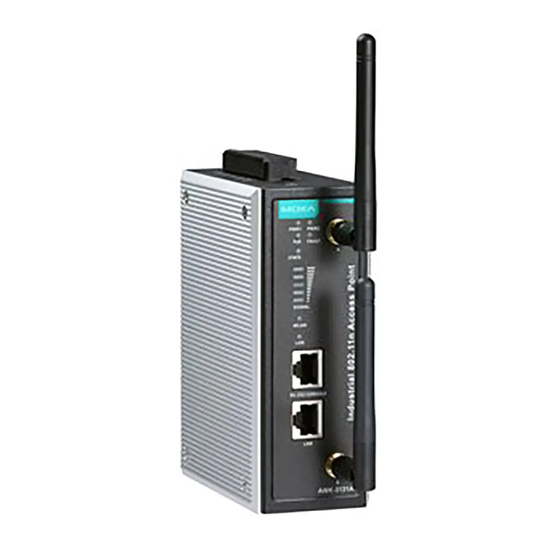
Page 3: Panel Layout Of The Awk-3131A
Panel Layout of the AWK-3131A 1. Grounding screw (M5) 2. Terminal block for PWR1,PWR2, relay, DI1, and DI2 3. Reset button 4. System LEDs: PWR1, PWR2, PoE, FAULT, and STATE LEDs 5. LEDs for signal strength 6. WLAN LED 7. Ethernet LED 8. -
Page 4: Mounting Dimensions (Unit = Mm)
DIN-Rail Mounting The aluminum DIN-rail attachment plate should be fixed to the back panel of the AWK-3131A when you take it out of the box. If you need to reattach the DIN-rail attachment plate to the AWK-3131A, make sure the stiff metal spring is situated towards the top, as shown in the figures below. -
Page 5: Wall Mounting (Optional)
STEP 2: Mounting the AWK-3131A to a wall requires 3 screws. Use the AWK-3131A device, with wall mount plates attached, as a guide to mark the correct locations of the 3 screws. The heads of the screws should be less than 6.0 mm in diameter, and the shafts should be less... -
Page 6: Wiring Requirements
Wiring Requirements WARNING Safety First! Be sure to disconnect the power cord before installing and/or wiring your Moxa AWK-3131A. WARNING Safety First! Calculate the maximum possible current in each power wire and common wire. Observe all electrical codes that dictate the maximum current allowed for each wire size. -
Page 7: Grounding The Moxa Awk-3131A
Do not use the PoE Injector. Instead, please use an IEEE 802.3af or IEEE 802.3at compliant PSE (Power Sourcing Equipment) for PoE (Power over Ethernet) devices. Grounding the Moxa AWK-3131A Grounding and wire routing help limit the effects of noise due to electromagnetic interference (EMI). Run the ground connection from the ground screw to the grounding surface prior to connecting devices. -
Page 8: Wiring The Redundant Power Inputs
4.5 lb-in (0.51 Nm). ATTENTION If the AWK-3131A is connected to a motor or other similar type of equipment, be sure to use power isolation protection. Before connecting the AWK-3131A to the DC power inputs, make sure the DC power source voltage is stable. -
Page 9: Wiring The Digital Inputs
Wiring the Relay Contact The AWK-3131A has one relay output, which consists of the two contacts of the terminal block on the AWK-3131A’s top panel. Refer to the previous section for detailed instructions on how to connect the wires to the terminal block connector, and how to attach the terminal block connector to the terminal block receptor. - Page 10 The AWK-3131A has one RS-232 (8-pin RJ45) console port located on the front panel. Use either an RJ45-to-DB9 or RJ45-to-DB25 cable to connect the Moxa AWK-3131A’s console port to your PC’s COM port. You may then use a console terminal program to access the AWK-3131A for console configuration.
-
Page 11: Led Indicators
LED Indicators The front panel of the Moxa AWK-3131A contains several LED indicators. The function of each LED is described in the table below. Color State Description Front Panel LED Indicators (System) Power is being supplied from power input 1. -
Page 12: Specifications
WLAN is not in use or not working properly LAN port’s 1000 Mbps link is active. Green Blinking Data is being transmitted at 1000 Mbps. LAN port’s 1000 Mbps link is inactive. LAN port’s 10/100 Mbps link is active. Amber Blinking Data is being transmitted at 10/100 Mbps. - Page 13 Operating Channels (central frequency) • 2.412 to 2.462 GHz (11 channels) • 5.180 to 5.240 (4 channels) • 5.260 to 5.320 (4 channels)* • 5.500 to 5.700 GHz (8 channels, excluding 5.600 to 5.640 GHz)* • 5.745 to 5.825 GHz (5 channels) •...
- Page 14 TX Transmit Power 802.11b: • Typ. 23±1.5 dBm @ 1 Mbps, Typ. 23±1.5 dBm @ 2 Mbps • Typ. 20±1.5 dBm @ 5.5 Mbps, Typ. 19±1.5 dBm @ 11 Mbps 802.11g: • Typ. 20±1.5 dBm @ 6 to 24 Mbps, Typ. 19±1.5 dBm @ 36 Mbps •...
-
Page 15: Physical Characteristics
• 802.11n (5 GHz): -70 dBm @ MCS7 20 MHz, -67 dBm @ MCS15 20 MHz -68 dBm @ MCS7 40 MHz, -66 dBm @ MCS15 40 MHz Protocol Support General Protocols Proxy ARP, DNS, HTTP, HTTPS, IP, ICMP, SNTP, TCP, UDP, RADIUS, SNMP, DHCP, LLDP, VLAN, STP/RSTP Interface... - Page 16 Details See www.moxa.com/support/warranty.aspx ATTENTION • The AWK-3131A is NOT a portable mobile device and should be located at least 20 cm away from the human body. • The AWK-3131A is NOT designed for the general public. A well-trained technician is required to deploy AWK-3131As and safely establish a wireless network.
- Page 17 Pollution Degree 2 as defined in EN 60529 and used within its rated electrical and environmental ratings. When the AWK-3131A is installed in an enclosure, the antennas must remain internal to the enclosure and not external. External antenna deployment is allowed only if the antennas are certified by C1D2, ATEX Zone 2 or IECEx.
- Page 18 WARNING EXPLOSION HAZARD Substitution of any components may impair suitability for Class I, Division 2. - 18 -...
Need help?
Do you have a question about the AWK-3131A and is the answer not in the manual?
Questions and answers