Table of Contents
Advertisement
Quick Links
Download this manual
See also:
User Manual
Advertisement
Table of Contents

Related Manuals for Moxa Technologies AWK-3131


Summary of Contents for Moxa Technologies AWK-3131
- Page 1 AWK-3131 Hardware Installation Guide Moxa AirWorks Second Edition, June 2014 2014 Moxa Inc. All rights reserved. Reproduction without permission is prohibited. P/N: 1802031310011...
-
Page 2: Package Checklist
40 MHz channel to deliver a potent combination of greater reliability and more bandwidth. The two redundant DC power inputs increase the reliability of the power supply, and the AWK-3131 can be powered via PoE to make deployment easier. The AWK-3131 can operate on either the 2.4 or 5 GHz bands and is backward-compatible with... -
Page 3: Recommended Sfp Accessories
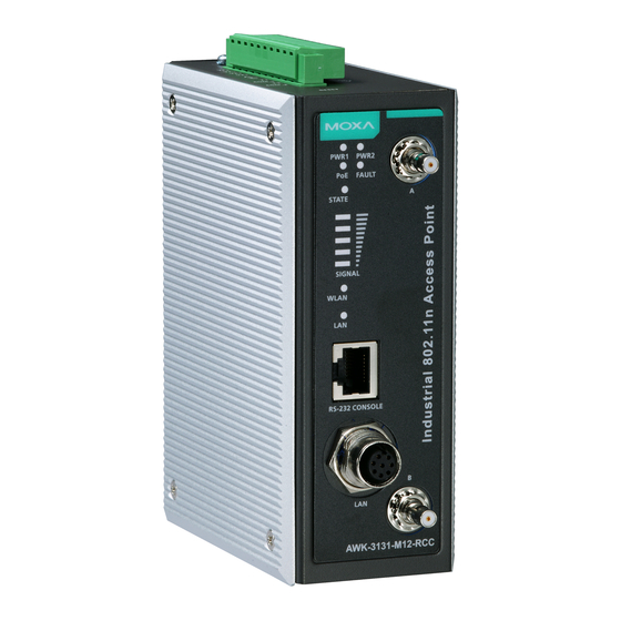
Recommended SFP Accessories SFP-1G series • SFP-1GSXLC: Small form factor pluggable transceiver with 1000BaseSX, LC, 0.5 km, 0 to 60°C • SFP-1GSXLC-T: Small form factor pluggable transceiver with 1000BaseSX, LC, 0.5 km, -20 to 75°C • SFP-1GLSXLC: Small form factor pluggable transceiver with 1000BaseLSX, LC, 2 km, 0 to 60°C •... - Page 4 Panel Layout of the AWK-3131 1. Grounding screw (M3) 2. Terminal block for PWR1,PWR2, relay, DI1, and DI2 3. Reset button 4. System LEDs: PWR1, PWR2, PoE, FAULT, and STATE LEDs 5. LEDs for signal strength 6. WLAN LED 7. Ethernet or Fiber LED 8.
-
Page 5: Mounting Dimensions (Unit = Mm)
DIN-Rail Mounting The aluminum DIN-Rail attachment plate should be fixed to the back panel of the AWK-3131 when you take it out of the box. If you need to reattach the DIN-Rail attachment plate to the AWK-3131, make sure the stiff metal spring is situated towards the top, as shown in the figures below. -
Page 6: Wall Mounting (Optional)
Wall Mounting (optional) For transportation applications that require an EN 50155 certification report, we strongly recommend the purchase of the optional AWK-3131 wallmount kit, which has passed EN 50155 testing. This wallmount kit is also convenient for other applications that require mounting the AWK-3131 to a wall. -
Page 7: Wiring Requirements
Wiring Requirements WARNING Safety First! Be sure to disconnect the power cord before installing and/or wiring your Moxa AWK-3131. WARNING Safety First! Calculate the maximum possible current in each power wire and common wire. Observe all electrical codes dictating the maximum current allowed for each wire size. -
Page 8: Wiring The Redundant Power Inputs
Wiring the Redundant Power Inputs The top two pairs of contacts of the 10-contact terminal block connector on the AWK-3131’s top panel are used for the AWK-3131’s two DC inputs. Top and front views of the terminal block connector are shown below. -
Page 9: Wiring The Relay Contact
DC power source voltage is stable. Wiring the Relay Contact The AWK-3131 has one relay output, which consists of the two contacts of the terminal block on the AWK-3131’s top panel. Refer to the previous section for detailed instructions on how to connect the wires to the terminal block connector, and how to attach the terminal block connector to the terminal block receptor. -
Page 10: Communication Connections
The AWK-3131 has one RS-232 (8-pin RJ45) console port located on the front panel. Use either an RJ45-to-DB9 or RJ45-to-DB25 cable to connect the Moxa AWK-3131’s console port to your PC’s COM port. You may then use a console terminal program to access the AWK-3131 for console configuration. -
Page 11: Led Indicators
Refer to the Pinout diagram above to see how RJ45 pins are numbered. LED Indicators The front panel of the Moxa AWK-3131 contains several LED indicators. The function of each LED is described in the table below. Color State... -
Page 12: Specifications
Specifications WLAN Interface Standards IEEE 802.11a/b/g/n for Wireless LAN IEEE 802.11i for Wireless Security IEEE 802.3 for 10BaseT IEEE 802.3u for 100BaseTX IEEE 802.3ab for 1000BaseT IEEE 802.3af for Power-over-Ethernet IEEE 802.1D for Spanning Tree Protocol IEEE 802.1w for Rapid STP IEEE 802.1Q VLAN Spread Spectrum and DSSS with DBPSK, DQPSK, CCK... - Page 13 5GHz 802.11a: • Typ. 17±1.5 dBm @ 6 to 24 Mbps • Typ. 16±1.5 dBm @ 36 to 48 Mbps • Typ. 14±1.5 dBm @ 54 Mbps 802.11n: • MCS15 20 MHz: Typ. 13 dBm (± 1.5 dBm) • MCS15 40 MHz: Typ. 12 dBm (± 1.5 dBm) RX Sensitivity 2.4GHz 802.11b:...
-
Page 14: Physical Characteristics
(RJ45-type) Fiber Ports 1, 1000BaseSFP slot Console Port RS-232 (RJ45-type) Reset Present LED Indicators PWR1, PWR2, PoE, FAULT, STATE, SIGNAL, WLAN, LAN Alarm Contact 1 relay output with current carrying capacity of 1 A @ 24 VDC Digital Inputs 2 electrically isolated inputs +13 to +30 V for state “1”... - Page 15 ATTENTION The AWK-3131 is NOT a portable mobile device and should be located at least 20 cm away from the human body. The AWK-3131 is NOT designed for the general public. To deploy AWK-3131s and establish a wireless network safely, a well-trained technician is required for installation.
- Page 16 ATTENTION For EXPLOSION-PROOF application, model AWK-3131 are designed and certified to meet ATEX, and C1D2, and shall be mounted in a suitable enclosure rate to at least IP54 and Pollution Degree 2 as defined in EN60529 and used within its rated electrical and environmental ratings.
Need help?
Do you have a question about the AWK-3131 and is the answer not in the manual?
Questions and answers