
Related Manuals for Moxa Technologies AirWorks AWK-3131A-M12-RCC-EU


Summary of Contents for Moxa Technologies AirWorks AWK-3131A-M12-RCC-EU
- Page 1 AWK-3131A-M12-RCC Quick Installation Guide Moxa AirWorks Version 3.1, January 2021 Technical Support Contact Information www.moxa.com/support 2021 Moxa Inc. All rights reserved. P/N: 1802031312033 *1802031312033*...
-
Page 2: Package Checklist
Overview Moxa’s new AWK-3131A-M12-RCC is a 3-in-1 industrial AP/client device designed specifically for rail carriage-to-carriage communication and can provide up to 300 Mbps speed with IEEE 802.11n technology. The AWK-3131A-M12-RCC combines two adjacent 20 MHz channels into a single 40 MHz channel to deliver a potent combination of greater reliability and more bandwidth. - Page 3 Step 3: Set up the computer’s IP address Set an IP address on the same subnet as the AWK-3131A-M12-RCC. Since the AWK-3131A-M12-RCC’s default IP address is 192.168.127.253, and the subnet mask is 255.255.255.0, you should set the IP address of the computer to 192.168.127.xxx and subnet mask to 255.255.255.0.
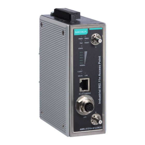
- Page 4 Panel Layout of the AWK-3131A-M12-RCC 1. Grounding screw (M5) 2. Terminal block for PWR1, PWR2, relay, DI0, and DI1 3. Reset button 4. A antenna connector 5. B antenna connector 6. System LEDs: PWR1, PWR2, PoE, FAULT, and STATE 7. Signal strength indicator 8.
-
Page 5: Mounting Dimensions (Unit = Mm)
Mounting Dimensions (unit = mm) DIN-rail Mounting The aluminum DIN-rail attachment plate should be fixed to the back panel of the AWK-3131A-M12-RCC when you take it out of the box. If you need to reattach the DIN-rail attachment plate to the AWK-3131A-M12-RCC, make sure the stiff metal spring is situated towards the top, as shown in the figures below. -
Page 6: Wall Mounting (Optional)
Wall Mounting (optional) For transportation applications that require an EN 50155 certification report, we strongly recommend the purchase of the optional AWK-3131A-M12-RCC wall-mounting kit, which has passed EN 50155 testing. This wall-mounting kit is also convenient for other applications that require mounting the AWK-3131A-M12-RCC to a wall. STEP 1: Remove the aluminum DIN-rail attachment plate... -
Page 7: Wiring Requirements
WARNING • This equipment is intended to be used in a Restricted Access Location, such as a dedicated computer room, a cabinet, or space specially reserved for device installation onboard a train. Access can only be gained by SERVICE PERSONS or by USERS who have been instructed to comply with the safety rules thereby avoiding casualties from electric shock, cutting from a sharp edge, heat from a metallic surface, and so on. - Page 8 ATTENTION This product is intended to be supplied by a Listed Power Unit marked “Class 2” or “LPS” and rated O/P: 12 to 48 VDC, minimum 6 W (12 V to 48 V), 25°C. ATTENTION Make sure the external power adapter (includes power cords and plug assemblies) provided with the unit is certified and suitable for use in your country.
-
Page 9: Wiring The Relay Contact
Wiring the Dual Power Inputs The top two pairs of contacts of the 10-contact terminal block connector on the AWK-3131A-M12-RCC’s top panel are used for the AWK-3131A-M12-RCC’s two DC inputs. Top and front views of the terminal block connector are shown below. STEP 1: Insert the negative/positive DC wires into the V-/V+ terminals. -
Page 10: Cable Holder Installation
Cable Holder Installation You can attach the cable holder to the bottom of the AWK-3131A-M12-RCC. This helps to keep cabling neat and avoid accidents that result from untidy cables. STEP 1: Screw the cable holder onto the bottom of the AWK-3131A-M12-RCC. -
Page 11: Reset Button
RS-232 Connection The AWK-3131A-M12-RCC has one RS-232 (8-pin RJ45) console port on the front panel. Use either an RJ45-to-DB9 or RJ45-to-DB25 cable to connect the AWK-3131A-M12-RCC console port to your PC’s COM port. You may then use a console terminal program to access the AWK-3131A-M12-RCC for console configuration. -
Page 12: Led Indicators
LED Indicators The front panel of the Moxa AWK-3131A-M12-RCC contains several LED indicators: Color State Description Power is being supplied from power input 1. PWR1 Green Power is not being supplied from power input 1. Power is being supplied from power input 2. -
Page 13: Specifications
Specifications WLAN Interface Standards IEEE 802.11a/b/g/n for Wireless LAN IEEE 802.11i for Wireless Security IEEE 802.3 for 10BaseT IEEE 802.3u for 100BaseTX IEEE 802.3ab for 1000BaseT IEEE 802.3af for Power-over-Ethernet IEEE 802.1Q for VLAN Spread Spectrum • DSSS with DBPSK, DQPSK, CCK and Modulation •... - Page 14 802.11g: • Typ. 23±1.5 dBm @ 6 to 24 Mbps • Typ. 21±1.5 dBm @ 36 Mbps • Typ. 19±1.5 dBm @ 48 Mbps • Typ. 18±1.5 dBm @ 54 Mbps 802.11n (2.4 GHz): • Typ. 23±1.5dBm @ MCS0 20 MHz •...
- Page 15 • Typ. 19±1.5dBm @ MCS12 20 MHz • Typ. 19±1.5dBm @ MCS13 20 MHz • Typ. 18±1.5dBm @ MCS14 20 MHz • Typ. 18±1.5dBm @ MCS15 20 MHz • Typ. 23±1.5dBm @ MCS0 40 MHz • Typ. 20±1.5dBm @ MCS1 40 MHz •Typ.
- Page 16 • -76 dBm @ MCS4 40 MHz • -73 dBm @ MCS5 40 MHz • -69 dBm @ MCS6 40 MHz • -67 dBm @ MCS7 40 MHz • -93 dBm @ MCS8 40 MHz • -88 dBm @ MCS9 40 MHz •...
- Page 17 Protocol Support General Protocols Proxy ARP, DNS, HTTP, HTTPS, IP, ICMP, SNTP, TCP, UDP, RADIUS, SNMP, PPPoE, DHCP Interface AP-only Protocols ARP, BOOTP, DHCP Interface Connector for QMA (female) External Antennas M12 Ports 1, 10/100/1000BaseT(X) auto negotiation speed, F/H duplex mode, and auto MDI/MDI-X connection Console Port RS-232 (RJ45-type) LED Indicators...
- Page 18 Singapore: IDA* Rail Traffic EN 50155**, EN 50121-1/4, EN 45545-2 Complies with a portion of EN 50155 specifications. Note: Please check Moxa’s website for the most up-to-date certification status. MTBF (mean time between failures) Time 742,649 hrs Standard Telcordia SR332 Warranty Warranty Period 5 years...
Need help?
Do you have a question about the AirWorks AWK-3131A-M12-RCC-EU and is the answer not in the manual?
Questions and answers