Moxa Technologies AWK-3131A Quick Installation Manual
Hide thumbs
Also See for AWK-3131A:
- User manual (109 pages) ,
- Quick installation manual (19 pages) ,
- User manual (109 pages)
Table of Contents
Advertisement
Quick Links
Download this manual
See also:
User Manual
Quick Installation Guide
Moxa Americas:
Toll-free: 1-888-669-2872
Tel:
1-714-528-6777
Fax:
1-714-528-6778
Moxa Europe:
Tel:
+49-89-3 70 03 99-0
Fax:
+49-89-3 70 03 99-99
Moxa India:
Tel:
+91-80-4172-9088
Fax:
+91-80-4132-1045
AWK-3131A
Moxa AirWorks
Edition 7.1, October 2018
Technical Support Contact Information
www.moxa.com/support
2018 Moxa Inc. All rights reserved.
Moxa China (Shanghai office):
Toll-free: 800-820-5036
Tel:
+86-21-5258-9955
Fax:
+86-21-5258-5505
Moxa Asia-Pacific:
Tel:
+886-2-8919-1230
Fax:
+886-2-8919-1231
P/N: 1802031311017
*1802031311017*
Advertisement
Table of Contents

Related Manuals for Moxa Technologies AWK-3131A


Summary of Contents for Moxa Technologies AWK-3131A
- Page 1 AWK-3131A Quick Installation Guide Moxa AirWorks Edition 7.1, October 2018 Technical Support Contact Information www.moxa.com/support Moxa Americas: Moxa China (Shanghai office): Toll-free: 1-888-669-2872 Toll-free: 800-820-5036 Tel: 1-714-528-6777 Tel: +86-21-5258-9955 Fax: 1-714-528-6778 Fax: +86-21-5258-5505 Moxa Europe: Moxa Asia-Pacific: Tel: +49-89-3 70 03 99-0...
-
Page 2: Table Of Contents
Overview ................- 3 - Hardware Setup ..............- 3 - Package Checklist ............... - 3 - Panel Layout of the AWK-3131A ........... - 4 - Mounting Dimensions ............- 5 - DIN-Rail Mounting .............. - 5 - Wall Mounting (Optional) ............. - 6 - Wiring Requirements ............ -
Page 3: Overview
40 MHz channel to deliver a potent combination of greater reliability and more bandwidth. The two redundant DC power inputs increase the reliability of the power supply, and the AWK-3131A can be powered via PoE to make deployment easier. The AWK-3131A can operate on either the 2.4 or the 5 GHz band and is backwards-compatible... -
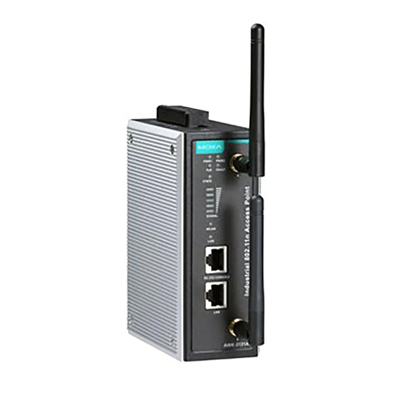
Page 4: Panel Layout Of The Awk-3131A
Panel Layout of the AWK-3131A 1. Grounding screw (M5) 2. Terminal block for PWR1,PWR2, relay, DI1, and DI2 3. Reset button 4. System LEDs: PWR1, PWR2, PoE, FAULT, and STATE LEDs 5. LEDs for signal strength 6. WLAN LED 7. Ethernet LED 8. -
Page 5: Mounting Dimensions
DIN-Rail Mounting The aluminum DIN-rail attachment plate should be fixed to the back panel of the AWK-3131A when you take it out of the box. If you need to reattach the DIN-rail attachment plate to the AWK-3131A, make sure the stiff metal spring is situated towards the top, as shown in the figures below. -
Page 6: Wall Mounting (Optional)
M3 screws, as shown in the adjacent diagrams. STEP 2: Mounting the AWK-3131A to a wall requires 3 screws. Use the AWK-3131A device, with wall-mounting plates attached, as a guide to mark the correct locations of the 3 screws. The heads of the screws should be less than 6.0 mm in diameter, and the shafts should be less than 3.5... -
Page 7: Wiring Requirements
WARNING Safety First! Be sure to disconnect the power cord before installing and/or wiring your AWK-3131A. Calculate the maximum possible current in each power wire and common wire. Observe all electrical codes that dictate the maximum current allowed for each wire size. If the current goes above the maximum ratings, the wiring could overheat, causing serious damage to your equipment. -
Page 8: Grounding The Awk-3131A
DO NOT use a PoE Injector. Instead, use an IEEE 802.3af or IEEE 802.3at compliant PSE (Power Sourcing Equipment) for PoE (Power over Ethernet) devices. Grounding the AWK-3131A Grounding and wire routing help limit the effects of noise due to electromagnetic interference (EMI). Run the ground connection from the ground screw to the grounding surface prior to connecting devices. -
Page 9: Wiring The Redundant Power Inputs
12-28 AWG (3.31-0.0804 mm²) and a torque value of 4.5 lb-in (0.51 Nm). ATTENTION If the AWK-3131A is connected to a motor or other similar type of equipment, be sure to use power isolation protection. Before connecting the AWK-3131A to the DC power inputs, make sure the DC power source voltage is stable. -
Page 10: Wiring The Digital Inputs
Cable Holder Installation Attach the cable holder to the bottom of the AWK-3131A to keep cabling neat and avoid accidents that result from untidy cables. STEP 1: Screw the cable holder onto the bottom of the AWK-3131A. -
Page 11: 1000Baset Ethernet Port Connection
The AWK-3131A has one RS-232 (8-pin RJ45) console port located on the front panel. Use either an RJ45-to-DB9 or RJ45-to-DB25 cable to connect the AWK-3131A’s console port to your PC’s COM port. You may then use a console terminal program to access the AWK-3131A for console configuration. -
Page 12: Led Indicators
LED Indicators The front panel of the AWK-3131A contains several LED indicators. The function of each LED is described in the table below: Color State Description Front Panel LED Indicators (System) Power is on (power input 1) PWR1 Green Power is not being supplied. -
Page 13: Specifications
Storage Temperature -40 to 85°C (-40 to 185°F) ATTENTION The AWK-3131A is NOT a portable mobile device and should be located at least 20 cm away from the human body. The AWK-3131A is NOT designed for the general public. To... - Page 14 60664-1 and used within its rated electrical and environmental ratings. When the AWK-3131A is installed in an enclosure, the antennas must remain internal to the enclosure and not external. External antenna deployment is allowed only if the antennas are certified by C1D2, ATEX Zone 2 or IECEx.
-
Page 15: Software Setup
Substitution of any component may impair suitability for Class I, Division 2. Software Setup This section covers the software setup for the AWK-3131A. How to Access the AWK Before installing the AWK device (AWK), make sure that all items in the package checklist are provided in the product box. -
Page 16: First-Time Quick Configuration
First-Time Quick Configuration After successfully accessing the AWK, refer to the appropriate subsection below to quickly set up a wireless network. NOTE Ensure that there are no IP address conflicts when you configure more than one AWK on the same subnet. Point-to-Multipoint Scenario (AP/Client Mode) Configuring the AWK as an AP •... - Page 17 Step 3: Set the RF type and Channel for the AWK. • Go to Wireless LAN Setup WLAN Basic WLAN Setup. We recommend that you choose the RF type 5 GHz for a relative clean medium with minimum interference. For the Channel setting, we recommend that you choose a channel other than the default channel to avoid interference.
-
Page 18: Point-To-Point Scenario (Master/Slave Mode)
Step 3: Set the RF type and Channel settings for the AWK. • On the Wireless LAN Setup WLAN Basic WLAN Setup page, edit the RF type and Channel settings. Click Submit to apply the changes, and restart the AWK in client mode to complete the configuration process. - Page 19 Configuring the AWK as a Slave • Step 1: Set the operation mode of the AWK to Slave mode. Go to Wireless LAN Setup Operation Mode, set the operation mode to Slave, and then click Submit to apply the change. Step 2: Link to an existing SSID.
Need help?
Do you have a question about the AWK-3131A and is the answer not in the manual?
Questions and answers