Table of Contents
Advertisement
Quick Links
Advertisement
Table of Contents

Related Manuals for Moxa Technologies AWK-3131A-M12-RTG-EU-T


Summary of Contents for Moxa Technologies AWK-3131A-M12-RTG-EU-T
- Page 1 AWK-3131A-RTG Series Quick Installation Guide Industrial IEEE 802.11n wireless AP/client Version 2.1, January 2021 Technical Support Contact Information www.moxa.com/support 2021 Moxa Inc. All rights reserved. P/N: 1802031312012 *1802031312012*...
-
Page 2: Package Checklist
Overview The AWK-3131A-RTG Series 3-in-1 industrial AP/client devices are designed specifically for train-to-ground communication for trains moving at speeds of up to 120 km/h. The AWK-3131A-RTG is compliant with mandatory sections of the EN 50155 standard, covering operating temperature, power input voltage, surge, ESD, and vibration, as well as conformal coating and power insulation, making the AWK-3131A-RTG suitable for a variety of industrial applications. - Page 3 Step 3: Set up the computer’s IP address Update the computer’s IP address so that the computer is on the same subnet as the AWK-3131A-RTG. Since the AWK-3131A-RTG’s default IP address is 192.168.127.253, and the subnet mask is 255.255.255.0, you should set the IP address of the computer to 192.168.127.xxx and subnet mask to 255.255.255.0.
-
Page 4: Panel Layout Of The Awk-3131A-M12-Rtg
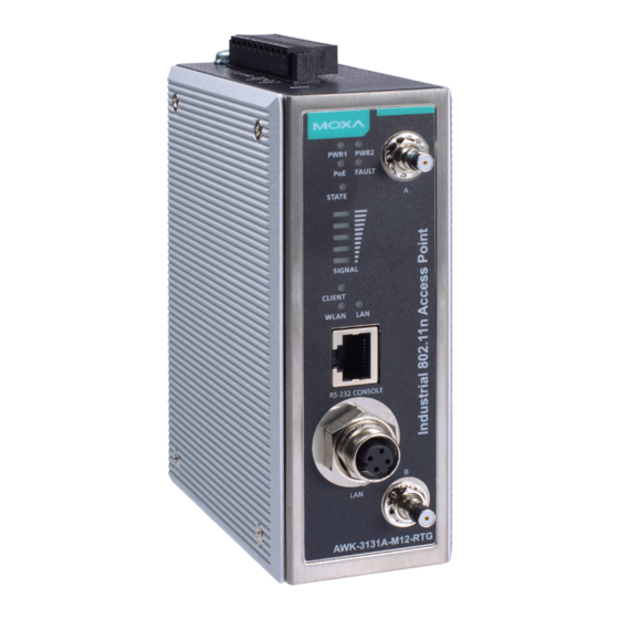
Panel Layout of the AWK-3131A-M12-RTG 1. Grounding screw (M5) 2. Terminal block for PWR1, PWR2, relay, DI0, and DI1 3. Reset button 4. System LEDs: PWR1, PWR2, PoE, FAULT, and STATE LEDs 5. LEDs for signal strength 6. LEDs: CLIENT, WLAN, and LAN 7. -
Page 5: Panel Layout Of The Awk-3131A-Ssc-Rtg
Panel Layout of the AWK-3131A-SSC-RTG 1. Grounding screw (M5) 2. Terminal block for PWR1, PWR2, relay, DI0, and DI1 3. Reset button 4. System LEDs: PWR1, PWR2, FAULT, and STATE LEDs 5. LEDs for signal strength 6. LEDs: CLIENT, WLAN, and 100M 7. -
Page 6: Mounting Dimensions (Unit = Mm)
Mounting Dimensions (unit = mm) AWK-3131A-M12-RTG AWK-3131A-SSC-RTG DIN-rail Mounting The aluminum DIN-rail attachment plate should be fixed to the back panel of the AWK-3131A-RTG when you take it out of the box. If you need to reattach the DIN-rail attachment plate to the AWK-3131A-RTG, make sure the stiff metal spring is situated towards the top, as shown in the figures below: - 6 -... -
Page 7: Wall Mounting (Optional)
STEP 1: STEP 2: Insert the top of the DIN rail into the The DIN-rail attachment unit will slot just below the stiff metal spring. snap into place as shown below. To remove the AWK-3131A-RTG from the DIN rail, simply reverse the steps 1 and 2. -
Page 8: Wiring Requirements
STEP 3: Once the screws are fixed into the wall, insert the four screw heads through the large opening of the keyhole-shaped apertures, and then slide the AWK-3131A-RTG downwards, as indicated to the right. Tighten the four screws for added stability. -
Page 9: Grounding The Moxa Awk-3131A-Rtg
You should also pay attention to the following items: • Use separate paths to route wiring for power and devices. If power wiring and device wiring paths must cross, make sure the wires are perpendicular at the intersection point. NOTE: Do not run signal or communications wiring and power wiring in the same wire conduit. -
Page 10: Wiring The Redundant Power Inputs
Installing a DC/DC power isolator, in between the two equipment, is recommended to isolate the transient effect and to ensure a stable power input for the AWK. Wiring the Redundant Power Inputs The top two pairs of contacts of the 10-contact terminal block connector on the AWK-3131A-RTG’s top panel are used for the AWK-3131A-RTG’s two DC inputs. -
Page 11: Wiring The Digital Inputs
Wiring the Digital Inputs The AWK-3131A-RTG has two sets of digital inputs: DI0 and DI1. Each DI comprises two contacts of the 10-pin terminal block connector on the AWK-3131A-RTG’s top panel. Refer to the “Wiring the Redundant Power Inputs” section for detailed instructions on how to connect the wires to the terminal block connector, and how to attach the terminal block connector to the terminal block receptor. -
Page 12: 10/100Baset(X) Ethernet Port Connection
If you make your own cable, we suggest labeling the two sides of the same line with the same letter (A-to-A and B-B, as illustrated below, or (A1-to-A1, B1-to-B2, etc.). SC-Port Pinouts SC-Port to SC-Port Cable Wiring ATTENTION This is a Class 1 Laser/LED product. To avoid causing serious damage to your eyes, do not stare directly into the laser beam. -
Page 13: Led Indicators
Console Pinouts for 10-pin or 8-pin RJ45 10-Pin 8-Pin Description Connector Connector – – – – ATTENTION For railway rolling stock applications, the AWK-3131A-RTG must use a galvanically isolated power supply that is compliant with the EN 50155 standard. LED Indicators The front panel of the Moxa AWK-3131A-RTG contains several LED indicators. -
Page 14: Specifications
Color State Description Signal level SIGNAL Green (for Client and Client-Router (5 LEDs) mode only) The AWK is functioning in Client or Client-Router Mode. CLIENT Green MODE The AWK is not functioning in Client or Client-Router Mode. WLAN is in use. WLAN Amber WLAN is not in use.
Need help?
Do you have a question about the AWK-3131A-M12-RTG-EU-T and is the answer not in the manual?
Questions and answers