Table of Contents
Advertisement
Installation and
Operation Manual
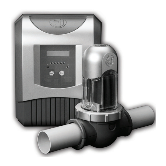
AquaPure
Chlorine Generating Device
Dual Voltage 240V/120V
APURE35
FOR YOUR SAFETY - This product must be installed and serviced by professionals who are
qualified in pool/spa product installation and service. Improper installation and/or operation
can create an unwanted electrical hazard which can cause serious injury, property damage, or
death. Improper installation and/or operation will void the warranty.
This manual contains important information about the installation, operation and safe use of
this product. This information should be given to the owner/operator of this equipment.
Series
WARNING
Advertisement
Table of Contents

Related Manuals for Jandy APURE35


Summary of Contents for Jandy APURE35
- Page 1 AquaPure Series Chlorine Generating Device Dual Voltage 240V/120V APURE35 WARNING FOR YOUR SAFETY - This product must be installed and serviced by professionals who are qualified in pool/spa product installation and service. Improper installation and/or operation can create an unwanted electrical hazard which can cause serious injury, property damage, or death.
- Page 2 Page 2...
-
Page 3: Table Of Contents
Page 3 Table of Contents Section 1. Important Safety Instructions ..5 Section 6. Maintenance Instructions .... 25 6.1 Daily ..............25 Section 2. System Description ...... 8 6.2 Monthly ............. 25 6.3 Cleaning the Cell ..........26 2.1 Product Specifications ........8 6.4 Winterizing ............ - Page 4 Page 4 List of Figures List of Tables Figure 1. Example of Installation ......8 Table 1. Approximate Pounds and Kilograms of Salt Needed to Obtain Figure 2. Carton Contents ........9 4,000 ppm (4.0 gpl) ....... 21 Figure 3. Installation Requirements ...... 10 Table 2. Approximate Pounds and Kilograms of Figure 4. Installation Requirements ...... 11 Stabilizer Needed to Obtain 50 ppm ..22 Figure 5. Attaching the Power Pack ..... 11 Figure 6. Disassemble Cell ........
-
Page 5: Section 1. Important Safety Instructions
When installing and using this electrical equipment, basic safety precautions should always be followed, including the following: WARNING EQUIPMENT UNDER PRESSURE: Always turn pump off prior to installing or servicing the power pack or cell. Your pump/filter system is operated under pressure and the pressure must be released before you begin work. Please see your pump/filter owner’s manual for further instructions. WARNING To reduce the risk of electric shock, fire or injury, service should only be attempted by a qualified pool service professional. WARNING Jandy® AquaPure® Ei chlorine generating devices are designed for domestic (residential) swimming pool use only. Contrary use could affect performance, void warranty, and may result in property damage, serious injury, or death. • Operating a chlorine generator without water flowing through the cell may cause a build up of flammable gases, resulting in fire or explosion. • Keep equipment out of reach of children. • A damaged supply cord should only be replaced by the manufacturer, service agent or electrician. • When installing and using this electrical equipment, always follow basic safety precautions. • Before performing installation, disconnect all power. - Page 6 Page 6 WARNING • The power pack must be be installed at least 5 ft. (1.5 m) vertically off the ground. • In the US, the power pack must be be installed at least 5 ft. (1.5 m) from the inside wall of your swimming pool or spa; in Canada, the power pack must be be installed at least 10 ft. (3 m) from the inside wall of your swimming pool or spa. WARNING Operating the Jandy® AquaPure® Ei chlorine generating device without water flow through the electrolytic cell can cause a buildup of flammable gasses which can result in FIRE OR EXPLOSION. WARNING This appliance is not intended for use by persons (including children) with reduced physical, sensory or mental capabilities, or lack of experience and knowledge, unless they have been given supervision or instruction concerning use of the appliance by a person responsible for their safety. WARNING To reduce the risk of injury, do not remove the suction fittings of your spa or hot tub. Never operate a spa or hot tub if the suction fittings are broken or missing. Never replace a suction fitting with one rated less than the flow rate marked on the equipment assembly. WARNING PREVENT CHILD DROWNING: Do not let anyone, especially small children, sit, step, lean or climb on any equipment installed as part of your pool’s operational system. Locate the components of your operational system at least 3 feet from the pool so children cannot use the equipment to access the pool and be injured or drown. WARNING Prolonged immersion in hot water may induce hyperthermia. Hyperthermia occurs when the internal temperature of the body reaches a level several degrees above the normal body temperature of 98.6°F (37°C). The symptoms of hyperthermia include dizziness, fainting, drowsiness, lethargy, and an increase in the internal temperature of the body. The effects of hyperthermia include: • Unawareness of impending danger • Failure to perceive heat • Failure to recognize the need to exit spa • Physical inability to exit spa • Fetal damage in pregnant women...
- Page 7 • Prolonged immersion in a spa or hot tub may be injurious to your health. • Do not permit any electric appliance (such as a light, telephone, radio, or television) within 5 ft. (1.52 m) of a spa or hot tub. • The use of alcohol, drugs or medication can greatly increase the risk of fatal hyperthermia in hot tubs and spas. • Water temperature in excess of 100°F (38°C) may be hazardous to your health. CAUTION This device is intended for use with permanent swimming pools and may also be used with hot tubs and spas if so marked. Do not use with storable pools. A permanently-installed pool is constructed in or on the ground or in a building such that it cannot be readily dissembled for storage. A storable pool is constructed so that it is capable of being readily disassembled for storage and reassembled to its original integrity. CAUTION It is important to note that certain materials used in and around swimming pools and spas may not be compatible with chemicals commonly used to purify pool and spa water (e.g. acids, chlorine, salt, stabilizers, etc.). Zodiac Pool Systems, Inc. does not warrant or guarantee that the chlorinated water generated by the Jandy® AquaPure® Ei chlorine generating device will not damage or destroy certain types of plants, decking, coping and other materials in and around your pool and/or spa. Before selecting materials to be used in and around your pool and/or spa, please discuss all options with your contractor to assess the compatibility of such materials and chemicals. When mixing acid with water, ALWAYS ADD ACID TO WATER. NEVER ADD WATER TO ACID. Some helpful considerations may include: • Choosing plants that can withstand splash out of pool water containing chlorine and/or salt and other water purification chemicals. • All metal components used in and around a pool should be of a high grade, quality stainless steel. • Careful selection of masonry products. The porosity and hardness of natural stones varies greatly. Therefore we recommend you consult with your builder or stone contractor on the best choice for stone materials around your pool or spa. • Sealing all masonry products. Professionals in the stone industry specify that even natural stone, especially when used outdoors, be sealed to prevent weathering, staining, and premature degradation. Consult with your stone or...
-
Page 8: Section 2. System Description
Input Freq: 47~63 Hz Required Salt Level: 4,000 ppm (4.0 gpl) Output Voltage: 25V DC (max) Maximum water volume treated: Output Current (adjustable by switch): APURE35 - 35,000 gal. (132,000 L) APURE35 - 5A DC Chlorine Output: Dimensions: APURE35 - 0.62 oz. (17.5 g) per hour Power Pack (L x W x H): 10 in. x 4.5 in. x 13 in. Electrolytic Cell (L x W x H): 6.5 in. x 5.5 in. x 12 in. -
Page 9: Product Contents
Series Chlorine Generating Device Dual Voltage 240V/120V APURE25 APURE35 WARN ING FOR YOUR SAFETY - This product must be installed and serviced by professionals who are qualifi ed in pool/spa product installation and service. Improper installation and/or operation can create an un wanted electrical hazard which can cause serious injury, property damage, or death. -
Page 10: Section 3. Installation Instructions
The Jandy AquaPure Ei chlorine generating device must be installed Pack horizontally with the cell above the pipe to avoid buildup of flammable gases which can result in FIRE OR EXPLOSION. The installation requirements for the Jandy AquaPure Ei chlorine generating device are as follows: • The power pack must be be installed at least 5 ft. (1.5 m) vertically off 15 ft. (4.6 m) MAX the ground. -
Page 11: Installing The Power Pack And Cell
Page 11 3.3 Installing the Power Pack and Cell WARNING To avoid property damage, serious injury or death, do not operate the electrolytic cell without water circulation. A buildup of flammable gasses which can result in FIRE OR EXPLOSION. 1. Ensure placement of the cell and the power pack will meet all the installation requirements outlined in Section 3.2. 2. Screw the power pack bracket into position ensuring it is no more than 15 ft. (4.6 m) from the cell (see Figure 4 and 5). 3. Position the power pack in place by aligning the bracket with the corresponding thru-holes (see Figure 5). 4. Wire the power pack to a power source and, if available, an AquaLink® RS Control System or PDA (see Sections 3.4 - 3.6). -
Page 12: Figure 10. Attaching Cell Clamps
Page 12 10. Verify the gasket is attached to the upper clamp. The curved side of the gasket must be pointing down so that it will create a seal with the pipe. 11. Secure the clamps, pipe spacer, and gasket around the pipe as shown (see Figure 10) making sure the flow arrows on the clamp point in the direction of the water flow (see Figure 11). Make sure the two (2) clips on the sides of the clamp are snapped into place. 12. -
Page 13: Wiring The Power Pack To Power Source
Page 13 3.4 Wiring the Power Pack to Power Source WARNING When using electrical products, basic precautions should always be followed, including the following: • DANGER: RISK OF ELECTRIC SHOCK WHICH CAN RESULT IN SERIOUS INJURY OR DEATH. Before attempting installation or service, ensure that all power to the device is disconnected/turned off at the circuit breaker. Connect only to a circuit protected by a ground-fault circuit-interrupter (GFCI). • Grounding is required. The unit should be installed by a qualified service representative and should be properly grounded and bonded (See Section 3.5, Earth Bonding). • Install to permit access for servicing. • Please read all cautions and safety instructions in the Important Safety Instructions section. Before attempting any electrical wiring, be sure to read and follow safety instructions. Wiring should only be attempted by a qualified professional. 1. -
Page 14: Connection To An Aqualink® Rs Control System Or Pda (Optional)
Page 14 3.6 Connection to an AquaLink® RS Control System or PDA (Optional) The Jandy® AquaLink RS or PDA is a multi-function pool controller which can fully control the function of the Jandy AquaPure® Ei chlorine generating device. Adjustment of the chlorine production rate can be controlled from the main menu of the Jandy AquaLink RS or PDA. The AquaLink RS or PDA offers individual pool and spa settings for output percentage. Refer to the AquaLink RS or PDA Owner’s Manual for more information. NOTE The Jandy AquaPure Ei chlorine generating device will communicate with all AquaLink models Rev. K or later. 3.6.1 Setting the Controller Type on the Power Pack Before wiring to the AquaLink RS Control System, the controller type must be set on the power pack to allow communication between the power pack and the AquaLink RS Control System or PDA. The default controller type setting is Jandy L/M. NOTE: The controller type must be set before making the wiring connection between the power pack and the AquaLink otherwise the power pack may be locked out of the AquaLink. To set the controller type: 1. Turn the power pack on by pressing the ON/OFF button. -
Page 15: Figure 19. Accessing And Wiring To The Power Pcb
Page 15 3. Remove the white cap covering the comm hole (see Figure 19). 4. Thread the controller cable through the hole. A grommet may be necessary depending on the size of the cable being used. 5. Attach a cable tie to the controller cable as shown (see Figure 19). Comm Hole Cable Tie Figure 19. Accessing and Wiring to the Power PCB 6. In the AquaLink® RS or PDA power center, wire the power pack directly to the LOAD SIDE of the filter pump relay (see Figure 20). AquaLink RS or PDA Power Center 240 VAC 120 VAC... -
Page 16: Testing The Connection
Page 16 7. The Jandy® AquaLink® RS or PDA and power pack use a four (4) wire connection to communicate and can be wired up to 500 feet apart. Any outdoor rated four conductor cable, minimum 22 AWG, can be used. Locate the appropriate screw terminals on the circuit board and wire the power pack to the AquaLink RS or PDA red 4-pin terminal bar (see Figure 21). NOTE The screw terminals on the AquaLink RS or PDA are removable to aid in installation. Power Pack Red, 4-Pin Terminal Bar 4 3 2 1 OPTIONAL Jandy Power Center Figure 21. -
Page 17: Bypass Plumbing Instructions
Page 17 3.7 Bypass Plumbing Instructions The maximum flow rate for the cell is 92 gpm. If flow rate exceeds 92 gpm, the cell MUST be plumbed on by-pass (see Figure 22). A control valve must be installed to regulate the flow through the cell. It can be installed on the inlet side of the cell or between the inlet and discharge side of the bypass piping. The proper flow will be achieved by adjusting the handle of the valve until the red “No Flow” light has turned off and all large air bubbles are cleared from the cell. To common The cell must be installed as the last piece of power source equipment in the circulation plumbing system Power Pack... -
Page 18: Section 4. Pool Water Preparation
One (1) unit per 35,000 gal. (up to 132,000 L) (See General Rule of Sizing notes below) General Rule of Sizing: In areas with year-round use and high water temperatures, such as Florida, Texas, Arizona, Las Vegas and Southern California, the following must be considered: Year Round Use: Up-sizing the Jandy® AquaPure® Ei chlorine generating device or adding more than one unit may be recommended for pools that are close to the maximum size and used year round. Please consult your pool professional. High Water Temperatures: Because chlorine demand increases with the rise of water temperature, adjustments must be made in order to keep up with chlorine demand. In hot summer months, where the water temperature rises above 85ºF, you must increase the pump run time and increase the percentage (%). -
Page 19: Optimum Pool Water Conditions
In accordance with Association of Pool and Spa Professionals (APSP) standards, we recommend the following water balance conditions be maintained on an on-going basis to protect the pool finish and the equipment and to ensure the pleasing appearance of the water. The Jandy AquaPure Ei is warranted to operate properly only if the following conditions are met: Free Chlorine 1.0 - 3.0 ppm. Continuous exposure to levels above 3.0 ppm may cause... -
Page 20: Chlorine Testing
4.7.2 What Type of Salt to Use • The purer the salt, the better the life and performance of the electrolytic cell. Use a salt that is at least 99.8% pure NaCl. The salt is an evaporated, granulated, food quality, non-iodized salt. Consult your salt supplier. • Avoid using salt with anti-caking agents (sodium ferrocyanide, also known as YPS or yellow prussiate of soda) that could cause some discoloration of fittings and surface finishes in pool. • Water conditioning salt pellets are compressed forms of evaporated salt and may be used but will take longer to dissolve. • Do not use calcium chloride as a source of salt. Use sodium chloride only. • Do not use rock salt because insoluble impurities mixed with the rock salt can shorten the life of the unit. CAUTION It is important to note that certain materials used in and around swimming pools and spas may not be compatible with chemicals commonly used to purify pool and spa water (e.g. acids, chlorine, salt, stabilizers, etc.). Zodiac Pool Systems, Inc. does not warrant or guarantee that the chlorinated water generated by the Jandy® AquaPure® Ei chlorine generating device will not damage or destroy certain types of plants, decking, coping and other materials in and around your pool and/or spa. Before selecting materials to be used in and around your pool and/or spa, please discuss all options with your contractor to assess the compatibility of such materials and chemicals. Some helpful considerations may include: • Choosing plants that can withstand splash out of pool water containing chlorine and/or salt and other water purification chemicals. • All metal components used in and around a pool should be of a high grade, quality stainless steel. • Careful selection of masonry products. The porosity and hardness of natural stones varies greatly. Therefore we recommend you consult with your builder or stone contractor on the best choice for stone materials around your pool or spa. • Sealing all masonry products. Professionals in the stone industry specify that even natural stone, especially when used outdoors, be sealed to prevent weathering, staining, and premature degradation. Consult with your stone or... -
Page 21: How Much Salt To Use
Page 21 4.7.3 How Much Salt to Use Use salinity test strips, a TDS/salinity meter, or another reliable method to test the salinity of the pool water. Once the existing salinity has been established, use Table 1 to determine the amount of salt to add to reach the desired level. Be conservative when adding salt as it is easier to add more if needed than it is to dilute if there is too much salt. • 4,000 ppm of salt is recommended for optimum water conditions. • Low salt concentration below 3,000 ppm will cause premature cell failure. • High salt concentration above 6,000 ppm may cause corrosion damage to pool fixtures. 4.7.4 How to Add Salt to the Pool 1. - Page 22 Page 22 Table 2. Aproximate Pounds and Kilograms of Stabilizer Needed to Obtain 50 ppm Current Pool/Spa Size US Gallons (Litres) Cyanuric Acid 10,000 g (38,000 L) 15,000 g (57,000 L) 20,000 g (76,000 L) 25,000 g (95,000 L) 30,000 g (114,000 L) 35,000 g (132,000 L) Level - ppm 4.2 lbs (1.9 kgs)
-
Page 23: Section 5. Operating Instructions
On/Off Output Figure 24. Control Panel on the Power Pack 5.2 Turning Power Pack On/Off (Manually) To turn the Jandy® AquaPure® Ei chlorine generating device on or off press the button. NOTE: Because the power pack is wired to the pump’s power source, the power pack can only be turned on when the pump is turned on. 5.3 Turning Power Pack On/Off (Using the Pump’s External Timer) If the power pack is wired to the pump’s external timer and the power to the power pack is on, the power pack will automatically turn on and off when the pump turns on and off (see Section 3.3). When the power pack is wired as such, the only setting that must be set manually is the chlorine output level (see Section 5.4). -
Page 24: Connection To An Aqualink® Rs / Pda Control System
Page 24 5.5 Connection to an AquaLink® RS / PDA Control System The Jandy® AquaPure® Ei chlorine generating device can be connected to an AquaLink RS or PDA Control System. See Section 3.5 and 3.6. For detailed instructions for the AquaLink RS or PDA Control System, see the respective manuals. 5.6 Polarity Reversal The Jandy AquaPure Ei chlorine generating device is a reversable polarity cell which means that for every five (5) hours of operation the cell will switch its polarity to help prevent any build up of calcium on the cell plates. This is sometimes referred to as the automated cell cleaning feature. -
Page 25: Section 6. Maintenance Instructions
Page 25 Section 6. Maintenance Instructions Before servicing the Jandy® AquaPure® Ei chlorine generating device please ensure you have read and understood the Important Safety Instructions section. Important: Always test the chlorine levels of your pool before each use. 6.1 Daily 1. Chlorine Test. Test pool water chlorine level with a reliable test kit. Maintain an ideal range by adjusting the chlorine output level on the power pack (see Section 5.4). The recommended free chlorine level is 1.0 - 3.0 ppm. NOTE It is recommended that chlorine test samples be taken from two (2) places, one (1) at the pool return line, the other well away from the pool return line. Compare the two (2) samples. A higher level should be found at the pool return line. The higher level at the pool return line indicates the system is producing... -
Page 26: Cleaning The Cell
The power pack has an automatic cell cleaning feature (polarity reversing) that removes scale deposits from the cell (see Section 5.6). Scale will form in excessively hard water or from pool water that is out of balance and in a scaling condition. Following the installation of the Jandy® AquaPure® Ei chlorine generating device, check the cell once a month for signs of scale. If the cell has a tendency to scale, it is recommended that every month the cell be removed and inspected for scale formation and/or debris. Some filters allow debris to pass through to the cell which could lodge between the plates... -
Page 27: Winterizing
Page 27 6.4 Winterizing Very little chlorine is needed in cold water. Below 51°F (11°C), chlorine production is not permitted; operating the chlorinator in cold water might result in over-chlorinated pool water. If preventative measures are not taken, freezing water may cause severe damage to the cell. Prevent freeze damage to the cell by running pump continuously or winterize pool by draining water from pump, filter, and all intake and return lines. Remove the cell, clean and store it indoors. Coil the cell leads, wrap in plastic and tape to the power pack. An optional winterizing cap is available to replace the cell during winterizing or cell maintenance. This will enable pool pump to circulate water with the cell out the of line. When a FREEZE CONTROLLER is used on pump equipment and the chlorinator is run through the winter, turn the CHLORINE PRODUCTION down to 10 - 20%. Otherwise, chlorine production will exceed the recommended level of 1 - 3 ppm. -
Page 28: Section 7. Troubleshooting
Page 28 Section 7. Troubleshooting WARNING Always turn pump off prior to attempting service or repair Your pump and filter system is operated under pressure and pressure must be released before you begin to avoid system damage or personal injury. Open the air relief valve on your pool filter to release the pressure in the system. 7.1 Problems and Corrective Action Problem Possible Cause Corrective Action Low or no chlorine. Low stabilizer (cyanuric acid) level in Add stabilizer to maintain 30-50 ppm pool water (for outdoor pools only). (see Section 4.7.4, Table 2). Insufficient operating hours of Increase the system operating time per day. the unit. Chlorine output percentage set too low. Increase chlorine production by pressing the output button (see Section 5.4). Recent increases in weather Increase chlorine production by pressing the temperature without increasing the output button (see Section 5.4). chlorine production of your unit. Temporary loss of chlorine due to heavy Set chlorine production to 100% and set the organic load - rain, leaves, fertilizer or pump and the cell to run for 24 hours. After heavy bather load. Pets using pool. 24 hours, recheck chlorine levels. If still too low, super chlorinate with alternate source. - Page 29 Page 29 Corrective Action Problem Possible Cause No display on LCD (screen is blank). No power to unit. Check the connection to the pump timer (see Section 3.4). Corrective Action Problem Possible Cause Flow light is on (Display says “No Flow”). Filter is dirty. Clean the filter. Caused by insufficient water flow through the cell. NOTE: When the Flow light is on, the chlorine output will be turned off. Closed valves. Check and correct all valve alignments. Pump fails to provide Check for correct operation of the sufficient water flow. pump. Ensure there is no loss of pump prime or clogged strainer baskets. Problem Possible Cause Corrective Action Salt light is on (Display says “Check Salt”). Salt level is less than 3,000 Maintain a salinity level of ppm, depending on water 4,000 ppm - 4,500 ppm NOTE: The Salt light will turn on temperature.
- Page 30 Page 30 Corrective Action Problem Possible Cause Salt level too high. Too much salt has been Backwash or partially drain pool and added to pool. dilute with fresh water until salinity returns to 4,000 ppm - 4,500 ppm. Problem Possible Cause Corrective Action Salt level too low. Not enough salt added to Add salt to pool until salinity returns to pool. 4,000 ppm - 4,500 ppm (see Section 4.7.4). Heavy rainfall diluted the pool Add salt to pool, until salinity returns water. to 4,000 ppm - 4,500 ppm (see Section 4.7.4). Leak in pool. Repair pool. Corrective Action Problem Possible Cause Chlorine odor. Presence of excess Manually shock the pool chloramines (combined (see Section 4.4). chlorine). Problem Possible Cause Corrective Action Cloudy water, slimy walls of pool.
-
Page 31: Section 8. Replacement Parts And Exploded Views
Page 31 Section 8. Replacement Parts and Exploded Views 8.1 Parts List Key No. Description Order Part No. Cell R-Kit, Terminal Cap, APURE Ei R0511200 R-Kit, Locking Ring R0511300 R-Kit, Electrode, APURE Ei 35 R0511500 R-Kit, O-Ring, Electrode Housing R0511600 R-Kit, Saddle Clamp Assy, APURE Ei R0511700 Power Pack R-Kit, Power PCB Assy, APURE 35 R0512200 R-Kit, Control PCB Assy, APURE Ei R0512300 R-Kit, Cover Assy, Controller, APURE Ei R0512400 R-Kit, Output Cable Assy, APURE Ei R0512500 R-Kit, Screws, PCB Mounting, APURE Ei R0512800 R-Kit, Screws, Cover, Power Supply, APURE Ei R0512900 Miscellaneous R-Kit Locking Ring Tool R0512600 R-Kit, Winterizing Kit... -
Page 32: Exploded Views
Page 32 8.2 Exploded Views 2, 3, 4, 5, 13 Figure 29. Cell Exploded View Figure 30. Winterizing Cap and Locking Ring Tool 7, 10 8, 11 Figure 31. Power Pack Exploded View... - Page 33 Page 33 NOTES...
- Page 34 Page 34 NOTES...
- Page 35 Page 35 NOTES...
- Page 36 For warranty support in Canada: ETL Listed ® Conforms To Zodiac Pool Systems Canada, Inc. UL STD 1081 2115 South Service Road West, Unit 3 ZODIAC POOL SYSTEMS, INC. Certified to Oakville, Ontario • Canada L6L 5W2 CAN/CSA C22.2 NO. 218.1 Tel: 888-647-4004 • Fax: 905-825-5780 2620 Commerce Way • Vista, CA • 92081 Tel: 800-822-7933 • Fax: 877-327-1403 ©...
Need help?
Do you have a question about the APURE35 and is the answer not in the manual?
Questions and answers
what do i have to do when the on light is on. and output default is also on...the green lights only flash but dont stay on like the old unit that i replaced