
Related Manuals for Body Champ BRM 6110


Summary of Contents for Body Champ BRM 6110
- Page 1 BRM 6110 * This item is for consumer use only and it is not meant for commercial use. * This item is for consumer use only and it is not meant for commercial use. OW NER ’ S MA NUAL...
-
Page 2: General Information
Telephone: (888) 266 - 6789 lead to corrosion and other related problems. Fax: (909) 598 - 6707 Email: info@bodyflexsports.com Weight Limit Your product is suitable for users weighing: 300 pounds or less. BRM 6110 Page 1... - Page 3 PLEASE NOTE: some of these parts may have already been pre-assembled on your unit. Pre-assemble Pre-assemble Pre-assemble [3 pieces] Pre-assemble [3 pieces] Pre-assemble Pre-assemble Pre-assemble #66. Knob (M10) #63. Spring Loaded Knob [1 piece] [1 piece] BRM 6110 Page 2...
-
Page 4: Parts Listing
Sensor Wire (upper) Knob (M10) Cover of Post Square End Plug Wire Cap U Bracket Seat Sensor Wire of Handle Pulse Horizontal Seat Bar Steel Plate of Handle Pulse Seat BRM 6110 Page 3 BRM 3670 Stride Cycle Page ? -
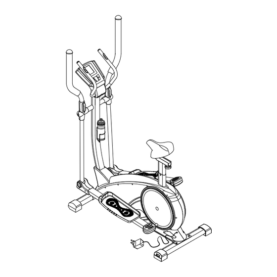
Page 5: Exploded Diagram
Exploded Diagram BRM 6110 Page 4... -
Page 6: Assembly Instructions
A s s e m b l y S t e p 1 Hardware Required Stabilizer Assembly Secure the Front Stabilizer (#2) and Rear Stabilizer (#3) to the Main Frame (#1) by using four Bolts (#35) and four Washers (#37). #66. Knob (M10) #63. Spring Loaded Knob BRM 6110 Page 5... - Page 7 Sensor Wire (lower) (#28a) to the Sensor Wire (middle) (#28b). C. Secure the Front Post (#4) to the Main Frame (#1) by using four Bolts (#39) and four Washers (#37). #66. Knob (M10) #63. Spring Loaded Knob BRM 6110 Page 6...
- Page 8 (#4) with no gap. Once you have confirmed that it is aligned properly, secure it with two Washers (#40), two Spring Washers (#42) 2 and two Hex Bolts (#41). #66. Knob (M10) #63. Spring Loaded Knob BRM 6110 Page 7...
- Page 9 (#60) and secure it with one Washer (#43) and one Nylon Nut (#45) as 2 shown in the assembly below. Repeat this process on the opposite side. 2 2 #66. Knob (M10) #63. Spring Loaded Knob BRM 6110 Page 8...
- Page 10 Left Pedal Arm (#9L) and the Left Lower Handlebar (#7L) can be properly aligned. Then slide the Left Lower Handlebar (#7L) into Left Pedal Arm (#9L). #66. Knob (M10) #63. Spring Loaded Knob BRM 6110 Page 9...
- Page 11 Assemble the End Caps (#18L-R & #18L-L) to the front of the Left Pedal Arm (#9L) with two Screws (#36). Repeat this process on the opposite side. #66. Knob (M10) #63. Spring Loaded Knob BRM 6110 Page 10...
- Page 12 To better fit the way you exercise you can customize the pedal to any of the 3 available positions that gives you most comfortable distance to grip the handlebars. 4 #66. Knob (M10) #63. Spring Loaded Knob BRM 6110 Page 11...
- Page 13 (#22L-1 & 22L-2) to the left Lower Handlebar (#7L). Align the two together and press firmly 4 until it snaps into place. Repeat this process on the opposite side. 4 #66. Knob (M10) #63. Spring Loaded Knob BRM 6110 Page 12...
- Page 14 A s s e m b l y S t e p 7 Hardware Required Middle Handlebar Assembly : Secure the Middle Handlebar (#5) to the Front Post (#4) by using two Spring Washers (#42) and two Bolts (#53). 2 2 #66. Knob (M10) #63. Spring Loaded Knob BRM 6110 Page 13...
- Page 15 Computer (#6). Attach the Cover of Handlebar (#25-1 & #25-2) to the Front Post (#4), and secure them with two Screws (#36) and one Screw (#55). #66. Knob (M10) #63. Spring Loaded Knob BRM 6110 Page 14...
- Page 16 Then secure the Water Bottle Holder (#56) to the 2 Front Post (#4) using the two Screws (#58) and two Washers (#59) that has just been removed. Slide the Water Bottle (#57) into place. 2 #66. Knob (M10) #63. Spring Loaded Knob BRM 6110 Page 15...
- Page 17 Do not remove the Seat (#70) for any reason after you have installed it. Exercising on this unit without the Seat (#70) can result in SERIOUS INJURY. Ensure the seat is locked in place by tightening the two knobs prior to use. BRM 6110 Page 16...
-
Page 18: Computer Operation
_<_ Fast Backwards and _>_ Fast Forward controls. _ON/OFF_: Exit Fig. 3 Note: The volume indicating slider will turn blue when the volume function is active. To access more functions please refer to the Mp4 Manual. Fig. 4 BRM 6110 Page 17... -
Page 19: Proof Of Purchase
Proof of purchase Model Number BRM 6110 version: - -2009 6 10 Page 18... - Page 20 Body Flex Sports, Inc. • 21717 Ferrero Parkway, Walnut, CA 91789 • Telephone: (888) 266 - 6789 • Email: info@bodyflexsports.com...
Need help?
Do you have a question about the BRM 6110 and is the answer not in the manual?
Questions and answers
How do you adjust the tension on the BRM 6110