Fluke 435-II Service Manual
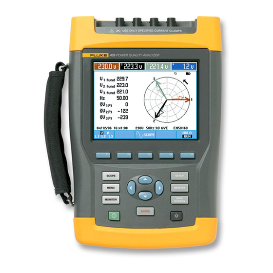
Three phase energy and power quality analyzer
Hide thumbs
Also See for 435-II:
- Technical data manual (9 pages) ,
- User manual (174 pages) ,
- Manual supplement (2 pages)
Table of Contents
Advertisement
Quick Links
Advertisement
Table of Contents

Subscribe to Our Youtube Channel
Related Manuals for Fluke 435-II


Summary of Contents for Fluke 435-II
-
Page 1: Service Manual
Advanced Test Equipment Rentals www.atecorp.com 800-404-ATEC (2832) Fluke 434-II/435-II/437-II Three Phase Energy and Power Quality Analyzer Service Manual PN 4822 872 05408 Febr. 2013 © 2013 Fluke Corporation, All rights reserved. All product names are trademarks of their respective companies. -
Page 3: Table Of Contents
Table of Contents Chapter Title Page Safety Instructions ..................1-1 1.1 Introduction....................1-3 1.2 Safety Precautions..................1-3 1.3 Caution and Warning Statements ..............1-3 1.4 Symbols .......................1-3 1.5 Impaired Safety....................1-4 1.6 General Safety Information .................1-4 1.7 Safe Handling and Use of Li-ion battery pack ..........1-4 Characteristics.................... - Page 4 Fluke 434-II/435-II/437-II Service Manual Calibration Adjustment................... 5-1 5.1 General......................5-3 5.1.1 Introduction ..................5-3 5.1.2 Calibration number and date ..............5-3 5.1.3 General instructions................5-3 5.1.4 Equipment required for calibration ............5-4 5.2 Calibration Procedure Steps.................5-4 5.3 Starting The Calibration................5-4 5.4 Contrast Calibration Adjustment ..............5-6 5.5 Warming Up ....................5-7...
-
Page 5: Safety Instructions
Chapter 1 Safety Instructions Title Page 1.1 Introduction....................1-3 1.2 Safety Precautions..................1-3 1.3 Caution and Warning Statements ..............1-3 1.4 Symbols .......................1-3 1.5 Impaired Safety....................1-4 1.6 General Safety Information .................1-4 1.7 Safe Handling and Use of Li-ion battery pack ..........1-4... -
Page 7: Introduction
Analyzer. See explanation in Users Manual DOUBLE INSULATION (Protection Class) Live voltage Earth Ground Static sensitive components Recycling information (black/yellow). Do no dispose of this product as Conformité Européenne unsorted municipal waste. Go to Fluke’s website for recycling information... -
Page 8: Impaired Safety
For instructions how to safely handle and use this battery pack refer to Chapter 1, General Aspects, Paragraph ‘Safe Use of Li-ion Battery Pack’ in the Users Manual of Fluke 434-II/435-II/437-II. The Users Manual can be downloaded from Fluke’s website. -
Page 9: Characteristics
Chapter 2 Characteristics Title Page 2.1 Introduction....................2-3... -
Page 11: Introduction
2.1 Introduction 2.1 Introduction Performance Characteristics For the specifications refer to the “Characteristics” Chapter 27 in the Fluke 434-II/435- II/437-II Users Manual. The Users Manual can be downloaded from Fluke’s website. Specifications are based on a one year calibration cycle. - Page 12 Fluke 434-II/435-II/437-II Service Manual...
-
Page 13: List Of Replaceable Parts
Chapter 3 List of Replaceable Parts Title Page 3.1 Introduction....................3-3 3.2 How to Obtain Parts..................3-3 3.3 Service Centers ....................3-3 3.4 Final Assembly Parts ...................3-4 3.5 Accessories ....................3-7... - Page 14 Fluke 434-II/435-II/437-II Service Manual...
-
Page 15: Introduction
List of Replaceable Parts 3.1 Introduction 3.1 Introduction This chapter contains an illustrated list of replaceable parts for the models 434-II, 435-II, and 437-II Power Quality Analyzer Series II. Parts are listed by assembly; alphabetized by item number or reference designator. Each assembly is accompanied by an illustration showing the location of each part and its item number or reference designator. -
Page 16: Final Assembly Parts
Fluke 434-II/435-II/437-II Service Manual 3.4 Final Assembly Parts See Table below. In Chapter 6 – Disassembling the Analyzer, pictures are present giving an impression on how the instrument is constructed. Dedicated pictues with item numbers are scheduled for a future revision of this Service Information. - Page 17 List of Replaceable Parts 3.4 Final Assembly Parts Part or Kit Ordering Code Consists of Following Parts Figure/Item nr Case) Side Strap 3945370 Can be fixed on Left or Right side Hang Strap 946769 Can be fixed op Top Side of Instrument Bottom Holster Set 4161646...
- Page 18 Fluke 434-II/435-II/437-II Service Manual Figure 3-1. Parts and kits 1. Figure 3-2. Parts and kits 2.
-
Page 19: Accessories
List of Replaceable Parts 3.5 Accessories 3.5 Accessories Refer to the Fluke 434-II/435-II/437-II Users Manual, Chapter 26 – Tips and Maintenance, for a list with standard and optional accessories. The Users Manual can be downloaded from the Fluke website. - Page 20 Fluke 434-II/435-II/437-II Service Manual...
-
Page 21: Performance Verification
Chapter 4 Performance Verification Title Page 4.1 Introduction....................4-3 4.2 Equipment Required for Verification ............4-4 4.3 Relation between Characteristics and Performance Test......4-4 4.4 General Instructions..................4-5 4.5 Operating Instructions..................4-5 Resetting the Analyzer ..................4-5 4.6 Display and Backlight Test................4-5 4.7. Verification of Current Inputs..............4-5 4.7.1 Preparation....................4-5 4.7.2 Accuracy....................4-6 4.7.3 Bandwidth check of current channels (*)..........4-7... - Page 22 Fluke 434-II/435-II/437-II Service Manual...
-
Page 23: Introduction
The Performance Verification Procedure is based on the specifications, listed in the “Characteristics” Chapter 26 in the Fluke 434-II/435-II/437-II Users Manual. The Users Manual can be downloaded from Fluke’s website. Specifications are based on a one year calibration cycle. The values given here are valid for ambient temperatures between 15 °C and 35 °C. -
Page 24: Equipment Required For Verification
4.2 Equipment Required for Verification The primary source instrument used in the verification procedures of Fluke 434-II/435- II/437-II is the Fluke 5700A. If not available, you can substitute another Calibrator as long as it meets the minimum test requirements. •... -
Page 25: General Instructions
Performance Verification 4.4 General Instructions 4.4 General Instructions Follow these general instructions for all tests: • It is recommended to remove the SD memory card from the Analyzer during the performance test to avoid that measuring data is written on it during the test. The SD card is located behind the battery door. -
Page 26: Accuracy
Fluke 434-II/435-II/437-II Service Manual Set Clamp for Phase and Neutral (select with F4) to 1 mV/A, 1000 A, x1, 1:1. To confirm press F5 – BACK. • Set the Analyzer in DEMO mode: press SETUP, press F1 - USER PREF, and select DEMO ON with F2. -
Page 27: Bandwidth Check Of Current Channels (*)
Performance Verification 4.7. Verification of Current Inputs SETUP 9. Press . Then press F4 – MANUAL SETUP and use arrow keys and ENTER key to set the Analyzer to Current Clamp sensitivity (Phase and Neutral: select with F4) to 1 mV/A, 100 A, x10 AC only, 1:1. 10. -
Page 28: Voltage Inputs
Fluke 434-II/435-II/437-II Service Manual Table 4-2. Bandwidth Check of Current Channels (x1, AC + DC) Current Channel to be verified Readout at 60 Hz (adjust Readout at 3 kHz Calibrator with EDIT FIELD) A/L1 1000 A 945 A or more... -
Page 29: Verification Of Voltage Inputs In 120 V Range
Performance Verification 4.8 Voltage Inputs CALIBRATOR NORMAL POWER ADAPTER BC 430 A/L1 B/L2 C/L3 ANALYZER A/L1 B/L2 C/L3 INPUT BLOCK Figure 4-2. Checking the A/L1, B/L2, and C/L3 voltage inputs 3. To check the N input, connect the N input with the adjacent C/L3 input. A/L1, B/L2, C/L3 now will give zero reading. - Page 30 3. Set the Calibrator to 60 Hz, 60 V and then to OPR. 4. Fluke 434-II: check for a voltage readout V rms between 59.4 ... 60.6 V. Fluke 435-II/437-II: check for a voltage readout V rms between 59.88 ... 60.12 V.
-
Page 31: Verification Of Voltage Inputs In 230 V Range
12. Set the Calibrator to 60 Hz / 60 V and then to OPR. 13. Fluke 434-II: check for a voltage readout V rms between 59.4 ... 60.6 V. Fluke 435-II/437-II: check for a voltage readout V rms between 59.88 ... 60.12 V. - Page 32 12. Set the Calibrator to 50 Hz / 115 V and then to OPR. 13. Fluke 434-II: check for a voltage readout V rms between 113.8 ... 116.2 V. Fluke 435-II/437-II: check for a voltage readout V rms between 114.77 ... 115.23 V.
-
Page 33: Verification Of Voltage Inputs In 400 V Range
3. Set the Calibrator to 50 Hz, 200 V and then to OPR. 4. Fluke 434-II: check for a voltage readout V rms between 198.0 ... 202.0 V. Fluke 435-II/437-II: check for a voltage readout V rms between 199.60 ... 200.40 V. - Page 34 12. Set the Calibrator to 50 Hz / 200 V and then to OPR. 13. Fluke 434-II: check for a voltage readout V rms between 198.0 ... 202.0 V. Fluke 435-II/437-II: check for a voltage readout V rms between 199.60 ... 200.40 V.
-
Page 35: Verification Of Voltage Inputs In 6 Kv Range (Transients)
18. Increase the frequency to 3 kHz. Fluke 434-II: Check for a readout of 204.2 V or more. Fluke 435-II/437-II: Check for a readout of 204.25 V or more. 19. Set the Calibrator to STBY. 4.8.5 Verification of voltage inputs in 6 kV range (Transients) Note: this test is not required for Fluke 434-II. - Page 36 (AMPL/FREQ key) to adjust the Calibrator to an Analyzer readout of 215 V. 8. Increase the frequency to 3 kHz. Fluke 435-II/437-II: check for a readout of 204.2 V or more. Check the channels according to the table below. Table 4-13. Bandwidth Check of Voltage Channels A/L1, B/L2, C/L3...
-
Page 37: Channel Isolation (*)
4.9 Channel Isolation (*) 17. Increase the frequency to 3 kHz. Fluke 435-II/437-II: check for a readout of 204.2 V or more. 18. Set the Calibrator to STBY. Note: bandwidth will be slightly higher than in V/A/Hz mode because a low pass filter in the analog input channel is off during Transients mode. - Page 38 Fluke 434-II/435-II/437-II Service Manual CALIBRATOR NORMAL POWER ADAPTER BC 430 A/L1 B/L2 C/L3 ANALYZER A/L1 B/L2 C/L3 INPUT BLOCK 50 OHM 50 OHM 50 OHM 50 OHM PIECE PIECE PIECE PIECE Figure 4-4. Checking the Channel isolation. 4-18...
-
Page 39: Calibration Adjustment
Chapter 5 Calibration Adjustment Title Page 5.1 General......................5-3 5.1.1 Introduction ..................5-3 5.1.2 Calibration number and date ..............5-3 5.1.3 General instructions................5-3 5.1.4 Equipment required for calibration ............5-4 5.2 Calibration Procedure Steps.................5-4 5.3 Starting The Calibration................5-4 5.4 Contrast Calibration Adjustment ..............5-6 5.5 Warming Up ....................5-7 5.6 Final Calibration ..................5-8 5.6.1 Warming Up Final................5-8 5.6.2 Offset adjustment .................5-8... -
Page 41: General
5.1.1 Introduction The following information, provides the complete Calibration Adjustment procedure for the Fluke 434-II/435-II/437-II Energy & Power Quality Analyzer (referred to as Analyzer). The Analyzer allows closed-case calibration using known reference sources. It measures the reference signals, calculates the correction factors, and stores the correction factors in RAM. -
Page 42: Equipment Required For Calibration
The primary source instrument used in the calibration procedures for Fluke 434-II/435- II/437-II (Series II) is the Fluke 5700A Calibrator. If the required type is not available, you can substitute another Calibrator as long as it meets the minimum test requirements. - Page 43 Calibration Adjustment 5.3 Starting The Calibration • Operate to adjust each selected item Year, Month, and Day. • Press to leave the SETUP DATE menu. 4. Select the calibration mode. The Calibration Adjustment Procedure uses built-in calibration setups, that can be accessed in the calibration mode.
-
Page 44: Contrast Calibration Adjustment
Fluke 434-II/435-II/437-II Service Manual Functions of the keys F1-F4 are: select the previous step PREV select the next step NEXT start the calibration adjustment of the actual step leave the calibration mode EXIT 5.4 Contrast Calibration Adjustment After entering the calibration mode the display shows:... -
Page 45: Warming Up
Calibration Adjustment 5.5 Warming Up Figure 5-2. Version & Calibration data. 5.5 Warming Up The Warming Up state will be entered after entering the calibration mode (section 5.3), or after selecting the next step if you have done the Contrast Calibration step CL 120 (section 5.4). -
Page 46: Final Calibration
Fluke 434-II/435-II/437-II Service Manual 5.6 Final Calibration Before starting the final calibration you must have done the Warming Up (section 5.5)! The final calibration is simple and straightforward and consists of the following elements: - Offset adjustment of voltage and current inputs (0 V input signal). - Page 47 Calibration Adjustment 5.6 Final Calibration CALIBRATOR NORMAL POWER ADAPTER BC 430 A/L1 B/L2 C/L3 PM 9093 PM 9093 PM 9093 ANALYZER A/L1 B/L2 C/L3 INPUT BLOCK PM 9082 PM 9092 Figure 5-3. Offset, Low Voltage, and Current Gain Adjustment 2. The display must show step CL 0300. If it does not, then press to select the first calibration step in Table 5- 3.
-
Page 48: Low Voltage And Current Gain Adjustment
Fluke 434-II/435-II/437-II Service Manual Table 5-1. Offset Adjustment of all Inputs Cal step Description Calibrator Setting CL 0300 OffsetLowVolt 0 V, 0 Hz, OPR CL 0310 Offset125Volt 0 V, 0 Hz, OPR CL 0320 Offset250Volt 0 V, 0 Hz, OPR... - Page 49 Calibration Adjustment 5.6 Final Calibration CALIBRATOR NORMAL POWER ADAPTER BC 430 A/L1 B/L2 C/L3 ANALYZER A/L1 B/L2 C/L3 INPUT BLOCK Figure 5-4. Voltage Gain Adjustment 3. Set the Calibrator to supply 120 V, 50 Hz. Warning Dangerous voltages will be present on the calibration source and connection cables during the following steps.
-
Page 50: Save Calibration Data And Exit
Fluke 434-II/435-II/437-II Service Manual Table 5-2. Voltage Gain Adjustment Cal step Description Calibrator Setting CL 0410 Gain125Volt 120 V, 50 Hz, OPR CL 0420 Gain250Volt 230 V, 50 Hz, OPR CL 0430 Gain500Volt 480 V, 50 Hz, OPR CL 0440... - Page 51 Calibration Adjustment 5.7 Save Calibration Data And Exit Proceed as follows: • If you did the Warming Up and Pre-Calibration successfully (section 5.5), and you want to store the Pre-Calibration data before continuing with the Final Calibration: ⇒ Press When turning the Analyzer off and on again, it will show the message: The instrument needs calibration.
- Page 52 Fluke 434-II/435-II/437-II Service Manual 5-14...
-
Page 53: Disassembling The Analyzer
Chapter 6 Disassembling the Analyzer Title Page 6.1. Introduction....................6-3 6.2. Disassembly & Reassembly Procedures.............6-3 6.2.1 Required Tools ..................6-3 6.2.2 Removing the Tilt Stand, Hang Strap, and Side Strap ......6-3 6.2.3 Opening the Analyzer, Removing the Battery Pack......6-4 6.2.4 Getting access to Top Side of PCA ............6-5 6.2.5 Getting access to Bottom Side of PCA..........6-5 6.2.6 Getting access to LCD, Keypad Foil and Keypad........6-5 6.2.7 Pictures Showing Disassembly Steps...........6-6... -
Page 55: Introduction
The Analyzer contains static sensitive components. Handling and servicing these components should be done only at a static free workstation by qualified personnel. The Analyzer contains a Li-ion battery pack. Refer to the Fluke 434-II/435-II/437-II (Series II ) Users Manual ‘Safety Information’ Chapter (page 1-7 onwards) for instructions how to safely handle and use this battery pack. -
Page 56: Opening The Analyzer, Removing The Battery Pack
Fluke 434-II/435-II/437-II Service Manual Before opening the Analyzer, you must remove the Hang Strap and the Side Strap. How to remove and install the Hang Strap is explained in the Users Manual in Chapter 4. The grip of the Side Strap consists of two halves kept together with Velcro tape. After having opened it, the straps can be taken apart and be removed from their fixing dowels in the side of the Analyzer. -
Page 57: Getting Access To Top Side Of Pca
Disassembling the Analyzer 6.2. Disassembly & Reassembly Procedures keyboard and wiring of battery door detection are not damaged inbetween case parts. 6.2.4 Getting access to Top Side of PCA During disassembly, take careful notice of the position of isolation foils in so that you are able to install them in their original position. -
Page 58: Pictures Showing Disassembly Steps
Fluke 434-II/435-II/437-II Service Manual 4. Remove the remaining 2 selftapping screws 8.5 mm long (total length) that fix the Main PCA module to the top case assembly. The screws are located at the bottom side of the keyboard. 5. Separate the Main PCA module from the top case. - Page 59 Disassembling the Analyzer 6.2. Disassembly & Reassembly Procedures Fig. 6-2. Dismantling step 2 (Top side of PCA attainable) Fig. 6-3. Dismantling step 3 (PCA separated from chassis)
- Page 60 Fluke 434-II/435-II/437-II Service Manual Fig. 6-3. Dismantling step 4 (Main PCA Module separated from front case) Fig. 6-5. Dismantling step 5 (Main PCA Module separated from front case, keypad foil removed)
Need help?
Do you have a question about the 435-II and is the answer not in the manual?
Questions and answers