
Related Manuals for Fluke 438-II


Summary of Contents for Fluke 438-II
- Page 1 438-II Motor Analyzer Users Manual March 2016 Rev. 1, 10/17 ©2016-2017 Fluke Corporation. All rights reserved. All product names are trademarks of their respective companies.
- Page 2 LIMITED WARRANTY AND LIMITATION OF LIABILITY Each Fluke product is warranted to be free from defects in material and workmanship under normal use and service. The warranty period is three years and begins on the date of shipment. Parts, product repairs, and services are warranted for 90 days.
-
Page 3: Table Of Contents
How to Contact Fluke ........ - Page 4 438-II Users Manual...
-
Page 5: Introduction
(VSD). It is a standard feature on the Fluke 438-II and available as an optional upgrade for all models in the Fluke 430 Series II (Fluke 430-II/MA Motor Analyzer upgrade). Combined with electrical power and power-quality measurements, the Motor Analyzer feature provides useful information about a motor’s mechanical and... -
Page 6: Safety Information
USB Interface Cable for PC Connection (USB A-to-mini USB B) • Soft Carry Case C1740 Additional kits are available that include Flexible 6000 A AC Current Probes (set of 4). Contact Fluke for more information about the kits that are available for the Motor Analyzer. -
Page 7: Motor Measurements
WYE or Delta Table 2 is a list of the range and accuracy of the Motor Analyzer-specific functions. See Specifications in the Fluke 430 Series II Users Manual for the specifications of the other functions. Table 2. Motor Analyzer Range and Accuracy... -
Page 8: Motor Setup
438-II Users Manual Motor Setup The motor nameplate provides information for the measurement algorithm. This information determines the mechanical parameters from the electrical signals that are used for measurements. It is critical that you enter the nameplate settings accurately to obtain accurate readings. - Page 9 Motor Analyzer Motor Setup Table 5. Motor Design Type and Characteristics Summary Motor Design NEMA-A NEMA-B NEMA-C NEMA-D NEMA-E IEC-H IEC-N Starting Current High Medium Medium Medium Medium Medium Medium Starting Torque Medium Medium High Very High Medium High Medium Breakdown Torque High Medium...
-
Page 10: Unit Setup
438-II Users Manual See Table 7 for a list of the supported VSDs. Table 7. Supported Variable Speed Drives Drive Characteristics Supported Range Drive Output Frequency 41 Hz to 69 Hz Drive Type Voltage Source Inverter only V/f (Volt over Hertz) only, open loop vector control, closed loop... -
Page 11: Set Analyzer Limits
Motor Analyzer Motor Setup Set Analyzer Limits You can adjust the default limit values that show the system performance in various bar graphs. The limits you enter here adjust where the bar graph shows the transition from orange to red. See Motor Analyzer Parameters on page 8 for more information. -
Page 12: Motor Analyzer Parameters
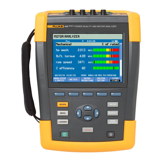
438-II Users Manual Motor Analyzer Parameters The MOTOR ANALYZER screen shows the important mechanical and electrical parameters relative to their rated values, industry standards, or the NEMA MG 1-2014 standard. A separate screen is available for the Mechanical Parameters and one for the Electrical Parameters. -
Page 13: Electrical Parameters
Motor Analyzer Motor Analyzer Parameters Electrical Parameters The second screen is the electrical power and power factor. It shows the voltage unbalance and harmonics voltage factor according to NEMA MG1. to move between the screens for electrical and mechanical parameters. Softkeys: View ANALYZER LIMITS screen. -
Page 14: Meter Screen
438-II Users Manual Meter Screen The METER screen shows all measurements in the Motor Analyzer mode as a table view. Available readings: Motor Power (k)W or hp Torque Nm or lb.ft Note To select between kW or hp and Nm or lb.ft in, see Unit Setup on page 6. -
Page 15: Trend
Motor Analyzer Motor Analyzer Parameters Softkeys: to scroll through the METER screen. Opens the ANALYZER screen. Opens the TREND screen. Opens the MOTOR SETUP screen. STOP measurements and save measurement results. Trend The Trend screen is the standard trend function from the 43X-Series II that shows the recorded measurement data over time. -
Page 16: Derating Screen
438-II Users Manual Derating Screen NEMA has guidelines for the application of induction motors to the characteristics of the power system. The NEMA standard MG 1 2014 recommends derating the permissible motor load if Voltage Unbalance or Voltage Harmonics exist in the power system. -
Page 17: Voltage Harmonics
Motor Analyzer Motor Analyzer Parameters Voltage Harmonics Harmonic currents are introduced when the line voltages applied to the motor include voltage components at frequencies other than the fundamental frequency of the supply (50 Hz or 60 Hz). The temperature of the motor operating at a particular load and per unit voltage harmonic factor will therefore be greater than that for the motor operating under the same conditions with only voltage at the fundamental frequency applied. - Page 18 438-II Users Manual The actual load and derating factor is indicated with a cross-hair. The green area indicates a motor that operates within rated limits. The yellow area indicates the permissible Service Factor area (the Service Factor is from the nameplate on the motor and entered in the Motor Setup screen). The red area indicates the overload area for the motor.
Need help?
Do you have a question about the 438-II and is the answer not in the manual?
Questions and answers