Table of Contents
Advertisement
Rating:
Amperes:
Blade speed:
Blade:
Wood maximum cutting depth:
Steel maximum thickness:
Bevel angle:
Weight:
Need Assistance?
Call us on our toll free customer support line:
1-800-689-9928
Technical questions
Replacement parts
Parts missing from package
Imported by Mastercraft Canada Toronto, Canada M4S 2B8
PRODUCT SPECIFICATIONS
120 V, 60 Hz AC
13 A
4800 RPM (no load)
7 ¼" (18.4 cm), 5/8" (15.9 mm) arbour,
40 Tungsten carbide teeth
2 ½" (64 mm) @ 90°
1 13/16" (46 mm) @ 45°
1/8" (3.2 mm)
0–50°
13 lb 14 oz (6.3 kg)
EASY SAW
054-8326-0
Owner's Manual
Advertisement
Table of Contents

Related Manuals for MasterCraft 054-8326-0


Summary of Contents for MasterCraft 054-8326-0
-
Page 1: Product Specifications
Bevel angle: 0–50° Weight: 13 lb 14 oz (6.3 kg) Need Assistance? Call us on our toll free customer support line: 1-800-689-9928 Technical questions Replacement parts Parts missing from package Imported by Mastercraft Canada Toronto, Canada M4S 2B8... -
Page 2: Table Of Contents
TABLE OF CONTENTS Product specifications ………….……………………………………………………. Table of contents ……………………………………………………………………... General safety warnings …………………………………………………………….. 3–4 Eye, ear & lung protection …………………………………………………………… 3–4 Electrical safety ………………………………………………………………………. Power tool safety ……………………………………………………………………... 5–6 General safety rules ………………………………………………………………….. Work area ………………………………………………………………….………….. Electrical safety ………………………………………………………………………. Personal safety ……………………………………………………………………….. -
Page 3: General Safety Warnings
GENERAL SAFETY WARNINGS WARNING: Before using this tool or any of its accessories, read this manual and follow all Safety Rules and Operating Instructions. The important precautions, safeguards and instructions appearing in this manual are not meant to cover all possible situations. It must be understood that common sense and caution are factors which cannot be built into the product. -
Page 4: Electrical Safety
GENERAL SAFETY WARNINGS WEAR A DUST MASK THAT IS DESIGNED TO BE USED WHEN OPERATING A POWER TOOL IN A DUSTY ENVIRONMENT. WARNING: Dust that is created by power sanding, sawing, grinding, drilling, and other construction activities may contain chemicals that are known to cause cancer, birth defects, or other genetic abnormalities. -
Page 5: Power Tool Safety
POWER TOOL SAFETY WARNING Read all safety warnings Damaged or entangled cords increase the and instructions. Failure to follow the risk of electric shock. warnings and instructions may result in electric shock, fire and/or serious injury. When operating a power tool outdoors, use an extension cord suitable for Save all warnings and instructions for outdoor use. -
Page 6: Use And Care Of Power Tools
POWER TOOL SAFETY PERSONAL SAFETY – cont’d Maintain power tools. Check for misalignment or binding of moving Do not overreach. Keep proper footing parts, breakage of parts and any other and balance at all times. This enables condition that may affect the power tool’s operation. -
Page 7: Specific Safety Rules
SPECIFIC SAFETY RULES Adjust the cutting depth according to WARNING: Know your circular the thickness of the workpiece. Less saw. Do not plug the tool into the power than a full tooth of the blade teeth should source until you have read and be visible below the workpiece or understand this Instruction Manual. - Page 8 SPECIFIC SAFETY RULES CAUSES AND OPERATOR When restarting a saw in the workpiece, PREVENTION OF KICKBACK centre the saw blade in the kerf and check that saw teeth are not engaged Kickback is a sudden reaction to a into the material. If the saw blades are pinched, bound or misaligned saw blade, binding, it may walk up or kickback from causing an uncontrolled saw to lift up and...
-
Page 9: Specific Safety Rules
SPECIFIC SAFETY RULES ADDITIONAL SPECIFIC SAFETY RULES – DANGER: To avoid injury from cont’d accidental starting, always remove the plug from the power source before The lower guard should be retracted making any adjustments and before manually only for special cuts such as installing or removing a saw blade. -
Page 10: Extension Cord Safety
EXTENSION CORD SAFETY WARNING: Keep the extension MINIMUM GAUGE (AWG) cord clear of the working area. Position EXTENSION CORDS (120 V use only) the cord so it will not get caught on the Amperage workpiece, tools or any other obstructions rating Total length while you are working with the power tool. -
Page 11: Symbols
SYMBOLS WARNING: Some of the following symbols may appear on the easy saw. Study these symbols and learn their meaning. Proper interpretation of these symbols will allow for more efficient and safer operation of this tool. Direct current Volts Amperes No load speed Alternating or direct Hertz... -
Page 12: Know Your Easy Saw
KNOW YOUR EASY SAW ON/OFF Main handle Trigger switch Laser ON/OFF button Lock-off button Depth adjustment Front handle stop button Vacuum port baffle Brush cap Laser adjustment screw Vacuum port Rip guide adjustment knob Bevel cutting adjustment lever Blade guard lever 45°... -
Page 13: Accessories
CONTENTS ACCESSORIES AVAILABLE ACCESSORIES CONTENTS Carefully unpack the easy saw. Compare WARNING: Use only accessories the contents against the “EASY SAW that are recommended for this easy COMPONENTS” and “GUIDE TRACK saw. Follow the instructions that COMPONENTS” charts below. accompany the accessories. The use of NOTE: See illustrations of the easy saw improper accessories may result in components on Pages 14 &... - Page 14 CONTENTS...
- Page 15 CONTENTS...
-
Page 16: Assembly And Operating
ASSEMBLY AND OPERATING INSTALLING THE TRACK RIDER Slide the lower locking tabs (2) upward into the matching slots (3) in The track rider is required for use with the the upper blade guard (Fig. 3). guide track. It is recommended that the track rider be installed on the easy saw and left in place during general cutting. -
Page 17: Changing The Blade
ASSEMBLY AND OPERATING ASSEMBLY AND OPERATING INSTALLING THE METAL CUTTING SHIELD – cont’d Rotate the locking cam arm (4) counter clockwise and push the locking cam into the matching hole (5) in the upper blade guard. Rotate the locking cam arm clockwise to lock the shield into place. - Page 18 ASSEMBLY AND OPERATING ASSEMBLY AND OPERATING CHANGING THE BLADE – cont’d While holding the blade guard lever in the open position, lift the blade off the shaft (8) and slide it out through the slot in the sole plate (9). NOTE: Do NOT remove the inner large flange washer.
-
Page 19: Setting The Cutting Depth
ASSEMBLY AND OPERATING SETTING THE CUTTING DEPTH The cutting depth of the blade should be set to suit the thickness of the material being cut. The cutting depth should be approximately 1/8" (3 mm) greater than the thickness of the material being cut. WARNING: The cutting depth adjusting system is spring loaded. -
Page 20: Installing The Rip Guide
ASSEMBLY AND OPERATING BEVEL CUTTING ANGLE– cont’d Adjusting the sole plate angle Loosen the bevel adjustment by lifting upward on the bevel gauge adjustment lever (1) (Fig. 8). Rotate the sole plate (2) to the desired angle as shown on the bevel gauge (3). - Page 21 ASSEMBLY AND OPERATING VACUUM PORT – cont’d NOTE: When cutting wood without using the workshop vacuum, the vacuum port baffle should be closed to limit the amount of sawdust being exhausted toward the operator. WARNING: The vacuum port baffle MUST be in the closed position when cutting metal to prevent hot cuttings from hitting the operator.
-
Page 22: Lock-Off Button
ASSEMBLY AND OPERATING LOCK-OFF BUTTON The lock-off button (1) is a safety device designed to reduce the possibility of accidentally starting the saw (Fig. 11). This button must be depressed before the trigger switch (2) can be depressed. NOTE: The lock-off button can be depressed either left or right. -
Page 23: Laser Adjustment
ASSEMBLY AND OPERATING LASER ADJUSTMENT The laser guide line should be centered in the 0° cutting groove (1) (Fig. 13). If the laser guide line is not correctly centered it can be centered using a 5/64” (2 mm) slot screwdriver. Moving the laser line to the right Turn the right laser adjustment screw (2) counter clockwise ¼... -
Page 24: Materials You Can Cut
ASSEMBLY AND OPERATING MATERIALS YOU CAN CUT The easy saw is a versatile saw that allows you to cut many different types of materials. Some of the materials include: ● Wood products such as lumber, hardwood, plywood, composition board and panelling ●... - Page 25 ASSEMBLY AND OPERATING GENERAL CUTTING – cont’d DANGER: Any workpiece that is not adequately clamped in place or properly supported for cutting may come loose or jamb the blade, causing serious injury. Never hold the workpiece in your hand. Make sure there are no nails, screws, clamps or foreign materials in the path of the saw blade.
-
Page 26: Plunge Cutting
ASSEMBLY AND OPERATING PLUNGE CUTTING WARNING: To avoid loss of control, damage to the blade or damage to the workpiece, always use extreme caution when making plunge cuts. It is not recommended to plunge cut any material other than wood. To plunge cut inside the edges of a workpiece, clearly mark the cutting line on the workpiece. -
Page 27: Metal Cutting
ASSEMBLY AND OPERATING METAL CUTTING Several types of metal can be cut with your easy saw. NOTES: Use only the 40 tooth blade supplied with the tool to cut metal Only cut aluminum, copper and steel Do NOT attempt to cut metals thicker than 1/8”... -
Page 28: Assembling The Guide Track
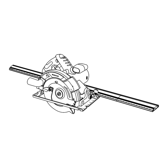
ASSEMBLY AND OPERATING ASSEMBLING THE GUIDE TRACK The aluminum guide track is used in conjunction with the easy saw to make precise cuts across a workpiece up to 39” (1 m) wide. The guide track is shipped in four sections. To assemble the guide track, you will need a table or work bench at least 4’... -
Page 29: Assembling The Guide Track
ASSEMBLY AND OPERATING ASSEMBLING THE GUIDE TRACK – cont’d Lay the third track section marked “C” (6) on its back (Fig. 23). Slide the cavities over the two joining bars that are protruding from the right hand end of track section “B” and fasten in place using two screws (4). -
Page 30: Cutting Using The Guide Track
ASSEMBLY AND OPERATING CUTTING USING THE GUIDE TRACK The guide track can be used to make precision cuts on workpieces up to 39” (1 m) wide. Install the track rider on the sole plate (Fig. 1). Mark the cut line (1) on the workpiece (Fig. -
Page 31: Installing Zero Clearance Inserts
ASSEMBLY AND OPERATING CUTTING USING THE GUIDE TRACK – cont’d Place one small clamp on the left hand side of the guide track at each end to hold it firmly onto the workpiece with the right edge on the guide track alignment marks. - Page 32 ASSEMBLY AND OPERATING INSTALLING ZERO CLEARANCE INSERTS – cont’d To install a zero clearance insert: Release the depth adjustment lever to allow the sole plate to completely clear the saw blade. Place the insert tabs (1) into the four slots (2) in the under side of the sole plate (3) (Fig.
-
Page 33: Maintenance
MAINTENANCE REPLACING THE CARBON MOTOR BRUSHES The carbon motor brushes will wear down and require replacing. The time intervals between replacements will vary depending upon the torques being achieved and the hours of use. It is recommended that the brushes be checked after each 10 hours of use. -
Page 34: General Maintenance
MAINTENANCE GENERAL It has been found that electric tools are subjected to accelerated wear and WARNING: When servicing this possible premature failure when they are tool, use only identical replacement used on fibreglass boats and sports cars, parts. The use of any other part may wallboard, spackling compounds or create a hazard or cause product plaster. -
Page 35: Exploded View
EXPLODED VIEW... -
Page 36: Exploded View
EXPLODED VIEW – GUIDE TRACK... -
Page 37: Parts List
PARTS LIST ® WARNING: When servicing, use only Mastercraft replacement parts. The use of any other parts may create a safety hazard or cause damage to the easy saw. Any attempt to repair or replace electrical parts on this easy saw may create a safety hazard unless repairs are performed by a qualified technician. - Page 38 PARTS LIST Key # Part # Part Name Quantity 3140040012 629 bearing cover 3150060030 Plastic brush support 2030070010 Copper brush sleeve 1230010076 Carbon brush 3150140019 Carbon brush cover 4030010099 Tapping screw 4X14 2030050002 Cable clamp 3140010006 Cable guard 1190030031 Cable 4010010084 629 2RS bearing 1010120007...
- Page 39 PARTS LIST Key # Part # Part Name Quantity 4020010003 Screw M4x12 (black) 2030020163 Flat washer 4x11 (black) 2050060141 Moveable guard tortional spring 3120100038 Tortional spring stop 4020010103 Screw M3x8 (black) 3180040097 Vacuum dust port 3140070017 Vacuum dust port baffle cover 3180040098 Vacuum dust port baffle 4020010019...
- Page 40 PARTS LIST – GUIDE TRACK Key # Part # Part Name Quantity 2020210006 Track section "A" 2020210007 Track section "B" 2020210008 Track section "C" 2020210009 Track section "D" 2040160132 Joining Rod 4020020001 Screw 3160090066 Track end cap...
-
Page 41: 3-Year Limited Warranty
3-Year Limited Warranty This Mastercraft product is guaranteed for a period of 3 years from the date of original retail purchase against defects in workmanship and materials, except for the following components: Component A: Batteries, chargers and carrying cases, which are guaranteed for a period of 2 years from the date of original retail purchase against defects in workmanship and materials;... - Page 42 Mastercraft is a superior line of products selected for their workmanship and materials. These products are designed to meet rigorous quality and performance standards, and are approved by our Quality Assurance laboratory.
Need help?
Do you have a question about the 054-8326-0 and is the answer not in the manual?
Questions and answers
I purchased the Mastercraft Easy Saw many years ago. It’s a great saw but quite large and heavy so have not used it much. Only for bigger jobs. For the first time I decided to try the guide track that came with it, only to find that the 6 joining bars and the 12 screws that were supposed to be included, were never in the box. I know I am at fault for never checking to ensure all the contents were there, likely because it was some time before I ever opened the box for the first time. My question is, are these parts still available and what would they cost? I live in Timmins, Ontario.