
Subscribe to Our Youtube Channel
Related Manuals for MasterCraft 054-7595-4


Summary of Contents for MasterCraft 054-7595-4
- Page 1 8 1/4”(210 mm) 2 x 20V MAX* TABLE SAW KIT IMPORTANT: INSTRUCTION Please read this manual carefully before using this MANUAL table saw and save it for reference. model no. 054-7595-4...
-
Page 3: Specifications
054-7595-4 | contact us 1-800-689-9928 GENERAL POWER TOOL SAFETY WARNINGS SPECIFICATIONS Save all warnings and instructions for future reference. The term “power tool” in the warnings refers to your mains-operated (corded) power tool or battery- MOTOR 40 V operated (cordless) power tool. - Page 4 054-7595-4 | contact us 1-800-689-9928 as dust mask, non-skid safety shoes, hard hat, or hearing protection used for appropriate conditions • Keep handles and grasping surfaces dry, clean and free from oil and grease. Slippery will reduce personal injuries.
-
Page 5: Safety Instructions For Table Saws
054-7595-4 | contact us 1-800-689-9928 SAFETY INSTRUCTIONS FOR TABLE SAWS • Use only the push stick provided by the manufacturer or constructed in accordance with the instructions. This push stick provides sufficient distance of the hand from the saw blade. -
Page 6: Additional Safety Rules For Table Saws
054-7595-4 | contact us 1-800-689-9928 • Align the fence to be parallel with the saw blade. A misaligned fence will pinch the workpiece holes. Saw blades that do not match the mounting hardware of the saw will run off-centre causing against the saw blade and create kickback. - Page 7 054-7595-4 | contact us 1-800-689-9928 • Never cut metals, cement board, or masonry. These materials need to be cut by SAFETY RULES FOR BATTERY AND CHARGER other special tools. Cutting them with this tool can result in damage to the saw and •...
- Page 8 054-7595-4 | contact us 1-800-689-9928 reassembly may result in a risk of electric shock, electrocution or fire. SYMBOL • To prevent the risk of electric shock, unplug the charger from the outlet before attempting Some of the following symbols may be used on this product. Please study them and learn their meaning.
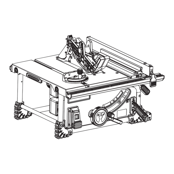
- Page 9 054-7595-4 | contact us 1-800-689-9928 Description Description Blade guard Push stick Riving knife Rip fence Anti-kickback pawls Scale Main table Extension table lock lever Right extension table Mitre gauge storage Table insert Rip-fence storage Mitre gauge Anti-kickback pawls storage...
- Page 10 054-7595-4 | contact us 1-800-689-9928 Blade guard: The guard is installed over the riving knife. It protects the operator’s hand from being cut PACKAGE CONTENTS FOR TABLE SAW while providing a clear view of the material to be cut during through-sawing cuts.
- Page 11 054-7595-4 | contact us 1-800-689-9928 • Remove the rechargeable battery from the tool. HEIGHT/BEVEL ADJUSTING HANDWHEEL (Fig. 1) • Remove the table insert. • To adjust the height of the saw blade, turn the • Using the hand wheel set the blade to max. cutting height-adjusting knob (1) clockwise to raise the depth, move to 0°...
-
Page 12: Remove The Blade
054-7595-4 | contact us 1-800-689-9928 mounting fork (1) is parallel to the table. • With the guard device assembled, set the blade to the maximum height. • Release the guard-release lever (2) until you see it goes back into the locking position. Check that •... -
Page 13: Install The Blade
054-7595-4 | contact us 1-800-689-9928 • Using the blade wrench A, place it on the blade bolt (2). RIP FENCE INSTALLATION AND USE (Fig. 8) • Holding both wrenches firmly, pull the blade wrench A toward to you. (Loosen the bolt counter- INSTALLATION: clockwise with the wrench A.) - Page 14 054-7595-4 | contact us 1-800-689-9928 • If the two measurements are not the same, loosen the two bolts (4) on the rip fence and then align it. • Using the main scale (1), adjust the rip fence (3) to the 10”...
- Page 15 054-7595-4 | contact us 1-800-689-9928 • Raise blade by turning height-adjusting knob • With the blade (3) set at 90°, slowly turn the 90°- (3) on the height/bevel adjusting handwheel stop set screw (2) until you feel resistance. Bevel (2) clockwise.
- Page 16 054-7595-4 | contact us 1-800-689-9928 PUSH STICK STORAGE: (Fig. 20) BLADE GUARD STORAGE: (Fig. 22) When not in use, insert the push stick through the When not in use, the blade guard can be stored under the table. Lock the blade guard into place in the same push stick holder (1).
-
Page 17: Causes Of Kickback
054-7595-4 | contact us 1-800-689-9928 APPLICATION • Always use a clean, sharp, and properly set blade. Never make cuts with a dull blade. Never use a warped saw blade or saw blade with cracked or broken teeth. Sharp and properly set saw blades Use the table saw for the purposes listed below: minimize binding, stalling and kickback. -
Page 18: Installing And Removing The Battery
054-7595-4 | contact us 1-800-689-9928 • Clean the saw, blade guard, under the table insert, and any areas where saw dust or scrap HOW TO MAKE A PUSH BLOCK workpieces may gather. Push blocks are blocks used to securely hold down the workpiece against the table. They include some •... -
Page 19: Making A Bevel Rip Cut
054-7595-4 | contact us 1-800-689-9928 MAKING CUTS a narrow piece, attach the auxiliary fence assembly to rip fence, use push stick and/or push blocks to move piece through cut and past blade. MAKING A RIP CUT (Fig. 27) •... - Page 20 054-7595-4 | contact us 1-800-689-9928 • To turn saw on, press the green button on the on/off switch. • Hold the workpiece firmly when feeding the workpiece into the blade. • Let the blade build up to full speed before moving the workpiece into the blade.
- Page 21 054-7595-4 | contact us 1-800-689-9928 GENERAL MAINTENANCE • Exterior may be cleaned with a cloth or soft non-metallic brush. Battery pack removal and preparation for recycling Avoid using solvents when cleaning plastic parts. Most plastics are susceptible to damage from various types of commercial solvents and may be damaged by their use.
- Page 22 054-7595-4 | contact us 1-800-689-9928 PROBLEM POSSIBLE CAUSES SOLUTION Install the battery. Refer to INSTALLING Battery not installed. AND REMOVING BATTERY PACK. Saw will not start Battery not charged. Charge battery. Blade does not come Low voltage of battery.
- Page 23 054-7595-4 | contact us 1-800-689-9928...
- Page 24 054-7595-4 | contact us 1-800-689-9928...
- Page 25 Description Qty. When servicing the Mastercraft 8 1/4” (21 CM) 2 x 20 V Max* table saw, use only Mastercraft ® ® replacement parts. The use of any other parts may cause damage to the product. All servicing of the table...
-
Page 26: Base Assembly
054-7595-4 | contact us 1-800-689-9928 Bracket & motor assembly Base assembly Description Qty. Description Qty. Description Qty. Description Qty. Butterfly nut 2-31 Flat key Screw 3-17 Screw Wrench A 2-32 Big gear Washer 3-18 Left foot pad cover (front) -
Page 27: Guard Assembly
054-7595-4 | contact us 1-800-689-9928 Table insert Description Qty. Description Qty. Description Qty. Description Qty. 4-23 Gasket 4-28 Clamp piece 4-24 Flat washer 4-29 Self-tapping screw Self-tapping screw O-ring 4-25 Spring 4-30 Butterfly nut Flat washer Lock knob... -
Page 28: Year Limited Warranty
This warranty applies only to the original purchaser and may not be transferred. Neither the retailer nor This Mastercraft product is guaranteed for a period of 3 years from the date of original retail purchase the manufacturer shall be liable for any other expense, loss or damage, including, without limitation,...
Need help?
Do you have a question about the 054-7595-4 and is the answer not in the manual?
Questions and answers