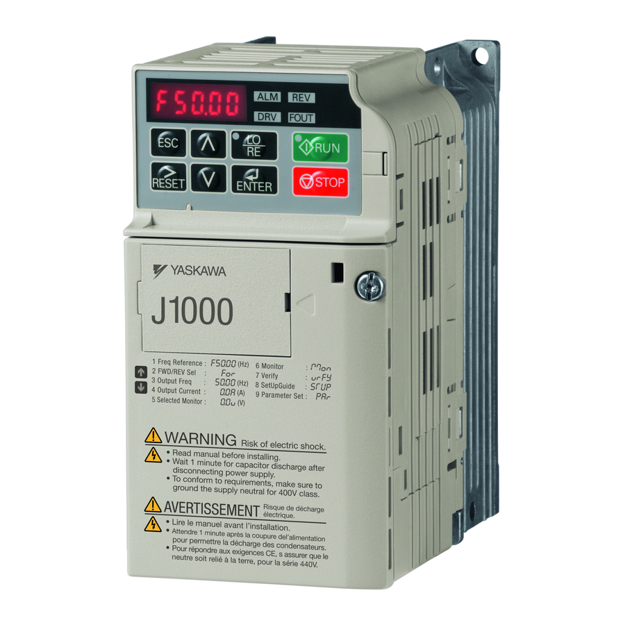
YASKAWA j1000 Quick Start Manual
Compact variable frequency drive
Hide thumbs
Also See for j1000:
- Technical manual (261 pages) ,
- Quick start manual (38 pages) ,
- Installation manual (25 pages)
Table of Contents
Advertisement
J1000
Quick Start Guide
1 Safety Instructions and General Warnings . . . . . . . . . . 4
2 Mechanical Installation . . . . . . . . . . . . . . . . . . . . . . . . . . 9
3 Electrical Installation . . . . . . . . . . . . . . . . . . . . . . . . . . . 11
4 Keypad Operation . . . . . . . . . . . . . . . . . . . . . . . . . . . . . 16
5 Start Up . . . . . . . . . . . . . . . . . . . . . . . . . . . . . . . . . . . . . . 18
6 Parameter Table . . . . . . . . . . . . . . . . . . . . . . . . . . . . . . . 22
7 Troubleshooting . . . . . . . . . . . . . . . . . . . . . . . . . . . . . . 25
TOEP C710606 27
J1000 Quick Start Guide
3
Advertisement
Table of Contents

Related Manuals for YASKAWA j1000


Summary of Contents for YASKAWA j1000
- Page 1 7 Troubleshooting ......25 TOEP C710606 27 J1000 Quick Start Guide...
-
Page 2: Safety Instructions And General Warnings
Yaskawa must be supplied to the end user with appropriate warnings and instructions as to the safe use and operation of that part. Any warnings provided by Yaskawa must be promptly provided to the end user. Yaskawa offers an express warranty only as to the quality of its products in conforming to standards and specifications published in the manual. - Page 3 • Do not attempt to modify or alter the drive in any way not explained in this manual. Failure to comply could result in death or serious injury. Yaskawa is not responsible for any modification of the product made by the user. This product must not be modified.
- Page 4 Failure to comply may result in minor or moderate injury from the main body of the drive falling. Burn Hazard • Do not touch the heatsink or braking resistor hardware until a powered-down cooling period has elapsed. TOEP C710606 27 J1000 Quick Start Guide...
- Page 5 • Do not modify the drive circuitry. Failure to comply could result in damage to the drive and will void warranty. Yaskawa is not responsible for modification of the product made by the user. This product must not be modified.
- Page 6 The drive internal motor overload protection is UL listed and in accordance with the NEC and CEC. The setup can be done using the parameters L1-01/02. For details refer to the tech- nical manual. TOEP C710606 27 J1000 Quick Start Guide...
-
Page 7: Mechanical Installation
• direct sunlight Altitude 1000 m or less Vibration 10 - 20 Hz at 9.8 m/s , 20 - 55 Hz at 5.9 m/s Orientation Install the drive vertically to maintain maximum cooling effects. TOEP C710606 27 J1000 Quick Start Guide... - Page 8 137.5 BA0010 145.5 2A0001 67.5 2A0002 67.5 2A0004 38.5 99.5 2A0006 58.5 119.5 2A0010 120.5 2A0012 137.5 2A0020 134.5 4A0001 72.5 4A0002 90.5 4A0004 137.5 4A0005 145.5 4A0007 145.5 4A0009 145.5 4A0011 134.5 TOEP C710606 27 J1000 Quick Start Guide...
-
Page 9: Electrical Installation
Monitor output 0 to +10 Vdc (2mA) (default setting) (Output frequency) Analog input Symbols: Indicates a main circuit terminal Use twisted pair cables Indicates a control circuit terminal. Use shielded twisted pair cables TOEP C710606 27 J1000 Quick Start Guide... - Page 10 MA, MB, MC 0.5 to 0.6 0.25 to 1.5 0.75 0.25 to 1.0 S1-S5, SC, +V, A1, 0.22 to 0.25 0.25 to 1.0 0.75 0.25 to 0.5 AC, AM TOEP C710606 27 J1000 Quick Start Guide...
- Page 11 EMC Standards Compliant Wiring of Single- and Three Phase Units Main and Control Circuit Wiring Wiring the Main Circuit Input Consider the following precautions for the main circuit input. TOEP C710606 27 J1000 Quick Start Guide...
- Page 12 • Use twisted-pair or shielded twisted-pair cables for control circuits to prevent operating faults. • Ground the cable shields with the maximum contact area of the shield and ground. • Cable shields should be grounded on both cable ends. TOEP C710606 27 J1000 Quick Start Guide...
- Page 13 30 Vdc, 10 mA to 1 A Relay 250 Vac, 10 mA to 1 A Digital output common Output AM Analog monitor output 0 to 10 Vdc (2 mA or less), Resolution: 1/256 (8 bit) Monitor Output Monitor common TOEP C710606 27 J1000 Quick Start Guide...
-
Page 14: Keypad Operation
Off: The drive is in the Verify, Setup, Parameter Setting mode. On: The output frequency is displayed on the data screen. FOUT LED Light FOUT Off: Anything else than the output frequency is displayed on the data screen. TOEP C710606 27 J1000 Quick Start Guide... - Page 15 In the Parameter Setting Mode all Parameter Setting Mode drive parameters can be set up. <1> Switching to reverse: The LED is lit when LOCAL is selected TOEP C710606 27 J1000 Quick Start Guide...
-
Page 16: Start Up
Connect the load, run the motor and check the operation Fine tune and set application parameters if necessary. Final check the operation and verify the settings. Drive is ready to run the application TOEP C710606 27 J1000 Quick Start Guide... - Page 17 If the drive is operated in the REMOTE mode, make sure that the correct sources for the fre- quency reference and Run command are set in parameters b1-01/02 and that the drive is in the REMOTE mode. TOEP C710606 27 J1000 Quick Start Guide...
- Page 18 Operator keypad switch over between different reference values. Analog input Apply the frequency reference signal to terminal A1. Serial Communica- RS232C or RS422/485 Memobus communication tions Option Potentiometer Option Potentiometer Option TOEP C710606 27 J1000 Quick Start Guide...
- Page 19 After taking the steps listed above, the drive should be ready to run the application and per- form the basic functions. For details about more advanced setup refer to the technical man- ual. TOEP C710606 27 J1000 Quick Start Guide...
-
Page 20: Parameter Table
Sets the DC Injection Braking cur- Injection 0: Heavy Duty (HD) b2-02 rent as a percentage of the drive Normal/ Braking Constant torque applications rated current. C6-01 Heavy Duty Current 1:Normal Duty (ND) Selection Variable torque application TOEP C710606 27 J1000 Quick Start Guide... - Page 21 Prot. Sel. 2:Standard blower cooled motor Motor E2-02 Motor rated slip in hertz (Hz). Motor Sets the motor overload protection Rated Slip L1-02 Overload time in min. Normally no change is Prot. Time necessary. TOEP C710606 27 J1000 Quick Start Guide...
- Page 22 Minor fault (Alarm) (ON: Alarm displayed) 1: Digital input 2 U1-10 (terminal S2 enabled) 1: Digital input 3 (terminal S3 enabled) 1: Digital input 4 (terminal S4 enabled) 1: Digital input 5 (terminal S5 enabled) TOEP C710606 27 J1000 Quick Start Guide...
-
Page 23: Troubleshooting
• Short circuit or ground fault on the drive output side • The load is too heavy. Overcurrent • The accel./decel. times are too short. • Wrong motor data or V/f pattern settings. • A magnetic contactor was switched at the output. TOEP C710606 27 J1000 Quick Start Guide... - Page 24 Undervoltage • The power supply failed or one input phase has been lost. • The power supply is too weak. DC Charge Circuit Fault The charge circuit for the DC bus is broken. TOEP C710606 27 J1000 Quick Start Guide...
- Page 25 • Correct the values set to b1-01 and b1-02. • b1-02=2 oPE10 • Check the V/f pattern settings. The V/f pattern setting is incorrect. • Refer to the instruction manual for more details. TOEP C710606 27 J1000 Quick Start Guide...
- Page 26 7 Troubleshooting TOEP C710606 27 J1000 Quick Start Guide...
- Page 27 Revision History The revision dates and numbers of the revised manuals are given on the bottom of the back cover. MANUAL NO. TOEP C710606 27A Published in Japan January 2008 08-1 Date of original publication Date of publication Date of Publication Rev. No. Section Revised Contents January 2008...
Need help?
Do you have a question about the j1000 and is the answer not in the manual?
Questions and answers