Table of Contents
Advertisement
Quick Links
Manual
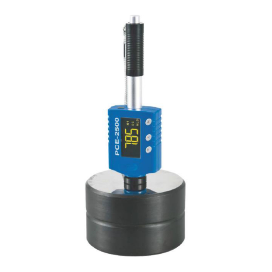
Durometer PCE-2500
Version 1.2
26.02.2016
PCE Americas Inc.
711 Commerce Way
Suite 8
Jupiter
FL-33458
USA
From outside US: +1
Tel: (561) 320-9162
Fax: (561) 320-9176
info@pce-americas.com
www.pce-instruments.com/english
www.pce-instruments.com
PCE Instruments UK Ltd.
Units 12/13
Southpoint Business Park
Ensign way
Hampshire / Southampton
United Kingdom, SO31 4RF
From outside UK: +44
Tel: (0) 2380 98703 0
Fax: (0) 2380 98703 9
info@pce-instruments.com
Advertisement
Table of Contents

Related Manuals for PCE Health and Fitness PCE-2500


Summary of Contents for PCE Health and Fitness PCE-2500
- Page 1 Hampshire / Southampton United Kingdom, SO31 4RF From outside US: +1 From outside UK: +44 Tel: (561) 320-9162 Tel: (0) 2380 98703 0 Fax: (561) 320-9176 Fax: (0) 2380 98703 9 info@pce-americas.com info@pce-instruments.com www.pce-instruments.com/english www.pce-instruments.com Manual Durometer PCE-2500 Version 1.2 26.02.2016...
-
Page 2: Table Of Contents
Manual Content Introduction ......................4 Forewords ........................... 4 1.1.1 History ............................4 1.1.2 Leeb Hardness Test (definition) ..................... 4 Notation of Leeb’s Hardness ......................5 1.1.3 Safety information ....................5 Features and Application ..................6 Introduction ..........................6 Specifications ..........................6 Applications .......................... - Page 3 Manual 7.12 Calibration..........................16 7.12.1 Calibration mode .......................... 16 7.12.2 Adjust ............................16 7.12.3 Calibration on ..........................17 7.12.4 Calibration off ..........................17 7.12.5 Calibration for DL probe ....................... 17 7.13 Prompt Sound ........................... 17 Changing impact body ..................18 Take a measurement .....................
-
Page 4: Introduction
Manual Introduction Thank you for purchasing a PCE-2500 hardness tester from PCE Instruments. Forewords 1.1.1 History The Leeb measuring method was first brought into measurement technology in 1978. It is defined as the quotient of an impact body’s rebound velocity over its impact velocity, multiplied by 1000. -
Page 5: Notation Of Leeb's Hardness
Manual Notation of Leeb’s Hardness 1.1.3 When measuring the hardness of a sample material using the traditional static hardness testing method, a change of applied pressure will result in a change in the hardness reading. This will also happen during a Leeb’s Hardness test when one changes the impact device. -
Page 6: Features And Application
Manual Features and Application Introduction This instrument is an advanced state-of-the-art palm sized metal hardness tester with many new features which are light weight, easy operation, integrated design, high contrast display, low operating temperature, auto compensating for impact direction and etc. It can be widely used for measuring hardness of almost all ferrous and non-ferrous metal materials for scale of Leeb hardness, Rockwell C, B &A, Brinell, Vickers, Shore and Strength. -
Page 7: Device Description
Manual Device description Symbols and Illustrations Symbols and Illustraions Symbols Illustrations Leeb hardness value used with impact device D Leeb hardness value used with impact device DL Brinell hardness value Rockwell B hardness value Rockwell C hardness value Shore hardness value Vickers hardness value Rockwell A hardness value σb (N/mm2... -
Page 8: Preparation Before Measuring
Manual Preparation before Measuring Requirements for the sample 6.1.1 The surface temperature of the sample should be less than 120 °C. 6.1.2 The sample must feature a metallic smooth, ground surface, in order to eliminate erroneous measurements brought about by coarse grinding or lathe scoring. The roughness of the finished surface should not exceed 2 µm. -
Page 9: Supporting The Samples During Testing
Manual Supporting the Samples during testing When measuring hardness with this tester, the following has to be noticed: Despite the low mass of the impact body and low impact energy, a relatively large impact force of short duration is generated when the impact body hits the measuring surface. -
Page 10: Operation
Manual Operation Button description ▼ ▲ ► - Menu key, press it to enter - Upward key, press it to move cursor upward - Press it to switch on the main menu - Press and hold it to save the settings and tester - Downward key, press it to exit... -
Page 11: Diagram Of Operation
Manual Diagram of operation... -
Page 12: Power On The Instrument
Manual Power on the instrument Method 1: Press ► to turn on the instrument. Method 2: Push the loading tube toward tester slowly until locking the impact body inside the probe. Then let the loading tube back to original position. The instrument will be powered on. The screen will display the measuring window after it is switched on, you can start measurement. -
Page 13: Display Modes
Manual Display Modes In measuring mode, press ▲ in turn to switch between different display modes. Settings Press ▼ to enter the Menu screen. Press ▼ or ▲ to select Settings and press ► to enter. Press ▼ or ▲ again to select in cycle: Exit →... -
Page 14: Impact Device
Manual 7.6.1 Impact Device There are two kinds of impact device can be selected. Impact device D is for normal application and DL is for some specific situation, such as narrow step or deep blind hole. When you select impact device DL, you need to change impact body D to DL. -
Page 15: Memory
Manual any key to save and return to the Measure screen. The symbol will display on the instrument screen after Upper/Lower limit alarm is enabled. 7.11 Memory Press ▼ to enter the Menu screen. Press ▼ or ▲ to select Memory and press ► to enter. Press ▼ or ▲ again to select in cycle: X(Off) →... -
Page 16: Calibration
Manual 7.12 Calibration After long time of use, the ball tip on impact body may worn which would lead inaccuracy. In order to compensate such error, the tester is designed to re-calibrate by user. Press ▼ to enter the Menu screen. Press ▼ or ▲ to select Calibration and press ► to enter. Press ▲ to select in cycle: X(Off) →... -
Page 17: Calibration On
Manual 7.12.3 Calibration on In calibration menu, the current item is “”(Calibration On), press ► to switch on the Calibration and return to the Menu screen. After Calibration is done, the symbol will display at upper of the measuring screen. 7.12.4 Calibration off If you want to switch off the calibration, in calibration menu, press ▲... -
Page 18: Changing Impact Body
Manual Changing impact body This tester has a very unique feature, which impact device can convert between D and DL simply by changing impact body. This two-in-one probe is equivalent to two individual probes. With this optional accessory, you can take measurement at very narrow surface such as slot bottom, gear tooth that probe D cannot match. -
Page 19: Take Measurement
Manual Take measurement Place the tester onto the surface of object to be measured by the support ring. Please note: the proper way of holding is important for obtaining better readings. Attention: the tester must be placed against object surface firmly and perpendicularly. A slight gap between support ring of tester and surface of object will lead inaccurate reading. -
Page 20: Disposal
Manual 11 Disposal For the disposal of batteries, the 2006/66/EC directive of the European Parliament applies. Due to the contained pollutants, batteries must not be disposed of as household waste. They must be given to collection points designed for that purpose. In order to comply with the EU directive 2012/19/EU we take our devices back.
Need help?
Do you have a question about the PCE-2500 and is the answer not in the manual?
Questions and answers