Advertisement
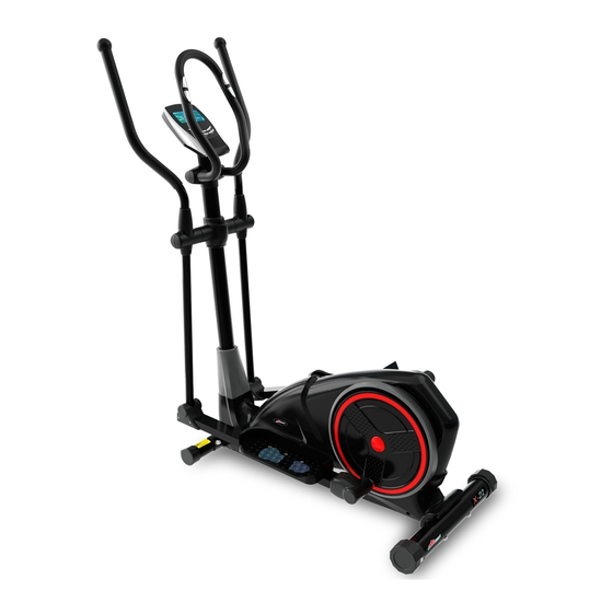
X-22 CROSS TRAINER
OWNER'S MANUAL
Product may vary slightly from the item pictured due to model upgrades
Read all instructions carefully before using this product. Retain this owner's manual for future
reference.
NOTE: This manual may be subject to updates or changes. Up to date manuals are available through our website at
www.lifespanfitness.com.au
Advertisement
Table of Contents

Related Manuals for LifeSpan X-22


Summary of Contents for LifeSpan X-22
- Page 1 X-22 CROSS TRAINER OWNER’S MANUAL Product may vary slightly from the item pictured due to model upgrades Read all instructions carefully before using this product. Retain this owner’s manual for future reference. NOTE: This manual may be subject to updates or changes. Up to date manuals are available through our website at...
-
Page 2: Table Of Contents
TABLE OF CONTENTS IMPORTANT SAFETY INSTRUCTIONS CARE INSTRUCTIONS ASSEMBLY INSTRUCTIONS DISPLAY MANUAL EXERCISE GUIDE EXPLODED DIAGRAM PARTS LIST WARRANTY... -
Page 3: Important Safety Instructions
1. IMPORTANT SAFETY INSTRUCTIONS WARNING - Read all instructions before using this machine. It is important your machine receives regular maintenance to prolong its useful life. Failing to regularly maintain your machine may void your warranty. Please keep this manual with you at all times It is important to read this entire manual before assembling and using the equipment. -
Page 4: Care Instructions
Wear suitable clothing while using the equipment. Avoid wearing loose clothing that may get caught in the equipment or that may restrict or prevent movement. This equipment is designed for indoor and family use only Care must be taken when lifting or moving the equipment so as not to injure your back. Always keep this instruction manual and assembly tools at hand for reference. -
Page 5: Assembly Instructions
3. ASSEMBLY INSTRUCTIONS STEP 1: 1. Attach the Front stabilizer (3) to the main frame (1) with carriage bolt (20), arc washer (21) and acorn nut (22). 2. Attach the Rear stabilizer (2) to the main frame (1) with Allen bolt (55) and arc washer (54). - Page 6 STEP 2: Note: Please exercise caution not to crush the main cable during assembly 1. Insert the front shield (14) into the handlebar post (4). 2. Connect the sensor wire (26) well with extension wire (25) 3. Fix the handlebar post (4) to the main frame (1) with Allen bolt (23) and arc washer (21).
- Page 7 STEP 3: 1. Connect the Swing tube (6L/R) and Pedal support (5L/R) with Bolt (39),Flat washer (53), Flat washer (40) and Nylon nut (41). Do not tighten the bolt yet 2. Attach the left and right Swing tube (6L/R) to the shaft on Handlebar post (4) with Bolt (28), Spring washer (27) and Flat washer (63).
- Page 8 STEP 4: 1. Attach the pedals (17L/R) to the pedal supports (5L/R) with hex bolts (45), flat washer (46) and nylon nuts (61).
- Page 9 STEP 5: 1. Attach the connecting cover (18L/R) onto the pedal support (5L/R) with cross screw (36) as shown. ttach the connecting joint cover (19a/b) on the connecting joint (43L/R) with cross screw (44) as shown.
- Page 10 STEP 6: 1. Attach the handlebar (7L/R) on to the swing bar (6L/R) with the carriage bolt (34) and nylon nut (35). 2. Attach the swing bar cover (13L/R-1)( 13L/R-2) to the connecting joint between the handlebar (7L/R) and swing bar (6L/R) using cross tapping screw (57) as shown. 3.
- Page 11 STEP 7: 1. Connect the handlebar pulse wire (47) to the extension wire (25) with the wires coming from the computer (10), and then attach the computer (10) onto the computer bracket of the handlebar post (4) with cross screw (49). Attach the Handlebar post shield (58b) to the Handlebar post shield (58a) with cross screw (36) and cross tapping screw (57) as shown.
-
Page 12: Display Manual
4. DISPLAY MANUAL Input Power Plug in the adaptor to the equipment then the computer will produce a beep sound and turn on the computer at the Manual mode. Program select and setting value 1. Use the UP or DOWN keys to select program mode and then press ENTER to confirm your exercise mode. 2. - Page 13 always default to age 35. 9. TARGET HEART RATE (TARGET PULSE): The heart rate you should maintain is called your Target Hear Rate in beats per minute. 10. PULSE RECOVERY: During the START stage, leave the hands holding on grips or leave the chest transmitter attached and then press “PULSE RECOVERY”...
- Page 14 3. DOWN key: a) Press the key to decrease the resistance during exercise mode. b) During the setting mode, press the key to decrease the value of Time, Distance, Calories, Age and select Gender and Program. 4. ENTER key: a) During the setting mode, press the key to accept the current data entry. b) At the stop mode, by holding this key for over two seconds the user can reset all values to zero or default value.
- Page 15 ENTER key to confirm your desired CALORIES. 6. The PULSE will flash and then you can press UP or DOWN keys to set your exercise PULSE. Press ENTER key to confirm your desired Pulse. 7. Press the START/STOP key to begin exercise. Preset Program: Steps, Hill, Rolling, Valley, Fat Burn, Ramp, Mountain, Intervals, Random, Plateau, Fartlek, Precipice Program PROGRAM 2 to 13 is the preset programs.
- Page 16 3. The column 1 will flash, and then use the UP/DOWN keys to create your personal exercise profile. Press ENTER to confirm your first column of exercise profile. The default level is load 1. 4. The column 2 will flash, and then use the UP/DOWN keys to create your personal exercise profile. Press ENTER to confirm your second column of exercise profile.
- Page 17 2. Press the ENTER key to enter your workout program 3. The AGE will flash at P18 to P21 programs and you can press UP or DOWN keys to set your AGE. The default age is 35. 4. At program 22, the TARGET PULSE will flash and you can press UP or DOWN keys to set your TARGET PULSE between 80 to 180.
- Page 18 7. The PULSE will flash and then you can press UP or DOWN keys to set your exercise PULSE. Press ENTER key to confirm your desired Pulse. 8. Press the START/STOP key to begin exercise. NOTE: 1. WATT = TORQUE (KGM) * RPM * 1.03 2.
- Page 19 9. Press START/STOP key to begin exercise. Operation guide: 1. Sleep Mode: The computer will enter the sleep mode when there is no signal input and no keys be pressed after 4 minutes. You can press any key to wake up the computer. 2.
- Page 20 PROGRAM 4 PROGRAM 5 PROGRAM 6 ROLLING VALLEY FAT BURN PROGRAM 7 PROGRAM 8 PROGRAM 9 RAMP MOUNTAIN INTERVALS PROGRAM 10 PROGRAM 11 PROGRAM 12 RANDOM PLATEAU FARTLEK PROGRAM 13 PRECIPICE USER SETTING PROGRAM PROGRAM 14 USER 1 PROGRAM 15 USER 2 PROGRAM 16 USER 3...
- Page 21 PROGRAM 17 USER 4 HEART RATE PROGRAM PROFILES: PROGRAM 18 55% H.R.C. PROGRAM 19 65% H.R.C. PROGRAM 20 75% H.R.C. PROGRAM 21 85% H.R.C. PROGRAM 22 TARGET H.R.C. WATT CONTROL PROGRAM PROGRAM 23 WATT CONTROL...
- Page 22 BODY FAT TEST PROGRAMS: PROGRAM 24 BODY FAT (STOP MODE) BODY FAT (START MODE) One of the Following Six Profiles Will Display Automatically after Measuring Your BODY FAT: Workout Time: 40 minutes Workout Time: 40 minutes Workout time: 20 minutes Workout Time: 40 minutes Workout Time: 40 minutes Workout time: 20 minutes...
-
Page 23: Exercise Guide
5. EXERCISE GUIDE PLEASE NOTE: Before beginning any exercise program, consult your physician. This is important especially if you are over the age of 45 or individuals with pre-existing health problems. The pulse sensors are not medical devices. Various factors, including the user’s movement, may affect the accuracy of heart rate readings. -
Page 24: Workout Guidelines
After warming up, increase the intensity to your desired exercise program. Be sure to maintain your intensity for maximum performance. Breathe regularly and deeply as you exercise. Cool Down Finish each workout with a light jog or walk for at least 1 minute. Then complete 5 to 10 minutes of stretching to cool down. -
Page 25: Exploded Diagram
6. EXPLODED DIAGRAM... -
Page 26: Parts List
7. PARTS LIST DESCRIPTION DESCRIPTION Main frame Nylon nut M8 Rear stabilizer Cross screw ST4.2X18 Axle bushing φ12Xφ32 X15 Front stabilizer Plastic bushing φ24X 16 Xφ Handlebar post 16.1 5L/R Pedal support (L/R) Hex bolt M10X80 6L/R Swing bar(L/R) Flat washer D10Xφ20X2 7L/R Handlebar (L/R) Nylon nut M10... -
Page 27: Warranty
8. WARRANTY AUSTRALIAN CONSUMER LAW Many of our products come with a guarantee or warranty from the manufacturer. In addition, they come with guarantees that cannot be excluded under the Australian Consumer Law. You are entitled to a replacement or refund for a major failure and compensation for any other reasonably foreseeable loss or damage. - Page 28 Hand Pulse Technology Lifespan Fitness exercise equipment come equipped with hand pulse sensors which are used to pick up tiny EKG/ECG signals that run through the body when your heart beats. These electrical EKG/ECG signals are very small and that they must be amplified 1000 times to make the signal useful for the computer to display your pulse.
Need help?
Do you have a question about the X-22 and is the answer not in the manual?
Questions and answers