Table of Contents
Advertisement
Quick Links
Advertisement
Table of Contents

Related Manuals for Gossen MetraWatt METRA HIT 1A


Summary of Contents for Gossen MetraWatt METRA HIT 1A
- Page 1 Operating Instructions METRA HIT 1A/2A 3-349-305-15 Analog Multimeter 5/8.11...
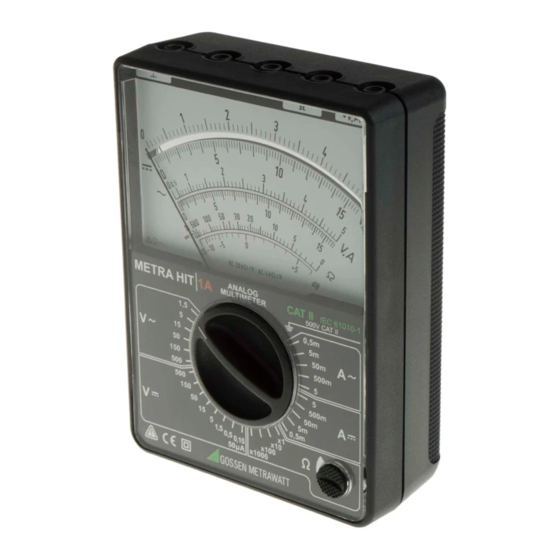
- Page 2 1 Common connection for all measuring ranges (instrument earth) 2 METRA HIT 2A: connection for highest current measuring range 15 A 3 Connection for resistance measurement and capacitance measurement (negative potential) 4 Connection for all voltage and current ranges except for METRA HIT 2A: here current measuring range up to 1.5 A 5 Catch for locking the bottom part of the instrument 6 Set screw for mechanical zero setting of the pointer 7 Potentiometer knob...
-
Page 3: Table Of Contents
Contents Page Safety Features and Precautions ........4 Application ................6 Description ................7 Operation ................8 Controls ..................8 Starting the Instrument (Ω Measurement only) .........9 Voltage Measurement ..............10 4.3.1 DC and AC Voltages up to 500 V ...........11 Current Measurement ..............12 4.4.1 DC and AC Voltages (METRA HIT 2A: up to 1.5 A) ......12 4.4.2 METRA HIT 2A: Direct and Alternating Currents up to 15 A ....13 Resistance Measurements ............14 Estimated Capacitance Measurement ..........16... -
Page 4: Safety Features And Precautions
Safety Features and Precautions You have selected an instrument which provides you with a high level of safety. This instrument fulfills the requirements of the applicable Euro- pean and national EC guidelines. We confirm this with the CE marking. The relevant declaration of conformity can be obtained from GMC-I Messtechnik GmbH. - Page 5 • The instrument may only be used for current measurement in power systems if the electrical circuit is protected with a fuse or a circuit breaker with a rating of up to 20 A. In order to conform to the CAT requirements, two fuse links have been fitted for the ranges mA und A.
-
Page 6: Application
Meaning of symbols on the instrument Warning concerning a point of danger (Attention: observe documentation) Continuous, doubled or reinforced insulation CAT II Measuring category II instrument 500 V Ground Fuse Indicates EU conformity Application The multimeter is suited for voltage, current and resistance mea- surements and for the rough measurement of capacitance. -
Page 7: Description
Description The multimeter has measuring ranges for direct and alternating voltage, direct and alternating current and resistance. Capaci- tance values can be ascertained by rough measurements. All the measuring ranges are selected by means of the central range switch. They are clearly arranged in the rotary section of the switch. -
Page 8: Operation
Operation Controls Measuring range switch The multimeter has only one rotary switch by which all the mea- suring ranges are selected. The meter can be switched from the direct voltage ranges to the corresponding alternating voltage ranges, or from the direct current ranges to the corresponding alternating current ranges, without switching off the measured value. -
Page 9: Starting The Instrument (Ω Measurement Only)
Potentiometer knob The rotary knob is used to set the full deflection 0 Ω when mea- suring resistance as described in chapter 4.5 and capacitance according to chapter 4.6. 4.2 Starting the Instrument (Ω Measurement only) Inserting the battery The bottom half must be removed from the instrument in order to install or exchange the battery. -
Page 10: Voltage Measurement
• If necessary, adjust the set screw on the rear of the instru- ment with a screwdriver to correct the setting. Battery check ➭ Set the range switch to the „Ω x 1“ position. ➭ Short-circuit connecting sockets „⊥“ and „Ω“ using a mea- suring lead. -
Page 11: Dc And Ac Voltages Up To 500 V
4.3.1 DC and AC Voltages up to 500 V ➭ Set range switch to the posi- tion 500 V or 500 V . ➭ Plug test leads into the instru- ment; (black) test lead to socket „⊥“ and (red) lead to socket „+ V, “. -
Page 12: Current Measurement
4.4 Current Measurement Attention! The multimeter must always be connected into the lead the voltage of which is the lowest relative to earth. For safety reasons, the voltage relative to earth must not ex- ceed 500 V CAT II! Observe the overload limits, see tables on page 23. -
Page 13: Metra Hit 2A: Direct And Alternating Currents Up To 15 A
➭ Read off the measured value: METRA HIT 1A: for DC on scale 0 ... 15 V,A , for AC on scale 0 ... 15 V,A . METRA HIT 2A: for DC on scale 0 ... 15 V,A , for AC on scale 0 ... -
Page 14: Resistance Measurements
4.5 Resistance Measurements Resistance is measured with DC voltage from the 1.5 V mignon cell. The table of measuring ranges in chapter 5 gives the maximum mea- suring currents for full deflection and a battery voltage of 1.5 V. Socket polarity is as follows: Positive pole on socket „⊥“... - Page 15 Attention! Only voltage-free objects may be measured. External voltages falsify the measuring results and might also damage the instrument! ➭ Read off the value displayed on the Ω scale and multiply by the factor according to the adjusted measuring range. If possible, the measuring range should be selected in such a way as to obtain a reading in the range 5 ...
-
Page 16: Estimated Capacitance Measurement
4.6 Estimated Capacitance Measurement Capacitance values can be determined in the resistance ranges by estimated measurement. When doing so, proceed exactly as if measuring resistance in accordance with chapter 4.5. Resis- tance R is to be replaced by the capacitance to be measured, after prior discharge. -
Page 17: Measurement Of Gain And Attenuation
4.7 Measurement of Gain and Attenuation In communications engineering, gain or attenuation is almost exclusively given as a logarithm of the ratio between a measured voltage and a given reference voltage in dB. In recurrent net- works, it is thereby possible to determine the total gain or attenu- ation in a simple manner by adding or subtracting the individual values. -
Page 18: Testing Diodes And Transistors
Example: For a 1 kHz superposed AC voltage, a series-connected capaci- tor of C = 0.0056 μF = 5.6 nF results for the 50 V measuring range. Attention! The capacitor is loaded up to the value of the DC volt- age component. -
Page 19: Technical Characteristics
0 dB 0.775 V in the range of 1.5 V ; 0 dB Input resistance in relation to voltage : 20.0 kΩ/V 4.0 kΩ/V METRA HIT 1A: Current Measuring Ranges Voltage Drop approx. Current 50.00 μA 0.158 V — 0.50 mA 1.15... - Page 20 METRA HIT 2A: Current Measuring Ranges Voltage Drop approx. Current 50 μA 0.158 V — 1.5 mA 1.16 1.21 15 mA 1.25 1.25 150 mA 1.25 1.25 1.5 A 1.95 1.95 15 A 0.43 0.49 Resistance Measuring Ranges Value at Mid-Scale Max.
- Page 21 Reference Conditions +23 °C ±2 K Ambient temperature Position of use horizontal Frequency 40 ... 60 Hz Wave shape : sinusoidal Relative humidity 40 ... 60% The instrument features half-wave rectification and is calibrated in r.m.s. values. It evaluates the arithmetical mean of a half-wave and indicates different values for undulatory voltage or current, depending on the polarity of connection.
- Page 22 500 V Test voltage 3.5 kV~ Contamination level Fuses replaceable METRA HIT 1A: F1: FF630mA/700V AC (50 kA), 6.3 x 32 (Article number: Z109J) F2: FF6,3A/500V AC (50 kA), 6.3 x 32 (Article number: Z109K) METRA HIT 2A: F1: FF1,6A/700V AC (50 kA), 6.3 x 32 (Article number: Z109E) F2: FF16A/500V AC (50 kA), 6.3 x 32...
- Page 23 METRA HIT 1A: Overload capacity Range loadable up to Range loadable up to 0.15 V – 20 V — — V – 50 V — — V – 100 V 25 V V – 150 V 50 V 15.0 V –...
- Page 24 Mechanical Design Scale length A, V – 0 ... 5.0: approx. 83 mm A, V – 0 ...15.8: approx. 77 mm A, V 0 ... 5.0: approx. 67 mm A, V 0 ... 15.8: approx. 59 mm Ω ∞ ... 0: approx.
-
Page 25: Maintenace
Maintenace 6.1 Battery The state of the battery should be checked from time to time. A discharged or decomposing battery should not be left inside the instrument. The battery should be checked and changed in the manner described in chapter 4.2. 6.2 Housing No special maintenance is required for the housing. - Page 26 Melting Fuse F1 for the mA Range and 0.15 V Range The inserted F1 melting fuse for the measuring circuit up to 0.5 A (for METRA HIT 1A) or 1.5 A (for METRA HIT 2A) can be checked for continuity in the resistance measuring ranges, preferrably in the Ω...
-
Page 27: Device Return And Environmentally Compatible Disposal
6.4 Device Return and Environmentally Compatible Disposal The instrument is a category 9 product (monitoring and control instrument) in accordance with ElektroG (German Electrical and Electronic Device Law). This device is not subject to the RoHS directive. We identify our electrical and electronic devices (as of August 2005) in accordance with WEEE 2002/96/EG and ElektroG with the symbol shown to the right per DIN EN 50419. -
Page 28: Standard Equipment
Standard Equipment Analog multimeter without battery, without cable set GMC-I Messtechnik GmbH... -
Page 29: Recalibration
Recalibration The respective measuring task and the stress to which your measuring instrument is subjected affect the ageing of the com- ponents and may result in deviations from the guaranteed accu- racy. If high measuring accuracy is required and the instrument is fre- quently used in field applications, combined with transport stress and great temperature fluctuations, we recommend a relatively short calibration interval of 1 year. -
Page 30: Repair And Replacement Parts Service Dkd Calibration Center
Repair and Replacement Parts Service DKD Calibration Center and Rental Instrument Service When you need service, please contact: GMC-I Service GmbH Service Center Thomas-Mann-Strasse 20 90471 Nürnberg • Germany Phone +49 911 817718-0 +49 911 817718-253 E-Mail service@gossenmetrawatt.com www.gmci-service.com This address is only valid in Germany. Please contact our representatives or subsidiaries for service in other countries. -
Page 31: Product Support
Product Support When you need support, please contact: GMC-I Messtechnik GmbH Hotline Produktsupport Phone +49 911 8602-0 +49 911 8602-709 E-Mail support@gossenmetrawatt.com GMC-I Messtechnik GmbH... - Page 32 Edited in Germany • Subject to change without notice • A pdf version is available on the Internet Phone +49 911 8602-111 GMC-I Messtechnik GmbH +49 911 8602-777 Südwestpark 15 E-Mail info@gossenmetrawatt.com 90449 Nürnberg • Germany www.gossenmetrawatt.com...
Need help?
Do you have a question about the METRA HIT 1A and is the answer not in the manual?
Questions and answers