Table of Contents
Advertisement
Quick Links
Advertisement
Table of Contents

Related Manuals for Gossen MetraWatt METRAmax 2


Summary of Contents for Gossen MetraWatt METRAmax 2
- Page 1 Operating instructions METRAmax 2 3-348-734-02 Analog multimeter 3/3.97...
- Page 2 GOSSEN-METRAWATT...
-
Page 3: Table Of Contents
Contents Page Safety features and safety precautions ....4 Description ..............5 Operation ..............6 3.1 Operating controls .............. 6 3.2 Getting started ..............6 3.2.1 Connecting the battery ............6 3.2.2 Checking the mechanical zero ..........7 3.2.3 Checking the electrical zero ........... 7 3.2.4 Battery test ................ -
Page 4: Safety Features And Safety Precautions
• Case and test leads must be in good condition, e.g. no cracks or broken spots. • The METRAmax 2 must not be used for measurements on circuits with corona discharge (high voltage!). • Be particularly careful when measuring on HF circuits. -
Page 5: Description
Description On the METRAmax 2, the measuring ranges are selected with a sliding function switch and a rotary range selector switch. The scale is mirror-backed. The rugged plastic case and the spring-loaded jewel bearings of the stray-field-insensitive moving-coil movement with core magnet protect the meter against damages in the case of severe mechan- ical stress. -
Page 6: Operation
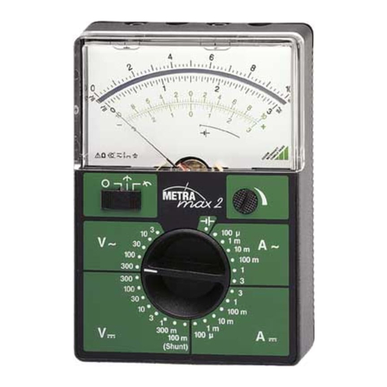
Operation 3.1 Operating controls 6F22 1 Adjustment screw for the mechanical zero ( OFF on scale) 2 Sliding function switch 3 Rotary range selector switch 4 Rotary knob for mid-scale setting of the electrical zero 5 Safety connection sockets 6 Nose to open the meter 7 Battery compartment 3.2 Getting started 3.2.1 Connecting the battery... -
Page 7: Checking The Mechanical Zero
3.2.2 Checking the mechanical zero The METRAmax 2 must not be connected when checking the me- chanical zero. • Set the sliding function switch 2 to the "0" position •... -
Page 8: Voltage Measurement
• Set the rotary range selector switch 3 to the corresponding measuring range: V 300 V ... 100 mV • Connect the METRAmax 2 • Read the measured value: black scale Operating mode: Electrical zero at mid-scale • Set the sliding function switch 2 to the position •... -
Page 9: Ac Voltage Measurement With Superimposed Dc Voltage Component
• Connect the METRAmax 2 • Read the measured value: black scale To keep the influence of the frequency as low as possible, the con- nection socket " " should be connected to the ground potential as directly as possible or to lowest point with respect to ground. -
Page 10: Current Measurement
3.4 Current measurement For all current measurements, connect the METRAmax 2 in series with the consumer in the line having the lower potential to ground. 3.4.1 Direct DC current measurement Operating mode: Electrical zero at left • Set the sliding function switch 2 to the position •... -
Page 11: Ac Current Measurement
• Set the rotary range selector switch 3 to the following position: 100 V • Connect the METRAmax 2 • Read the measured value: back scale Operating mode: Electrical zero at mid-scale • Set the sliding function switch 2 to the position •... -
Page 12: Specifications
Specifications Measuring ranges DC and AC Internal resistance DC and AC Voltage voltage voltage drop 100 µA / 100 mV 10 MΩ 55 mV 300 mV 10 MΩ 1 mA / 55 mV 10 MΩ 10 mA / 55 mV 100 mA / 55 mV 3 V /... - Page 13 Power supply Battery 9-V flat cell battery, IEC 6F22, automatic battery switch-off after 45 min. Overload protection Fuse F3,15 H/250 V acc. to DIN VDE 0820 part 22/EN 60127-2 protects the circuits against over- load. The movement is protected by 2 diodes in inverse-parallel connec- tion.
-
Page 14: Maintenance
Maintenance 5.1 Battery replacement When a battery test reveals that the pointer no longer travels into the battery test section marked " ", the battery must be re- placed. Replace the exhausted battery with a new 9-V flat cell bat- tery according to IEC 6F 22. -
Page 15: Repair And Replacement Parts Service
Repair and replacement parts service When you need service, please contact: GOSSEN-METRAWATT GMBH Service Thomas-Mann-Straße 16 - 20 D - 90471 Nürnberg Telefon (09 11) 86 02 - 4 10 / 4 11 Telefax (09 11) 86 02 - 2 53 This address if for Germany only. - Page 16 Printed in Slovenia ⋅ Subject to change without notice GOSSEN-METRAWATT GMBH D – 90327 Nürnberg Company address: Thomas-Mann-Straße 16 – 20 D – 90471 Nürnberg Telefon (09 11) 86 02 – 0 Telefax (09 11) 86 02 – 6 69...
Need help?
Do you have a question about the METRAmax 2 and is the answer not in the manual?
Questions and answers