
Related Manuals for Gossen MetraWatt METRA HIT 28 S


Summary of Contents for Gossen MetraWatt METRA HIT 28 S
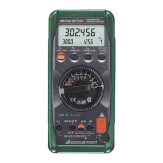
- Page 1 Operation Instructions METRA HIT 28S METRA HIT 29S 3-348-851-03 Precision Digital Multimeter 13/2.06...
- Page 2 → chapter 4 → chapter 2 → chapter 5 → chapter 3 → chapter 8ff → chapter 3 → chapter 3 → chapter 1 → chapter 2 max. 600 V ! LCD Display MENU/ON|OFF ON / OFF key Operating Mode Menu: Entry acknowledgment DATA|CLEAR Function key for measurement value store, delete and MIN-MAX...
- Page 3 17 16 Digital Display Symbols Main display with decimal point and indication of polarity Sub-displays with decimal point and indication of polarity Unit of measure Selected current type Continuous operation, symbol blinks for data transmission Low battery Acoustic signal on, buzzer activated for corresponding function Zero balancing Reference value 10 Memory display, “hold measurement value”...
-
Page 4: Table Of Contents
Contents Page Safety Features and Precautions ........6 Initial Start-Up ..............8 Selection of Measurement Functions and Measuring Ranges ............10 Automatic Measuring Range Selection ......10 Manual Measuring Range Selection ........10 Quick Measurements ............11 Triple Digital Display ............. 11 Measurement Value Storage “DATA”... - Page 5 Page Power Measurement with the METRA HIT 29S .....38 20.1 Power Measurement with Analog Signals I and V ....38 20.2 Energy Measurement with Pulses ........40 20.3 EnErGY Menu for Energy Measurement ......41 20.4 Exit Power/Energy Measurement ........42 20.5 Power Measurement with (Clip-On) Current Transformers .........42 Line Fault Recording with the METRA HIT 29S ....43 21.1...
-
Page 6: Safety Features And Precautions
Safety Features and Precautions You have selected an instrument which provides you with a high level of safety. This instrument fulfills the requirements of the applicable European and national EC guidelines. We confirm this with the CE marking. The relevant declaration of conformity can be obtained from GMC-I Gossen-Metrawatt GmbH. - Page 7 • Avoid working alone when taking measurements which involve contact hazards. Be certain that a second person is present. • The maximum allowable voltage between any given connector jack (7) and earth is equal to 600 V, category III or to 300 V, category IV.
-
Page 8: Initial Start-Up
Indicates EU conformity DKD calibration mark (red seal): Serial number B0730 German Calibration Service – Calibration Laboratory DKD-K- GOSSEN METRAWATT Calibration Laboratory 19701 99-02 Date of calibration Repair, Parts Replacement and Balancing When the instrument is opened, voltage conducting parts may be exposed. - Page 9 Operation with mains adapter (accessory equipment, not included as a standard feature) During power supply via mains adapter NA5/600, the inserted batteries are cut off electronically so that they rmay remain in the instrument, see also chapter 26.2. If rechargeable batteries are used, they must be charched outside the instrument.
-
Page 10: Selection Of Measurement Functions And Measuring Ranges
Selection of Measurement Functions and Measuring Ranges The rotary switch is coupled to the automatic socket blocking device, which makes two jacks available for each function (except mA and A: 3 jacks. The jack for the “mA” socket in the “A” function is half open). Before switching to the “mA”... -
Page 11: Quick Measurements
Quick Measurements If you wish to perform quicker measurements than those possible with the automatic measuring range selection function, make sure to establish the appropriate measuring range: • by manual measuring range selection, i. e. by selecting the measuring range with the best resolution, see chapter 3.2. -
Page 12: Measurement Value Storage "Data" (Hold & Compare)
Measurement Value Storage “DATA” (Hold & Compare) Measurement values can be automatically “frozen” with the DATA (Hold) function. This can be especially useful when your full attention is required for testing the measuring point with the test probes. After the measurement value has been acquired, and the appropriate “condition”... - Page 13 Condition Response at Instrument ⇓ Function Sub-Display Measuring Measurement Acoustic DATA DATA Meas. Function Value Signal DATA Value Switch on brief brief V, dB Store > 3.3% of MR dis- brief F, Hz (stabilized mea- dis- played surement value) Ω played <...
-
Page 14: Minimum And Maximum Value Storage "Min-Max" With Time Stamp
Minimum and Maximum Value Storage “MIN-MAX” with Time Stamp Minimum and maximum values can be read out at the sub- displays for long-term observation of measured quantities. ➭ If the DATA|CLEAR key is activated twice, current MIN and MAX values are displayed at the sub-displays. ➭... - Page 15 015.000 Current Measurement Value 015.123 DATA brief Current Measurement Value 015.345 DATA brief 015.345 015.345 Current Meas. Value 015.678 DATA brief 09:20:05 015.345 tMIN Current Meas. Value 015.986 DATA brief 09:20:05 015.986 tMAX DATA brief CLEAR long GMC-I Gossen-Metrawatt GmbH...
-
Page 16: Auto Select
Auto Select In the Auto Select switch position, the auto-select function (automatic selection of measuring function) allows for autonomous recognition of the measured quantity, which is applied between earth and the voltage jacks. An overview of possible measured quantities as well as the respective prerequisites for recognition can be found in the AUTO SELECT table on page 67. -
Page 17: Voltage Measurement
Voltage Measurement ➭ Depending upon the voltage to be measured, set the rotary switch to V or V 015.000 ➭ Connect the measurement cables as shown. The “⊥” jack should be grounded. ☞ Note! In the 600 V range, an intermittent acoustic signal sounds alarm if the measurement value exceeds 1000 V. -
Page 18: Transient Overvoltages
000.000 The instrument acknowledges zero balancing with an acoustic signal and “ ” (± 1 digit) and the “ZERO” symbol appear at the LCD. The voltage which was dis- played at the moment the key was activated serves as a reference value (max. -
Page 19: Alternating Voltage Level Measurement (Db)
F °C 600V = max. 1 kV Voltage Measurement with the KS30 Measuring Adapter Alternating Voltage Level Measurement (dB) The voltage level measurement is used for determining the overall damping or gain of a transmission system (shown here as a two-port network). - Page 20 Level 011.75 FUNC brief 0. 7 750 3.0000 Reference Level Alternating Voltage 011.50 DATA brief 011.50 Stored Level 011.50 DATA brief 011.00 012.00 Alternating voltage applied to the jacks appears at the right hand sub-display. ➭ The alternating voltage measuring range is selected with the MAN|AUTO key.
-
Page 21: Current Measurement
Current Measurement ➭ First switch off the power supply to the measuring circuit or the load component and discharge any capacitors which might be present. ➭ Select range A with the rotary switch for currents > 300 mA, or range mA for currents <... -
Page 22: Measurement With (Clip-On) Current Transformers
Current Measurement Tips: • The measuring circuit must be mechanically stable and protected against unintentional interruption. Conductor cross sections and connection points must be substan- tial enough to avoid excessive overheating. • In the 300 mA and 10 A measuring ranges an intermit- tent acoustic signal warns you, if the measurement value has exceeded the measuring range upper limit value. -
Page 23: Transformer Output V For Ac And Dc Measurements
Current Clip Setup Menu: SEt ↵ CLIP ↵ oFF 10000 ↵. 1000 If a transformation ratio has been selected in the menu, and if the selector switch has been set for current or power measurement (range: mA AC or A AC), the current clip symbol appears at the display. -
Page 24: Resistance Measurement
Resistance Measurement ➭ Be certain that the device under test is voltage-free. Extraneous voltages distort the measurement results! ➭ Set the rotary switch to “Ω”. 015.000 ➭ Connect the DUT as shown. F °C 600V Voltage Drop Zero Balancing in the 300 Ω and 3 kΩ Measuring Ranges Cable and transition resistance can be eliminated with zero balancing for measurements of small resistance values in the in 300 Ω... -
Page 25: Continuity Testing For Resistance Measurement
Continuity Testing for Resistance Measurement The instrument generates a continuous tone in a range from 0 ... approx. 10 Ω if the “acoustic signal” function is active, however only in measuring ranges from 0 ... 310 Ω (display, 3¾ places). The trigger threshold can be adjusted in the Setup menu: SEt ↵... -
Page 26: Diode Testing
Diode Testing ➭ Be certain that the device under test is voltage-free. Extraneous voltages distort the measurement results! ➭ Set the rotary switch to“ ”. ➭ Connect the DUT as shown. 0.6543 Conducting Direction and Short-Circuit The measuring instrument displays the forward voltage in volts. -
Page 27: Continuity Testing For Diode Tests
Continuity Testing for Diode Tests The instrument generates a continuous tone in a range from 0 ... approx. 0.1 V if the “acoustic signal” function is active, however only in measuring ranges from 0 ... 310 mV (display, 3¾ places). The trigger threshold can be adjusted in the Setup menu: SEt ↵... -
Page 28: Capacitance Measurement
Capacitance Measurement ➭ Be certain that the device under test is voltage-free. Extraneous voltages distort the measurement results! ➭ Set the rotary switch to “F”. ➭ Connect the (discharged!) DUT to the “⊥” and “F” jacks with measurement cables. ☞ Note! For polarized capacitors, the “–”... -
Page 29: Frequency Measurement
Frequency Measurement The frequency measurement function can only be activated for voltage measurement in the V~ and the V mode. ☞ Note! It is advisable to measure frequency with the selec- tor switch in the V~ position. Frequency measure- ment may be distorted by a superimposed DC component in the V position. -
Page 30: Temperature Measurement
Temperature Measurement ➭ The temperature unit of measure can also be changed in the Setup menu: SEt ↵ tEMP ↵ ... ↵ tEMP ↵ °C °F ↵ SEnSor unit 0032.6 16.1 Temperature Measurement with Pt100 and Pt1000 ➭ The type of sensor used (e.g. Pt100 or Pt1000) as well as cable resistance, must be entered in the Setup menu: SEt ↵... - Page 31 Enter sensor type and select internal reference temperature: SEt ↵ ↵ J/K ↵ E=tern intErn ↵ tEMP SEnSor Enter sensor type and select external reference temperature: SEt ↵ ↵ J/K ↵ E=tern ↵ tEMP SEnSor XX.XXXX °C ↵ ➭ Set the rotary switch to “°C”. ➭...
-
Page 32: Counting Events And Zero Crossings
Counting Events and Zero Crossings These functions can be activated in the V and V~ rotary switch positions. ☞ Note! Automatic shut-off is not active in this functional mode. 17.1 Event Counting The following can be measured and displayed: • Number of events An event is counted if the measurement value lies below the lower threshold L-trig for at least 1 second, and sub- sequently for at least 1 second above the upper thresh-... - Page 33 Example for Events and Count in Switch Position V 00.000 000.00 FUNC brief 002.4 Number of Zero Crossings 000000 FUNC brief 00:00:30 Overall Time 000001 FUNC brief 00:00:07 0.5000 Total Time of All Events You can switch between two different time displays with the MAN|AUTO key: Overall time as of start of events measurement ON Total time of all events...
-
Page 34: Count Zero Crossings
17.2 Count Zero Crossings This function counts and displays the number of times the input signal passes through zero. Counting can be stopped or restarted with the help of the MAN|AUTO key. Status is indicated with the following dis- play: ON Counting activated Counting stopped By briefly activating the DATA|CLEAR key, the current value... - Page 35 Activate Stopwatch 00:00.00 FUNC brief Start Stopwatch 00:00.3 MAN/AUTO brief Capture Intermediate Time 00:01.2 DATA/CLEAR brief 00:01.23 Update Intermediate Time 00:35.0 DATA/CLEAR brief 00:35.06 00:01.23 Stop the Clock 04:00.28 MAN/AUTO brief 00:35.06 00:01.23 Reset Stopwatch / Exit Function 00:00.00 DATA/CLEAR long 00:35.06 00:01.23 GMC-I Gossen-Metrawatt GmbH...
-
Page 36: Δ Operating Mode, Reference Value Ref
Δ Operating Mode, Reference Value REF. The delta operating mode allows for the display of refer- enced values. Normalized reference values are automati- cally correlated to a previously selected reference value, i.e. the reference value is subtracted from the current mea- surement value. - Page 37 Example for the Entry of Reference Values Value: reference value in digits 200 000 020 000 002 000 Measuring Range Effective Reference Value 300 mV 200 mV 20 mV 2 mV 200 mV 20 mV 30 V 20 V 200 mV 300 V 200 V 20 V...
-
Page 38: Power Measurement With The Metra Hit 29S
Power Measurement with the METRA HIT 29S 20.1 Power Measurement with Analog Signals I and V The METRA HIT 29S is a compact power meter for direct and alternating current for single phase power measure- ment. The current path can be measured directly (up to 10 A) or with the help of a (clip-on) current transformer. - Page 39 Power Measurement with Analog Signals Active Power (+ = Import, – = Export) 115.00 FUNC 2 x brief 230.0 0.500 Apparent Power 115.50 FUNC brief 1.00 Power Factor * Reactive Power 001.50 FUNC brief 230.0 0.500 Energy (active power per measured time period) 215.000 FUNC brief...
-
Page 40: Energy Measurement With Pulses
20.2 Energy Measurement with Pulses ➭ Set the triG cont in parameter in the EVENTS counter for example at 999 mV, see chapter 22.2.1. ➭ Select energy measurement with pulses in the EnErGY menu by setting the following parameters: 3 V measuring range: The internal power source of the multi- meter (1 mA/max. -
Page 41: Energy Menu For Energy Measurement
☞ Note! The functions MAN|AUTO, ZERO, MIN/MAX and Δ are not active for power/energy measurement. When Wh appears at the display, the measured energy values can be deleted by pressing and hold- ing the DATA|CLEAR key. 20.3 EnErGY Menu for Energy Measurement Requirements for pulse measurement: triG cont in must be set in the EVENTS counter (chapter 22.2.1). -
Page 42: Exit Power/Energy Measurement
20.4 Exit Power/Energy Measurement The power/energy measurement mode is exited by press- ing and holding the ESC|FUNC key. ☞ Note! Automatic shut-off is disabled in the power measurement mode. 20.5 Power Measurement with (Clip-On) Current Transformers Only current transformers with mA or A output can be used. -
Page 43: Line Fault Recording With The Metra Hit 29S
Line Fault Recording with the METRA HIT 29S 21.1 Line Fault Recording without Memory Mode The measuring instrument provides for the continuous log- ging of line voltages and line faults. The following line faults can be recorded: violation of predetermined upper and lower limit values (LO, HI), mains failure (drop out) and pos- itive and negative pulses (+/–pulses). - Page 44 000001 00:00:07 231.33 Basic Display: current measurement value and number of registered events 233.03 FUNC brief StorEd 000004 Event 4: lower limit violation 03:35:06 000004 Event 3: upper limit violation 02:48:06 000003 Event 2: drop out drp.out 01:15:01 000002 Event 1: pulse or short duration peak -PuLse 00:02:06 000001...
- Page 45 ➭ Display 2: After an event has been selected (Display 1) and acknowledged with the ENTER key, the event ampli- tude appears at the main display, and the duration of the event appears in the left hand sub-display. If drop out occurs, no voltage value can be queried.
-
Page 46: Trigger Parameters For Line Fault Recording
Exiting the Line Fault Recording Mode ➭ The line fault recording mode is exited by pressing and holding the ESC|FUNC key. ☞ Note! Automatic shut-off is disabled in the line fault recording mode. 21.2 Trigger Parameters for Line Fault Recording An overview (flow chart) of the complete trigger menu can be found on page 54. -
Page 47: Line Fault Recording With Memory Mode
21.3 Line Fault Recording with Memory Mode A much greater number of events can be stored to mem- ory if the memory mode is activated. See chapter 22. Measurement values resulting from the following measuring functions are stored to memory: •... - Page 48 Starting Memory Mode Operation via Menu Functions ➭ Enter the “Menu Mode” (see Chapter 23, page 56). ➭ Select the main menu: StorE. ➭ The memory mode is started by activating the ↵ key. Current memory occupancy is displayed as a percent- age.
- Page 49 Menu Mode Main Menu: Store Store Current Memory Occupancy StorE 00.00 015.000 High Speed Storage Rate – Rapid Sampling The following conditions prevail (for V DC) as long as the storage rate is less than 50 ms: • 888888 appears continuously at the main display, •...
-
Page 50: General Parameters
Memory Occupancy Query: OCCUP Memory occupancy can be queried from the INFO menu. Occupancy is read out to the main display in % from 00.00% to 99.99%. inFo ↵ tiME OCCUP ↵ bAtt tESt Exiting the Memory Mode via Menu Functions ➭... -
Page 51: Trigger Functions
Hysteresis: HYSt The hysteresis setting allows for efficient memory utiliza- tion. In the memory mode, new measurement data are only stored as a data block if they deviate from the previously stored value by an amount which is greater than the selected hysteresis. -
Page 52: 22.2.1 Trigger Function Parameters
triG = out Measurement values are stored if at least one measure- ment value occurs which lies within the limits for H-triG and L-triG, and if one of the two limit values is violated thereaf- ter. SEt ↵ triG ↵ V ↵ out ↵... - Page 53 L-triG: XXXXXX ↵ triG drPout: XXXX V ↵ triG PULSE: XXXX V ↵ ↵ PrEtr: OFF/on ☞ Note! The pre-trigger can only be activated, if trig=in or trig=out has been selected. We recommend the entry of a defined memory duration prior to activation of the pre-trigger, (see "Memory Duration: durA"...
- Page 54 Trigger Menu trig sto-out trig trig sto-in trig trig trig trig 000000 h-trig 000000 L-trig pretr pretr time retrig time trig time trig 00:00:00 time trig time trig date trig 00.00.00 date trig GMC-I Gossen-Metrawatt GmbH...
- Page 55 EVENTS mains contin trig trig trig Ω 000000 300-1000 Ω/V trig conti n h-trig mains range 000000 0-999 100000 ΩImV l-trig trig conti n h-trig mains 000000 L-trig mains 0-1000 trig drpout 200-1000 trig pulse Symbol for Multimeter Flow Direction ↵...
-
Page 56: Setting The Measurement Parameters
Setting the Measurement Parameters The menu mode allows for the setting of operating param- eters, data queries and activation of the interface. ➭ The menu mode is entered by pressing the ↵ key (ENTER) twice if the instrument is switched off, or only once if the instrument is switched on and in the measur- ing mode. - Page 57 Paths to the Measuring Parameters MENU ↵ ENTER Main menu SEt is active, menu mode Main Menus METRA HIT 28S inFo SEnd Main Menus METRA HIT 29S inFo SEnd StorE inFo SEnd CLEAR ↵ ↵ ↵ ↵ rAtE Sub-Menus tiME SurE HYSt OCCUP...
-
Page 58: Description Of General Parameters In The Set Menu
23.1 Description of General Parameters in the SEt Menu 23.1.1 Sampling Rate: rAtE The sampling rate determines the interval, after which the respective measurement values are transmitted to the data interface or the measurement value memory. The following sampling rates are possible: 0.05, 0.1, 0.2, 0.5, 00:01, 00:02, 00:05, 00:10, 00:20, 00:30, 01:00, 02:00, 05:00, 10:00, SAMPLE, dAtA. -
Page 59: Parameter Description Of Menu Item: Info
23.2 Parameter Description of Menu Item: inFo Time Query: tiME inFo ↵ tiME ↵ 10:24:42. Battery Voltage Query: bAtt inFo ↵ bAtt ↵ 3.0 V. Testing Random Access Memory - tESt Attention! Activating this function deletes all stored measure- ment values from memory. Do not perform the RAM test while any of the following functions are active: events counter, count zero crossing, power mea- surement, line fault recording or memory mode. -
Page 60: List Of All Parameters
23.4 List of All Parameters METRA METRA Parameter Page: Heading HIT 28S HIT 29S • • Addr 62: Addr – Address 59: Battery Voltage Query: bAtt . • • bAtt 74: Battery • • bd232 62: SI232/rS232/bd232 – Interface Adapters •... -
Page 61: Data Transmission Via The Rs 232 Interface
Data Transmission via the RS 232 Interface The multimeter is equipped with an infrared interface for the transmission of measurement data to electronic data processing systems. Measurement values are optically transmitted via infrared light through the housing to an interface adapter (accessory), which is plugged into the multimeter. -
Page 62: Selecting Interface Parameters
24.2 Selecting Interface Parameters Addr – Address If several multimeters, or interface or memory adapters, are connected to the PC, each device needs its own address. Address 1 should be assigned to the first device, address 2 to the second etc. If only one multimeter is connected to the PC, address number 1 should be used. - Page 63 Accessories Interface adapter BD232 without memory allows remote con- trol of the multimeter, as well as the transmission of mea- surement data from up to six multimeters to the PC. Interface adapter USB-HIT is functionally identical to the BD232 interface adapter, although bidirectional transmis- sion takes place between the IR and the USB interface in this case.
-
Page 64: Characteristic Values
Characteristic Values Resolution at Measuring Range Upper Limit Meas. Measuring Range Function 300 000 30 000 3 000 1 μV 10 μV 300 mV 10 μV 100 μV 100 μV 30 V 1 mV 300 V 1 mV 10 mV 600 V 10 mV 100 mV... - Page 65 Input Impedance Meas. Measuring Range Function — 300 mV > 20MΩ 5 MΩ // < 50 pF 11MΩ 5 MΩ // < 50 pF 30 V 10MΩ 5 MΩ // < 50 pF 300 V 10MΩ 5 MΩ // < 50 pF 600 V 10MΩ...
- Page 66 Inherent Deviation at max. Resolution at Reference Conditions Overload Capacity ±(...% rdg. + ... % r. Meas. ±(...% rdg. + ... d) Function + ... d) Overload Overload — Value Duration 300 mV 0.02 + 0.010 + 5 0.5 + 30 600 V 0.02 + 0.005 + 5 0.2 + 30...
- Page 67 dB Ranges Display Range Measuring Range Resolution Reference Voltage V = 0.775 V 0.01 dB 300mV – 48 dB ... – 8 dB 0.01 dB – 38 dB ... + 12dB 0.01 dB – 18 dB ... + 32 dB 0.01 dB 300V + 2 dB ...
- Page 68 Influence Variables and Effects Influence Measured Quantity / Influence Effect Influence Range Variable Measuring Range ppm/K 300 μA ... 30 mA 300 mA 0 °C ... 3 A / 10 A +21 °C 300 Ω ... 300 kΩ Temperature +25 °C ... 3 MΩ...
- Page 69 Influence Influence Range Measured Quantity Influence Effect Variable ± 1 % rdg. 1 ... 3 Crest factor > 3 ... ± 3 % rdg. The allowable crest factor CF for the periodic quantity to be measured is dependent upon the displayed value: Voltage and current measurement Measured Quantity...
-
Page 70: Reference Conditions
Power Measurement with the METRA HIT 29S Resolution at Switch Overload Capacity Meas. Meas. Range Measuring at 0 ... + 40 °C Position Func- Upper Limit Range tion 10 000 Value Duration 0.1 μW ● 1 mW 1 μW ● V: 600 V 10 mW mA: 0.36 A... -
Page 71: Special Functions
Waveform of Measured Quantity Sine 3 V ±0.1 V Battery Voltage 5 V ±0.2 V Adapter Voltage Response Time Response Time (after manual range selection) Measured Quantity / Digital Display Measured Quantity Measuring Range Response Time Step Function from 0 to 80% of 1.5 s measuring range upper limit 300 Ω... - Page 72 Power Supply Battery 2 ea. 1.5 V mignon cell alkali manganese cell per IEC LR6 zinc carbon battery per IEC R6 Service Life with alkali manganese cell: approx. 100 hr. with zinc carbon battery: approx. 50 hr. Battery Test automatic display of “ ”...
- Page 73 Electromagnetic Compatibility, EMC Interference Emission EN 61326-1: 1997 class B Interference Immunity EN 61326: 1997/A1: 1998 IEC 61000-4-2: 1995 IEC 61000-4-2: 1995/A1: 1998 8 kV atmosph. discharge 4 kV contact discharge IEC 61000-4-3: 1995+A1: 1998: 3 V/m IEC 61000-4-4: 1995: 0.5 kV Data Interface Data Transmission optical with infrared light, through housing...
-
Page 74: Maintenance
Maintenance Attention! Disconnect the instrument from the measuring cir- cuit before opening the instrument to replace the battery or the fuse! 26.1 Battery ☞ Note! Removal of Battery for Long Periods on Non-Use The integrated quartz movement (type METRA HIT 29S) requires auxiliary power even when the instru- ment is switched off, and thus drains the battery. -
Page 75: Power Pack
Battery Replacement ➭ Lay the instrument onto a surface with the front panel facing down, loosen the two screws at the back and lift out the housing base starting at the bottom. The housing base and top are held together at the upper front side with the help of snap hooks. -
Page 76: Housing
Fuse Replacement ➭ Open the instrument as described under battery replace- ment. ➭ Remove the blown fuse with the help of an object, such as a test probe, and replace it with a new fuse. Allowable Fuses: Type Dimensions ID No. For current measuring ranges to 300 mA FF (UR) 1.6 A/1000 V AC/DC (10 kA) 6.3 mm x 32 mm... -
Page 77: Accessories
Accessories 28.1 General The wide range of accessories available for our multime- ters is regularly checked for compliance with the currently valid safety standards and is extended to include new ranges of application, if required. If you are looking for the appropriate up-to-date accessories including photo, refer- ence number, description as well as, depending on the scope and complexity of the accessories, datasheet and... -
Page 78: Warranty
Competent Partner GMC-I Gossen-Metrawatt GmbH is certified in accordance with DIN EN ISO 9001:2000. Our DKD calibration laboratory is accredited by the Phys- ikalisch Technische Bundesanstalt (German Federal Insti- tute of Physics and Metrology) and the Deutscher Kalibrier- dienst (German Calibration Service) in accordance with DIN EN ISO/IEC 17025 by under registration number DKD–K–19701. -
Page 79: Product Support
Product Support If required please contact: GMC-I Gossen-Metrawatt GmbH Product Support Hotline Phone +49 911 86 02 - 112 +49 911 86 02 - 709 E-Mail support@gossenmetrawatt.com DKD Calibration Certificate Reprints If you order a DKD calibration certificate reprint for your instrument, please provide us with the reference number indicated in the upper and lower most fields of the calibra- tion mark. - Page 80 Printed in Germany • Subject to change without notice • A pdf version is available on the internet GMC-I Gossen-Metrawatt GmbH Thomas-Mann-Str. 16-20 90471 Nürnberg • Germany Phone+49-(0)-911-8602-0 +49-(0)-911-8602-669 E-Mail info@gossenmetrawatt.com www.gossenmetrawatt.com...
Need help?
Do you have a question about the METRA HIT 28 S and is the answer not in the manual?
Questions and answers