
Subscribe to Our Youtube Channel
Related Manuals for Gossen MetraWatt METRA MAX 12


Summary of Contents for Gossen MetraWatt METRA MAX 12
- Page 1 Operating Instructions METRA MAX12 3-348-820-02 Analog-Digital Multimeter 18/6.17...
- Page 2 max. 600 V ! 600V 400mA fused 10A fused 600 V CAT II / 300 V CAT III HOLD MAX MIN n i u AUTO AUTO/MAN MIN/MAX HOLD/ON FUNC 400k 400k HOLD MAX MIN AUTO GMC-I Messtechnik GmbH...
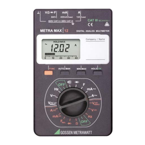
- Page 3 Operating and Connector Elements 1 Connector Jacks 2 LCD Display 3 HOLD/ON: Measurement Value Storage Key / On Switch 4 MIN/MAX: Key for Storage of Minimum or Maximum Value 5 Selector Switch for OFF and Measurement Function Selection 6 AUTO/MAN: Key for Manual Measurement 7 Multifunction Key Display 1 Digital Display with Decimal Point and Polarity Indicator...
-
Page 4: Table Of Contents
Contents Page Safety Features and Precautions ... . . 5 Initial Start-Up ......8 Selecting Measuring Functions and Ranges . -
Page 5: Safety Features And Precautions
Safety Features and Precautions You have selected an instrument which provides you with a high level of safety. This instrument fulfills the requirements of the applicable EU guidelines and national regulations. We confirm this with the CE marking. The relevant declaration of conformity can be obtained from GMC-I Messtechnik GmbH. - Page 6 • All current ranges are equipped with fuses. The maxi- mum allowable voltage for the measuring current circuit (= nominal voltage of the fuse) is equal to 600 V • The device may only be used for measurements of category CAT II 600 V or CAT III 300 V.
- Page 7 Meaning of symbols on the instrument Warning concerning a point of danger (Attention: observe documentation) Earth Continuous, doubled or reinforced insulation Indicates EU conformity This device may not be disposed of with the trash. Further information regarding the WEEE mark can be accessed on the Internet at www.gossenmetrawatt.com by entering the search term ’WEEE’...
-
Page 8: Initial Start-Up
Initial Start-Up Battery The instrument is delivered in operational condition with batteries installed. Please see chapter 15.1, page 23, before initial start-up of your instrument, or after a lengthy period of storage. Switching the Instrument On ➭ Turn the selector switch from the OFF position to the desired measuring range. -
Page 9: Automatic Measuring Range Selection
3.2 Automatic Measuring Range Selection These multimeters are equipped with automatic measuring range selection for all measuring ranges except for the ranges 400 mV and 10 A. Automatic selection is func- tional as soon as the instrument has been switched on. The instrument automatically selects the measuring range in accordance with the applied measuring magnitude, which provides for optimum resolution. -
Page 10: Lcd Display
LCD Display 4.1 Digital Display The digital display shows the measurement value, decimal point and sign. The selected unit of measure and type of current are displayed. A minus sign appears in front of the digits for the measurement of direct magnitudes, if the positive pole of the measurement magnitude is applied to the “”... -
Page 11: Storing Minimum Or Maximum Values "Min/Max" Hold
Storing Minimum or Maximum Values “MIN/MAX” Hold With the MIN/MAX function, you can “hold” either the mini- mum or the maximum measurement value which was present at the measuring instrument input immediately after activation of MIN or MAX. The most important appli- cation is the determination of the minimum or the maxi- mum measurement value in the long-term observation of measurement magnitudes. -
Page 12: Voltage Measurement
Voltage Measurement ➭ Turn the selector switch, depending upon the desired input resistance, to V > 10 M) or V = 400 k). 400k Note! The measuring instrument is provided with the switch position V for electricians, which has 400k an input resistance of approx. -
Page 13: Current Measurement
Current Measurement Attention! First switch off the power supply to the measur- ing circuit or the load component and discharge any capacitors which might be present. ➭ Select function A with the selector switch for currents > 400 mA, or function mA for currents < 400 mA. Switch to the next highest measuring range, or activate auto- matic measuring range selection first for the measure- ment of currents of an unknown magnitude. -
Page 14: Transformers
600V 400mA fused 10A fused 600 V CAT II / 300 V CAT III 9.1 AC Measurement with (Clip-On) Current Transformers 9.1.1 Transformer Output mA/A Attention! If current transformers are used at the secondary side in an open condition, e.g. due to defective or non-connected power cables, a blown device fuse or incorrect connection, dangerously high voltages can occur at the connections. -
Page 15: Continuity Testing And Resistance Measurement
10 Continuity Testing and Resistance Measurement Attention! Be absolutely certain that the device under test is voltage-free. Extraneous voltages distort the measurement results! ➭ Set the selector switch to “ “. ➭ Connect the DUT as shown. 600V 400mA fused 10A fused 600 V CAT II / 300 V CAT III Continuity Testing... -
Page 16: Diode Testing
11 Diode Testing Attention! Be absolutely certain that the device under test is voltage-free. Extraneous voltages distort the measurement results! ➭ Set the selector switch to “ “. ➭ Connect the device under test as shown. Conducting Direction and Short-Circuit The measuring instrument displays the forward voltage in volts. -
Page 17: Capacitance Measurement
12 Capacitance Measurement Attention! Be absolutely certain that the device under test is voltage-free. Extraneous voltages distort the measurement results! ➭ Set the selector switch to “F”. ➭ Connect the (discharged!) device under test to jacks “” and “F” with measurement cables. Polarized capacitors must be connected to the “”... -
Page 18: Frequency Measurement
Delete Zero Balancing ➭ Press and hold the multifunction key and a two-fold acoustic signal acknowledges deletion, ➭ Activate the selector switch ➭ Switch the multimeter off. 13 Frequency Measurement ➭ Set the selector switch to Hz. The frequency measurement mode is activated. Fre- quency is displayed at the LCD. -
Page 19: Characteristic Values
14 Characteristic Values Input Impedance Measuring Measuring 100 pF // X Resolution Function Range 400k 100 V 400.0 mV > 20 M 400 k 4.000 1 mV 11 M 400 k 40.00 10 mV 10 M 400 k 400k 400.0 100 mV 10 M... - Page 20 Digital Display Intrinsic Uncertainty Overload Capacity Measuring Measuring at Reference Conditions Function Range Value Duration (...% of rdg. +... D) 400.0 mV 0.75 + 2 4.000 600 V 40.00 continuous effective 0.5 + 2 400k 400.0 400.0 mV 1.5 + 5 4.000 600 V 40.00...
- Page 21 Reference Conditions Ambient + 23 C 2 K Temperature Relative Humidity 40% ... 60% Measuring Magnitude Frequency Sine, 50 Hz Measuring Magnitude Waveform Sine 3 V 0.1 V Battery Voltage Ambient Conditions Working Temperature 10 C ... + 50 C Range Storage Temperature ...
- Page 22 Influence Variables and Effects Meas. Magnitude/ Influence Variable Influence Range Influence Effect Measuring Range 0 C ... +21 C 0.1 x intrinsic Temperature uncertainty/K +25 C... +40 C Influence Range Inherent Uncertainty at Ref. Influence Variable Frequency (... % of rdg. +... D) (max.
-
Page 23: Maintenance
Fusing Fuse for ranges up to 400 mA FF(UR) 1.6 A / 700 V; 6.3 mmx32 mm; breaking capacity 50 kA at 700 V with resistive load, cos < 0.2; protects all current measuring ranges up to 400 mA in combination with power diodes Fuse for 10 A Range... -
Page 24: Fuses
tery must be installed, before the instrument can be placed back into operation. If the “ “ symbol appears in the LCD display, you should change the battery as soon as possible. You can continue to take measurements, but reduced measuring accuracy may result. -
Page 25: Housing
Attention! Be absolutely certain that only the specified fuses are used! The use of a fuse with different triggering characteristics, a different nominal cur- rent or a different breaking capacity places the operator, the system and the measuring instru- ment in danger. The use of repaired fuses or short-circuiting of the fuse holder is prohibited. -
Page 26: Recalibration
Batteries or rechargeable batteries may contain harmful substances or heavy metal such as lead (PB), cadmium (CD) or mercury (Hg). They symbol shown to the right indicates that bat- teries or rechargeable batteries may not be dis- posed of with the trash, but must be delivered to Pb Cd Hg collection points specially provided for this pur- pose. -
Page 27: Repair And Replacement Parts Service
17 Repair and Replacement Parts Service Calibration Center* and Rental Instrument Service If required please contact: GMC-I Service GmbH Service Center Thomas-Mann-Straße 20 90471 Nürnberg • Germany Phone +49 911 817718-0 Fax +49 911 817718-253 E-Mailservice@gossenmetrawatt.com www.gmci-service.com This address is only valid for Germany. In other countries our representatives or subsidiaries may be contacted. - Page 28 Edited in Germany • Subject to change without notice • A pdf version is available on the internet GMC-I Messtechnik GmbH Südwestpark 15 90449 Nürnberg • Germany Phone +49 911 8602-111 +49 911 8602-777 E-Mail info@gossenmetrawatt.com www.gossenmetrawatt.com...
Need help?
Do you have a question about the METRA MAX 12 and is the answer not in the manual?
Questions and answers