Table of Contents
Advertisement
Quick Links
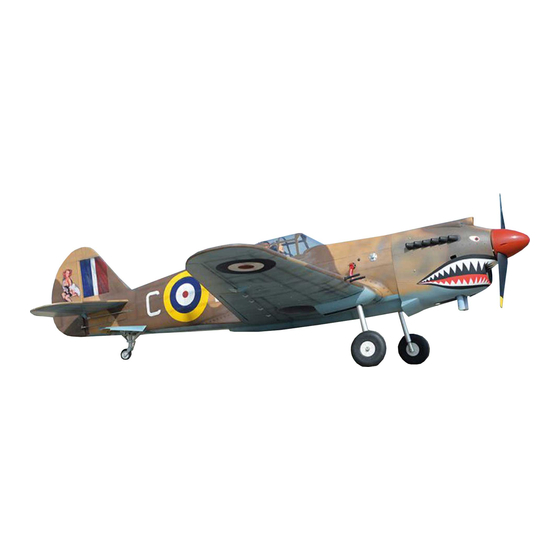
Instruction Manual book
SPECIFICATION
Wingspan :
Length
Weight
Radio
Servo
Engine
1,660 mm
:
1,420 mm
:
3.8 kg
:
06 channels.
:
08 servos.
:
75 Cu.in
91 Cu.in
65.35 in.
55.91 in.
8.36 Lbs.
2 Stroke.
4 Stroke.
Made in Vietnam.
ITEM CODE: BH56.
Advertisement
Table of Contents

Related Manuals for Black Horce Model P-40C TOMAHAWK


Summary of Contents for Black Horce Model P-40C TOMAHAWK
- Page 1 Instruction Manual book ITEM CODE: BH56. SPECIFICATION Wingspan : 1,660 mm 65.35 in. Length 1,420 mm 55.91 in. Weight 3.8 kg 8.36 Lbs. Radio 06 channels.
- Page 2 P-40C TOMAHAWK. This instruction manual is designed to help you build a great flying aeroplane. Please read this manual thoroughly before starting assembly of your P-40C TOMAHAWK. Use the parts listing below to identify all parts. WARNING. Please be aware that this aeroplane is not a toy and if assembled or used incorrectly it is capable of causing injury to people or property.
-
Page 3: Safety Precaution
P-40C TOMAHAWK. Caution: this model is not a toy! SAFETY PRECAUTION. If you are a beginner to this type of powered model, please ask an experienced model flyer + This is not a toy for help and support. If you attempt to operate + Be sure that no other flyers are using your radio frequency. -
Page 4: Installing The Aileron Servos
P-40C TOMAHAWK. INSTALLING THE AILERON SERVOS. 1) Install the rubber grommets and brass eyelets onto the aileron servos. C/A glue Bottom of wing C/A glue C/A glue C/A glue C/A glue... - Page 5 P-40C TOMAHAWK. C/A glue C/A glue R e m o v e covering. C/A glue 3) Using the thread as a guide and using masking tape, tape the servo lead to the end of the thread: carefully pull the thread out.
- Page 6 P-40C TOMAHAWK. Aileron servo tray Thread. Servo wire. 5. Instal servo tray with aileron servo into the wing as same as picture below. 2x10mm. Secure aileron control horn INSTALLING THE AILERON CONTROL HORN. Remove covering 3mm x 40mm. M3 lock nut.
-
Page 7: Installing The Aileron Linkages
P-40C TOMAHAWK. C/A glue INSTALLING THE AILERON LINKAGES. 1. Working with the aileron linkage for now, thread one clevis onto one of the threaded wires. 2. Attach the clevis to the outer hole in the control horn. ... -
Page 8: Installing The Flap Servos
P-40C TOMAHAWK. 4. Locate one nylon servo arm, and using wire cutters,remove all but one of the arms. Using a 2mm drill bit, enlarge the third hole out from the center of the arm to accommo- date the aileron pushrod wire. - Page 9 P-40C TOMAHAWK. INSTALLING THE FLAP CONTROL HORN. 3mm x 40mm. C/A glue M3 lock nut. Nilon control clasp Remove covering...
-
Page 10: Landing Gear
P-40C TOMAHAWK. INSTALLING THE AILERON INSTALLING RETRACTABLE LINKAGES. LANDING GEAR. Remove covering Aileron servo Flap servo Aileron Remove covering Flap Bottom of wing Remove covering on the pre- cut slot as picture. Top of wing... - Page 11 P-40C TOMAHAWK. Secure C/A glue...
- Page 12 P-40C TOMAHAWK. 3 x 12 mm Mark point Secure Drill a hole 2mm diameter Secure...
- Page 13 P-40C TOMAHAWK. Trim and cut the fairings as pictures below. Secure...
-
Page 14: Installing The Engine Mount
P-40C TOMAHAWK. C/A glue INSTALLING THE ENGINE MOUNT. See pictures below: Repeat the procedure for the other wing. -
Page 15: Installing The Stopper Assembly
P-40C TOMAHAWK. C/A glue FUEL TANK. INSTALLING THE STOPPER ASSEMBLY 1) The stopper has been pre-assembled at the factory. 2) Using a modeling knife, cut one length of silicon fuel line (the length of silicon fuel line Drill a hole 3mm... - Page 16 P-40C TOMAHAWK. 8) Feed three lines through the fuel tank compartment and through the pre-drilled hole in the firewall. Pull the lines out from behind the engine, while guiding the fuel tank into place. Push the fuel tank as far forward as possible, the front of the tank should just about touch the back of the firewall.
-
Page 17: Installing The Engine
P-40C TOMAHAWK. Mark point Drill a hole 4mm diameter INSTALLING THE ENGINE. Locate the long piece of wire used for the throttle pushrod. One end of the wire has been pre-bend in to a “Z” bend at the factory. This “Z”... - Page 18 P-40C TOMAHAWK. Trim and cut Pushrod wire. Right side Pushrod wire. Left side 3 x 10mm Machine screw COWLING. 1) Slide the fiberglass cowl over the en- Right side gine and line up the back edge of the cowl with the marks you made on the fuselage.
-
Page 19: Installing The Spinner
P-40C TOMAHAWK. 2) While keeping the back edge of the cowl flush with the marks, align the front of the cowl with the crankshaft of the engine. The front of the cowl should be positioned so the crankshaft is in nearly the middle of the cowl opening. - Page 20 P-40C TOMAHAWK. C/A glue Battery ELEVATOR INSTALLATION. SERVO INSTALLATION. 1. Install the rubber grommets and brass collets into the elevator servo. Test fit the servo into the servo tray. C/A glue 2. Mount the servo to the tray using the mounting screws provided with your radio sys- tem.
- Page 21 P-40C TOMAHAWK. 3) Mark the shape of the vertical on the left and right sides onto the horizontal stabilizer Remove covering. using a left-tip pen. Remove covering Remove covering. 4) Remove the stabilizer. Using the lines you just drew as a guide, carefully remove the covering from between them using a modeling knife.
-
Page 22: Elevator Control Horn Installa- Tion
P-40C TOMAHAWK. Epoxy glue C/A glue 6. After the epoxy has fully cured, re- move the masking tape or T-pins used to 5) When you are sure that everything is hold the stabilizer in place and carefully in- aligned correctly, mix up a generous amount spect the glue joints. -
Page 23: Elevator Pushrod Installation
P-40C TOMAHAWK. C/A glue Top side E l e v a t o r E l e v a t o r cotrol horn cotrol horn ELEVATOR PUSHROD INSTALLATION. Elevator pushrod install as same as the way of aileron pushrod. - Page 24 P-40C TOMAHAWK. Bend and cut after Secure Snap keeper Secure Elevator servo...
-
Page 25: Vertical Stabilizer
P-40C TOMAHAWK. VERTICAL STABILIZER. C/A glue C/A glue C/A glue Hinge. 1) Using a modeling knife, cut away the covering from the end of fuselage for the rud- der hinge. C/A glue Hinge slot 2) Put the rudder into the fuselage as same... - Page 26 P-40C TOMAHAWK. 3) Mark the shape of the vertical on the left Top side and right sides of the rudder using a left-tip pen. Mark line 4. Now, remove the rudder and using a modeling knife, carefully cut just inside the marked lines and remove the film of the rud- der.
- Page 27 P-40C TOMAHAWK. 6) When you are sure that everything is a aligned correctly, mix up a generous amount of 30 minute epoxy. Apply a thin layer to the slot in the mounting platform and to the verti- cal stabilizer mounting area. Apply epoxy to Epoxy glue the lower rudder hinge.
- Page 28 P-40C TOMAHAWK. Remove covering Slot of the rudder pushrod 3 x 12mm Bottom of fuselage Rudder control horn...
- Page 29 P-40C TOMAHAWK. Secure M2 clevis M2 lock nut Rudder pusrod...
- Page 30 P-40C TOMAHAWK. Elevator pushrod Elevator pushrod Rudder pushrod Rudder pushrod Secure Bend and Rudder cut after pushrod Rudder servo C/A glue Elevator servo...
-
Page 31: Installing The Switch
P-40C TOMAHAWK. PUSHROD THROTTLE SERVO INSTALLATION. Install adjustable servo connector in the servo arm. Throttle servo Connector. Servo arm. INSTALLING THE SWITCH. After installing the adjustable metal con- 1) Cut out the switch hole using a modeling nector apply a small drop of thin C/A to the knife. - Page 32 P-40C TOMAHAWK. RETRACTABLE SERVO INSTALLATION. INSTALLING THE RECEIVER Mark point Retract servo 1) Plug the servo leads and the switch lead into the receiver. You may want to plug an aileron extension into the receiver to make plugging in the aileron servo lead easier when you are installing the wing .
-
Page 33: Joining The Wing Halves
P-40C TOMAHAWK. Drill a hole 3mm diameter 3 x 40mm Right wing Receiver Secure JOINING THE WING HALVES. 1) Location the aluminium wing dihedral brace. 2) Test fit the dihedral brace into each wing haft. The brace should slide in easily. If not, use 220 grit sand down the edges and ends of the brace until it fits properly. -
Page 34: Wing Attachment
P-40C TOMAHAWK. Left wing Wing bolt Left wing RETRACTABLE PUSHROD. Secure 2 5 m m WING ATTACHMENT. See picture wing attach to fuselage. C/A glue... - Page 35 P-40C TOMAHAWK. Installing the canopy as same as pic- ture below. Secure C u t Secure...
-
Page 36: Control Throws
P-40C TOMAHAWK. BALANCING. CONTROL THROWS. 1) It is critical that your airplane be bal- 1. We highly recommend setting up a plane anced correctly. Improper balance will cause using the control throws listed. - Page 37 P-40C TOMAHAWK.
- Page 38 P-40C TOMAHAWK.
Need help?
Do you have a question about the P-40C TOMAHAWK and is the answer not in the manual?
Questions and answers