Table of Contents
Advertisement
Quick Links
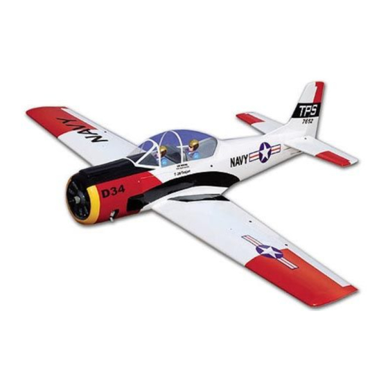
INSTRUCTION MANUAL BOOK.
SPECIFICATION
Wingspan
Length
Weight
Parts listing required(not included):
Radio
Servo
Motor
Battery: 3 CELLS - LI - POL Y - 1 1.1v - 3500 mA.h.
Engine:
:
1,250 mm
:
1,040 mm
:
1.75 kg
:
04 channel.
:
04 - 05 servos.
:
AXI2826.10.
25 - 32 Cu.in
49.21 in.
40.94 in.
3.85 Lbs.
2 S troke
Made in Vietnam.
Advertisement
Table of Contents

Related Manuals for Black Horce Model T28-TROJAN BH .43


Summary of Contents for Black Horce Model T28-TROJAN BH .43
- Page 1 INSTRUCTION MANUAL BOOK. SPECIFICATION Wingspan 1,250 mm 49.21 in. Length 1,040 mm 40.94 in. Weight 1.75 kg 3.85 Lbs. Parts listing required(not included): Radio 04 channel. Servo 04 - 05 servos. Motor AXI2826.10. Battery: 3 CELLS - LI - POL Y - 1 1.1v - 3500 mA.h. Engine: 25 - 32 Cu.in 2 S troke...
- Page 2 TROJAN. Instruction Manual This instruction manual is designed to help you build a great flying aeroplane. Please read this manual thoroughly before starting assembly of your TROJAN. Use the parts listing below to identify all parts. WARNING. Please be aware that this aeroplane is not a toy and if assembled or used incorrectly it is capable of causing injury to people or property.
-
Page 3: Safety Precaution
TROJAN. INSTRUCTION MANUAL INSTALLING THE AILERON SERVOS. SAFETY PRECAUTION. 1. Install the rubber grommets and brass + This is not a toy eyelets onto the aileron servo. + Be sure that no other flyers are using your radio frequency. + Do not smoke near fuel + Store fuel in a cool, dry place, away from children and pets. -
Page 4: Instruction Manual
TROJAN. Instruction Manual 3) Using the thread as a guide and using masking tape, tape the servo lead to the end of the thread: carefully pull the thread out. When you have pulled the servo lead out, re- move the masking tape and the servo lead from the thread. - Page 5 TROJAN. INSTRUCTION MANUAL INSTALLING THE AILERON CONTROL HORN. Nilon M3 lock nut control clasp. 3mm x 30mm. Control horn of Aileron Install control horn as same as picture be- low. Install aileron control horn as same as pic- ture below. Aileron Control horn C/A glue Remove...
-
Page 6: Installing The Aileron Linkages
TROJAN. Instruction Manual 5. Using pliers, carefully make a 90 degree bend down at the mark made. Cut off the excess wire, leaving about 4mm beyond the bend. Control horn Aileron Repeat the procedure for the other wing half. INSTALLING THE AILERON LINKAGES. -
Page 7: Installing Landing Gear
TROJAN. INSTRUCTION MANUAL Mark point Repeat the procedure for the other wing half. INSTALLING LANDING GEAR. See pictures below: 2x10mm. Remove covering. Secure... -
Page 8: Joining The Wing Halves
TROJAN. Instruction Manual Repeat the procedure for the other gear. JOINING THE WING HALVES. 1. Using a modeling knife, remove the cov- ering wing. Plastic strap Remove covering. Top side C/A glue 2. Location the aluminium wing dihedral brace. Plastic leg cover 3. - Page 9 TROJAN. INSTRUCTION MANUAL Bottom side Top side THERE ARE TWO OPTIONS: 1. ELECTRIC MOTOR 2. ENGINE MOUNT. OPTION 1: ELECTRIC MOTOR INSTALLING ELECTRIC MOTOR. Wing bolt plate 3x 10mm. Remove covering...
-
Page 10: Installing The Receiver And Battery
TROJAN. Instruction Manual Front view. INSTALLING THE RECEIVER AND BATTERY. 1) Plug the servo leads and the switch lead into the receiver . You may want to plug an aileron extension into the receiver to make plugging in the aileron servo lead easier when you are installing the wing . -
Page 11: Installing The Nose Gear
TROJAN. INSTRUCTION MANUAL Battery. INSTALLING THE NOSE GEAR. COWLING. 1) Slide the cowl over the motor and line up the back edge of the cowl with the marks you made on the fuselage. -
Page 12: Installing The Engine Mount
TROJAN. Instruction Manual 2) While keeping the back edge of the OPTION 2: ENGINE MOUNT. cowl flush with the marks, align the front of the cowl with the crankshaf t of the motor . The INSTALLING THE ENGINE MOUNT. front of the cowl should be positioned so the crankshaft is in nearly the middle of the cowl opening. -
Page 13: Installing The Stopper Assembly
TROJAN. INSTRUCTION MANUAL FUEL TANK. INSTALLING THE STOPPER ASSEMBLY 1. The stopper has been pre-assembled at the factory. 2. Using a modeling knife, cut one length of silicon fuel line (the length of silicon fuel line is calculated by how the weighted clunk should rest about 8mm away from the rear of the tank and move freely inside the tank). -
Page 14: Installing The Engine
TROJAN. Instruction Manual C/A glue Fuel tank. INSTALLING THE ENGINE. Locate the long piece of wire used for the throttle pushrod. One end of the wire has been pre-bend in to a “Z” bend at the factory . This “Z” bend should be inserted into the throttle arm of the engine when the engine is fitted onto the engine mount. - Page 15 TROJAN. INSTRUCTION MANUAL Pushrod wire. COWLING. 1. Slide the fiberglass cowl over the en- gine and line up the back edge of the cowl with the marks you made on the fuselage.
-
Page 16: Elevator Installation
TROJAN. Instruction Manual 2. While keeping the back edge of the cowl flush with the marks, align the front of the cowl with the crankshaft of the engine. The front of the cowl should be positioned so the crankshaft is in nearly the middle of the cowl opening. -
Page 17: Horizontal Stabilizer Installation
TROJAN. INSTRUCTION MANUAL 3. Mark the shape of the vertical on the left HORIZONTAL STABILIZER and right sides onto the horizontal stabilizer INSTALLATION. using a felt-tip pen 1. Using a modeling knife, cut away the covering from the fuselage for the stabilizer and remove it. -
Page 18: Elevator Control Horn Installa- Tion
TROJAN. Instruction Manual C/A glue. Expoxy glue. 5. When you are sure that everything is aligned correctly, mix up a generous amount of 30 minute epoxy. Apply a thin layer to the top and bottom of the stabilizer mounting area and to the stabilizer mounting platform sides in the fuselage. -
Page 19: Elevator Pushrod Installation
TROJAN. INSTRUCTION MANUAL C/A glue Elevator control horn. ELEVATOR PUSHROD INSTALLATION. Pushrod install as same as method of pushrod wing. See pictures below:... - Page 20 TROJAN. Instruction Manual Elevator servo. Elevator Pushrod Bend and cut after. Secure...
-
Page 21: Vertical Installation
TROJAN. INSTRUCTION MANUAL C/A glue C/A glue Snap keeper. VERTICAL INSTALLATION. C/A glue Rudder servo. Elevator servo. Hinge. - Page 22 TROJAN. Instruction Manual 1) Using a modeling knife, remove the covering from the top of the fuselage and the covering from over the precut hinge slot cut into the lower rear portion of the fuselage This slot accepts the lower vertical. Mark point 4.
-
Page 23: Rudder Control Horn Installation
TROJAN. INSTRUCTION MANUAL RUDDER CONTROL HORN INSTALLATION. Vertical Stabilizer. Rudder control horn install as same as the Horizontal 90º Stabilizer. way of aileron control horn. Please see pictures below. Epoxy glue. C/A glue C/A glue 6) When you are sure that everything is a aligned correctly, mix up a generous amount of 30 minute epoxy. -
Page 24: Rudder Pushrod Installation
TROJAN. Instruction Manual RUDDER PUSHROD INSTALLATION. Rudder pushrod install as same as the way of aileron pushrod. Bend and cut after. Secure Rudder Rudder pushrod pushrod... -
Page 25: Installing The Switch
TROJAN. INSTRUCTION MANUAL Secure Nose gear pushrod Rudder pushrod Throttle pushrod INSTALLING THE SWITCH. 1. Cut out the switch hole using a modeling knife. Use a 2mm drill bit and drill out the two mounting holes through the fuselage side. INSTALLING THE THROTTLE PUSHROD. - Page 26 TROJAN. Instruction Manual 3. Position the battery pack and receiver behind the fuel tank. Use two tie wraps to hold the battery and receiver securely in place as pictures below Do not permanently secure the receiver and battery until after balancing the model. 4.
-
Page 27: Wing Attachment
TROJAN. INSTRUCTION MANUAL Installing the fuselage hatch as same as pic- ture below. Receiver WING ATTACHMENT. See picture wing attach to fuselage. - Page 28 TROJAN. Instruction Manual BALANCING. 1) It is critical that your airplane be bal- anced correctly. Improper balance will cause your plane to lose control and crash. THE CENTER OF GRA VITY IS LOCA TED 70mm BACK FROM THE LEADING EDGE OF THE WING.
-
Page 29: Control Throws
TROJAN. INSTRUCTION MANUAL CONTROL THROWS. 1. We highly recommend setting up a plane using the control throws listed. 2. The control throws should be measured at the widest point of each control surface. 3. Check to be sure the control surfaces move in the correct directions.
Need help?
Do you have a question about the T28-TROJAN BH .43 and is the answer not in the manual?
Questions and answers