Table of Contents
Advertisement
Quick Links
Advertisement
Table of Contents

Related Manuals for Black Horce Model EDGE BH 69


Summary of Contents for Black Horce Model EDGE BH 69
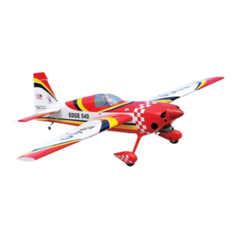
- Page 1 Instruction Manual book SPECIFICATION Wingspan : 1,580 mm 62.20 in. Length 1,400 mm 55.12 in. Weight 3.6 kg 7.26 Lbs. Radio 06 channels.
-
Page 2: Instruction Manual
EDGE - Instruction Manual Item code: BH69-A . This instruction manual is designed to help you build a great flying aeroplane. Please read this manual thoroughly before starting assembly of your EDGE. Use the parts listing below to identify all parts. WARNING. -
Page 3: Safety Precaution
EDGE - Instruction Manual Item code: BH69-A . Caution: this model is not a toy! If you are a beginner to this type of powered model, please ask an experienced model flyer for help and support. If you attempt to operate the model without knowing what you are doing you could easily injure yourself or somebody else. - Page 4 EDGE - Instruction Manual Item code: BH69-A . REPLACEMENT LARGE PARTS A. Cowling. B. Wing panel. C. Fuselage. D . Horizontal stabilizer. E. Rudder F. Aluminium wing dihedral brace. G. Decal sheet. K.Pilot. REPLACEMENT SMALL PARTS 5x40mm 4x30mm 1. Aluminium landing gear. 5.
-
Page 5: Installing The Aileron Servos
EDGE - Instruction Manual Item code: BH69-A . Temporary pin to keep hinge centered. Assemble then apply drops of thin I. AILERON. C/A to center of hinge,on both sides. 1.INSTALLING THE AILERON SERVOS. 1) Install the rubber grommets and brass ... - Page 6 EDGE - Instruction Manual Item code: BH69-A . Drill a hole 1.5mm diameter 2 x 10 mm. Secure. Secure. Repeat the procedure for the other wing 3) Using the thread as a guide and using half. masking tape, tape the servo lead to the end of the thread: carefully pull the thread out.
-
Page 7: Installing The Aileron Linkages
EDGE - Instruction Manual Item code: BH69-A . INSTALLING THE AILERON LINKAGES. 1. Working with the aileron linkage for now , thread one clevis onto one of the threaded wires. 2. Attach the clevis to the outer hole in the ... -
Page 8: Installing The Engine Mount
EDGE - Instruction Manual Item code: BH69-A . Secure. Drill a hole 5mm diameter Bottom side. Repeat the procedure for the other wing half. INSTALLING THE ENGINE MOUNT. See pictures below: 4 x 30mm 4 x 30mm FUEL TANK. INSTALLING THE STOPPER ASSEMBLY Silicon tube not included... - Page 9 EDGE - Instruction Manual Item code: BH69-A . 1. The stopper has been pre-assembled at Blow through one of the lines to ensure the factory. the fuel lines have not become kinked inside the fuel t ank comp artment. Air should flow 2.
-
Page 10: Installing The Engine
EDGE - Instruction Manual Item code: BH69-A . INSTALLING THE ENGINE. Locate the long piece of wire used for the 4 x 30mm throttle pushrod. One end of the wire has been pre-bend in to a “Z” bend at the factory . This “Z”... - Page 11 EDGE - Instruction Manual Item code: BH69-A . Left side Right side Trim and cut. Right side. 3. Slide the cowl back over the engine and secure it in place using four wood screws. See picture below. 4. Install the muffler and muffler extension onto the engine and make the cutout in the cowl for muffler clearance.
-
Page 12: Installing The Spinner
EDGE - Instruction Manual Item code: BH69-A . INSTALLING THE THROTTLE PUSHROD. Right side. Install one adjustable metal connector through the third hole out from the center of Secure. one servo arm, enlarge the hole in the servo arm using a 2mm drill bit to accommodate the servo connector. - Page 13 EDGE - Instruction Manual Item code: BH69-A . Secure. Cut. Elevator servo. HORIZONTAL STABILIZER INSTALLATION. Horizontal stabilize installation . See picture below. Top side Throttle pushrod ELEVATOR INSTALLATION. SERVO INSTALLATION. 1. Install the rubber grommets and brass Cut the covering collets into the elevator servo.
-
Page 14: Elevator Control Horn Installation
EDGE - Instruction Manual Item code: BH69-A . Top side Drill a hole 1.5mm ELEVATOR CONTROL HORN INSTALLATION. Elevator control horn install as same as the way of aileron control horn. Please see pic- 1. Draw a center line onto the horizontal ... - Page 15 EDGE - Instruction Manual Item code: BH69-A . Top side Mark line. 5. When you are sure that everything is aligned correctly, mix up a generous amount of 30 minute epoxy. Apply a thin layer to the top and bottom of the stabilizer mounting area and to the stabilizer mounting platform sides in the fuselage.
-
Page 16: Elevator Pushrod Installation
EDGE - Instruction Manual Item code: BH69-A . Elevator pushrod Cut. C/A glue. ELEVATOR PUSHROD INSTALLATION. Elevator pushrod install as same as the way of aileron pushrod. M2 lock nut Elevator pushrod E l e v a t o r Elevator pushrod pushrod. -
Page 17: Rudder Servo Installation
EDGE - Instruction Manual Item code: BH69-A . Control horn of Rudder . Secure Elevator pushrod. RUDDER SERVO INSTALLATION. Rudder servo install as same as method of elevator servo. See picture below: A+B Epoxy PLUS glue. Rudder servo Rudder control horn. Secure Drill a hole 1.5mm. -
Page 18: Rudder Pushrod Installation
EDGE - Instruction Manual Item code: BH69-A . RUDDER PUSHROD INSTALLATION. 1. Rudder pushrod install as same as the way of aileron control horn. Cut the covering away from the slot. Temporary pin to keep hinge centered. Rudder Pushrod Bend Assemble then apply drops of thin C/A to center of hinge,on both sides. -
Page 19: Mounting The Tail Wheel Bracket
EDGE - Instruction Manual Item code: BH69-A . 2. Using a pen, mark the locations of the two mounting screws. Remove the tail wheel bracket and drill 1mm pilot holes at the loca- tions marked. R u d d e r pushrod. - Page 20 EDGE - Instruction Manual Item code: BH69-A . MAIN GEAR INSTALATION. PARTS REQUIRED Secure. 5x40mm 3. Using the hardware provided, mount the main landing gear to the fuselage. Cut. 1) The blind nuts are already mounted in- side the fuselage. ...
- Page 21 EDGE - Instruction Manual Item code: BH69-A . C/A glue. 1) Assemble and mounting the wheel p ants as shown in the following pictures. Mark line. 5x40mm Drill a hole Remove covering. Secure.
-
Page 22: Installing The Switch
EDGE - Instruction Manual Item code: BH69-A . 3. Position the battery pack and receiver behind the fuel tank. Use the two light plywood pieces, placed over the battery and receiver and glue to the fuselage sides to hold the bat- tery and receiver securely in place. -
Page 23: Installing Cockpit Fuselage
EDGE - Instruction Manual Item code: BH69-A . *** Test fit the aluminium tube dihedral brace into each wing haft. The brace should slide in Secure easily. If not, use 220 grit sand around the edges and ends of the brace until it fits prop- erly. - Page 24 EDGE - Instruction Manual Item code: BH69-A . BALANCING. 1) It is critical that your airplane be bal- anced correctly. Improper balance will cause your plane to lose control and crash. THE CENTER OF GRAVITY IS LOCATED 75MM BACK FROM THE LEADING EDGE OF THE WING.
-
Page 25: Control Throws
EDGE - Instruction Manual Item code: BH69-A . CONTROL THROWS. PRE-FLIGHT CHECK. 1) We highly recommend setting up a 1) Completely charge your transmitter and plane using the control throws listed. receiver batteries before your first day of fly- ing.
Need help?
Do you have a question about the EDGE BH 69 and is the answer not in the manual?
Questions and answers