
Related Manuals for Black Horce Model Sedona


Summary of Contents for Black Horce Model Sedona
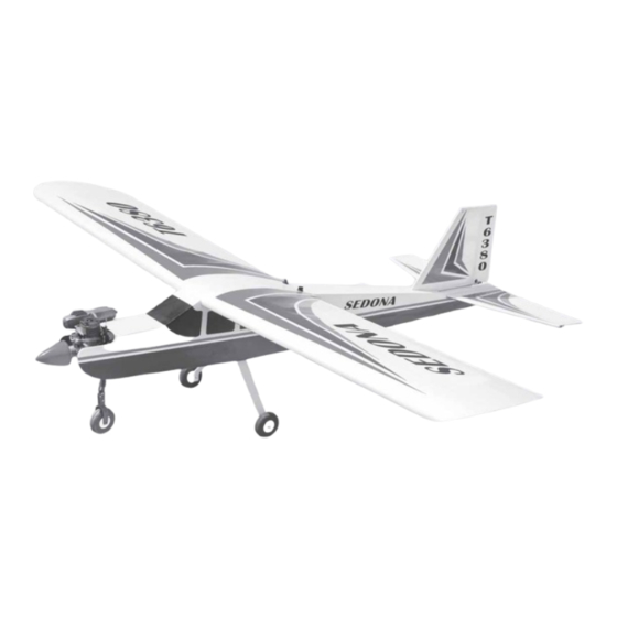
- Page 1 Instruction Manual book SPECIFICATION Wingspan : 1,800 mm 70.87 in. Length 1,470 mm 57.87 in. Weight 2.6 kg 5.72 Lbs. Radio 04 channels. Servo 04 -5 servos. Engine 46 - 55 2 stroke. Made in Vietnam.
-
Page 2: Instruction Manual
Instruction Manual ITEM CODE: BH68. This instruction manual is designed to help you build a great flying aeroplane. Please read this manual thoroughly before starting assembly of your SEDONA. Use the parts listing below to identify all parts. WARNING. Please be aware that this aeroplane is not a toy and if assembled or used incorrectly it is capable of causing injury to people or property. -
Page 3: Safety Precaution
SEDONA - INSTRUCTION MANUAL ITEM CODE:BH68. INSTALLING THE AILERON SERVOS. SAFETY PRECAUTION. 1) Install the rubber grommets and brass + This is not a toy eyelets onto the aileron servo. + Be sure that no other flyers are using your radio frequency. - Page 4 SEDONA - Instruction Manual ITEM CODE: BH68. 5) Using Kwik Bond 5 Minute Epoxy, glue the servo mount into place. Remove any ex- cess epoxy using a paper towel and rubbing alcohol. Use pieces of masking tape to hold the tray in place until the epoxy fully cures.
-
Page 5: Wing Assembly
SEDONA - INSTRUCTION MANUAL ITEM CODE:BH68. WING ASSEMBLY. 1) Location the aluminium wing dihedral brace. 2) Test fit the dihedral brace into each wing half. The brace should slide in easily. If not, use 220 grit sandpaper with a sanding block and sand down the edges and ends of the brace until it fits properly. -
Page 6: Installing The Aileron Linkage
SEDONA - Instruction Manual ITEM CODE: BH68. Bend and cut after Masking tape. INSTALLING THE AILERON LINKAGE. Snap keeper Nilon control claps 1) Thread one nylon adjustable control horn onto each aileron torque rod. Thread the horns on until they are flush with the ends of the torque rods. -
Page 7: Installing The Engine Mount
SEDONA - INSTRUCTION MANUAL ITEM CODE:BH68. When the stopper assembly is installed INSTALLING THE ENGINE MOUNT. in the tank, the top of the vent tube should rest just below the top surface of the tank. It should not touch the top of the tank. -
Page 8: Installing The Engine
SEDONA - Instruction Manual ITEM CODE: BH68. 8) Feed three lines through the fuel tank compartment and through the pre-drilled hole in the firewall. Pull the lines out from behind the engine, while guiding the fuel tank into place. Push the fuel tank as far forward as possible, the front of the tank should just about touch the back of the firewall. -
Page 9: Nose Gear Installation
SEDONA - INSTRUCTION MANUAL ITEM CODE:BH68. Installing steering arm as follow Adjust the nose gear steering arm until the arm is parallel with the fire wall. Drill a hole 2mm. 3 x 20mm Secure Steering arm NOSE GEAR INSTALLATION. Steering arm. -
Page 10: Installing The Main Landing Gear
SEDONA - Instruction Manual ITEM CODE: BH68. INSTALLING THE MAIN LANDING GEAR. 1. The blind nuts are already mounted Secure inside the fuselage. 2. The holes in the landing gear should be to accept the mounting bolts. 3. Using the hardware provided, mount the main landing gear to the fuselage. -
Page 11: Installing The Throttle Pushrod
SEDONA - INSTRUCTION MANUAL ITEM CODE:BH68. INSTALLING THE THROTTLE PUSHROD. See pictures below: Throttle pushrod Install one adjustable metal connector through the third hole out from the center of one servo arm, enlarge the hole in the servo arm using a 2mm drill bit to accommodate the servo connector. - Page 12 SEDONA - Instruction Manual ITEM CODE: BH68. Tracing a line with your finger and using a modeling knife, carefully remove the covering as picture below. Remove covering Remove covering Epoxy glue Mark line C/A glue. When cutting through the covering to re- move it, cut with only enough pressure to only cut through the covering itself.
- Page 13 SEDONA - INSTRUCTION MANUAL ITEM CODE:BH68. ELEVATOR CONTROL HORN AND - ELEVATOR PUSHROD INSTALLATION. Elevator control horn install as same as the way of aileron control horn. Please see pic- tures below. Nilon control clasp 3 x 35mm M3 lock nut.
-
Page 14: Vertical Installation
SEDONA - Instruction Manual ITEM CODE: BH68. VERTICAL INSTALLATION. Rudder servo install as same as method of elevator servo. See picture below: Top elevator Remove covering Elevator servo Elevator pushrod... -
Page 15: Rudder Control Horn Installa- Tion
SEDONA - INSTRUCTION MANUAL ITEM CODE:BH68. Vertical Stabilizer. Horizontal 90º Stabilizer. Mark line When you are sure that everything is aligned correctly, mix up a generous amount of Flash 30 Minute Epoxy. Apply a thin layer to the mounting slot in the top of the fuselage and to... - Page 16 SEDONA - Instruction Manual ITEM CODE: BH68. Rudder pushrod RUDDER CONTROL HORN INSTALLA- TION. Rudder control horn install as same as the way of aileron control horn. Please see pic- tures below. Nilon control clasp 3 x 35mm M3 lock nut.
-
Page 17: Installing The Switch
SEDONA - INSTRUCTION MANUAL ITEM CODE:BH68. INSTALLING THE SWITCH. 1. Cut out the switch hole using a modeling knife. Use a 2mm drill bit and drill out the two mounting holes through the fuselage side. 2. Secure the switch in place using the two machine screws provided with the radio system. -
Page 18: Wing Attachment
SEDONA - Instruction Manual ITEM CODE: BH68. Wing bolt plate Battery Wing bolt. Receiver Mark point Top side Top side Insert and secure WING ATTACHMENT. See picture wing attach to fuselage. Installing the fuselage hatch as same as pic- ture below. -
Page 19: Control Throws
SEDONA - INSTRUCTION MANUAL ITEM CODE:BH68. *If possible, first attempt to balance the model by changing the position of the receiver bat- tery and receiver. If you are unable to obtain good balance by doing so, then it will be nec-... -
Page 20: Pre-Flight Check
4. Check the control surface. 5. Check the receiver antenna . It should be fully extended and not coiled up inside the fuselage. 6. Properly balance the propeller. We wish you many safe and enjoy- able flights with your SEDONA.
Need help?
Do you have a question about the Sedona and is the answer not in the manual?
Questions and answers