Table of Contents
Advertisement
Quick Links
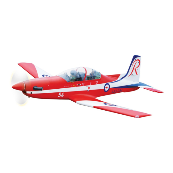
PILATUS PC-9
ALL BALSA - PLY WOOD CONSTRUCTION.
COVERED WITH ORACOVER.
95% ALMOST READY TO FLY
SPECIFICATION
Wingspan: 2,000mm (78.74in).
Length: 2,015mm (79.33in).
Weight: 7.8 kg (17.16 lbs).
Wing area: 64.4dm
Wing loading: 121g/dm
Wing type: NACA airfoils.
Spinner: 90mm.
Gear type: Air retract gear
CNC Suspension Metal Struts (included).
Instruction Manual Book
Parts listing required (Not included).
Engine: O.S GT 33 cc Gas.
Radio: 08 channels.
Servo: 07 servos size (40 x 20 x 38)mm;
.
2
2
Item code: BH151.
+ 3 servos size (32x16x33)mm elevator, rudder.
Standard high torque servos.
Made in Vietnam.
Advertisement
Table of Contents

Related Manuals for Black Horce Model PILATUS PC-9


Summary of Contents for Black Horce Model PILATUS PC-9
- Page 1 Instruction Manual Book Item code: BH151. PILATUS PC-9 ALL BALSA - PLY WOOD CONSTRUCTION. COVERED WITH ORACOVER. 95% ALMOST READY TO FLY SPECIFICATION Parts listing required (Not included). Wingspan: 2,000mm (78.74in). Engine: O.S GT 33 cc Gas. Length: 2,015mm (79.33in).
-
Page 2: Tools And Supplies Needed
PC-9 Item code: BH151. Instruction Manual This instruction manual is designed to help you build a great flying aeroplane. Please read this manual thoroughly PC-9 before starting assembly of your . Use the parts listing below to identify all parts. WARNING Please be aware that this aeroplane is not a toy and if assembled or used incorrectly it is capable of causing injury to people or property. -
Page 3: Safety Precaution
PC-9 Item code: BH151. Instruction Manual Caution: This model is not a toy! SAFETY PRECAUTION If you are a beginner to this type of powered model, + This is not a toy. please ask an experienced model flyer for help and + Be sure that no other flyers are using your radio support. - Page 4 PC-9 Item code: BH151. Instruction Manual REPLACEMENT LARGE PARTS A: Fuselage. B: Wing panel (B1, B2). C: Horizontal stabilizer(C1, C2). D: Rudder. E1: Aluminium wing dihedral brace. E2: Aluminium tube horizontal stabilizer. Pilot. Cowling. G: Decal sheet. M: Cockpit-top hatch. N: Canopy clear.
-
Page 5: Installing The Aileron Servos
PC-9 Item code: BH151. Instruction Manual 3) Using the thread as a guide and using mask- I. AILERON ing tape, tape the servo lead to the end of the thread: carefully pull the thread out. When you have pulled the servo lead out, remove the masking tape and the servo Bottom side. -
Page 6: Installing The Aileron Linkages
PC-9 Item code: BH151. Instruction Manual II. FLAP Repeat step #1- #3 on the part I (page 5,6) to install the flap. 2. Push in Aileron control horn 1. A+B Epoxy glue 3) Repeat the procedure to install the control horn on the opposite aileron. -
Page 7: Installing The Engine Mount
PC-9 Item code: BH151. Instruction Manual Install the tube to the air retract. Collar 5 x 35 mm Secure Air tube Drill a hole Repeat the procedure to install the opposite wing. 2mm diameter Bottom side Place the retract to the wing and pull out the air tube through the wing section. -
Page 8: Installing The Throttle - Cable
PC-9 Item code: BH151. Instruction Manual INSTALLING THE THROTTLE - CABLE Be sure to equip Not included. air vent pipe. Tygon tubing (Gas). And silicone tubing (Methanol). Install one adjustable metal connector through the third hole out from the center of one servo arm, enlarge the To carburetor hole in the servo arm using a 2mm drill bit to accommo- fuel inlet... - Page 9 PC-9 Item code: BH151. Instruction Manual 1) Slide the fiberglass cowl over the engine and line up the back edge of the cowl with the marks you made on the fuselage. 2. Push in Tie wrap. 1. Trim and cut ...
-
Page 10: Installing The Spinner
PC-9 Item code: BH151. Instruction Manual 3. ELEVATOR PUSHROD INSTALLATION VII. INSTALLING THE SPINNER Elevator pushrod install as same as the way of aileron Install the spinner backplate, propeller and spinner pushrod. cone. The spinner cone is held in place using two 3mm x 8mm machine screws. -
Page 11: Rudder Control Horn Installation
PC-9 Item code: BH151. Instruction Manual IX. RUDDER INSTALLATION See pictures below: Aluminium 1. Push in Aluminium tube 9mm. 117 mm Fuselage 2. Push in bottom side Push in Attach the stabilizer to the fuselage. 1.Push in RUDDER CONTROL HORN INSTALLATION 2.Push in Rudder servo and control horn install as same as the way of aileron. - Page 12 PC-9 Item code: BH151. Instruction Manual A+B Epoxy glue 3 way conector 4 way conector Valve one way Valve control Air line sets Connector X. INSTALLING THE AIR TANK Air supply Air tank Please see pictures below. Nose Left main gear gear wing Tie wrap...
- Page 13 PC-9 Item code: BH151. Instruction Manual Secure the connector Push-pull cable nose gear XII. INSTALLING NOSE INSTALLING NOSE GEAR SERVO AIR RETRACTABLE LANDING GEAR Please see pictures below. Nose gear servo Valve control servo Nose air retractable landing gear install as same as the way of air retractable landing gear on the part Throttle servo III (see page 6,7).
- Page 14 PC-9 Item code: BH151. Instruction Manual...
-
Page 15: Installing The Switch
PC-9 Item code: BH151. Instruction Manual XIII. INSTALLING THE SWITCH Battery receiver. Battery of engine. 1) Cut out the switch hole using a modeling knife. Use a 2mm drill bit and drill out the two mounting holes through the fuselage side. ... - Page 16 PC-9 Item code: BH151. Instruction Manual Push in 2. Push in 1. A/B Epoxy glue. Push in Use glue to secure the canopy to the fuselage. The shape of the canopy, so make sure to install it in the correct direction. C/A glue.
-
Page 17: Control Throws
PC-9 Item code: BH151. Instruction Manual BALANCING CONTROL THROWS 1) It is critical that your airplane be balanced cor 1) We highly recommend setting up a plane using rectly. Improper balance will cause your plane to lose the control throws listed. control and crash. - Page 18 I/C FLINGT WARNINGS Always operate in open areas, away adjust the engine from ALWAYS from factories, hospitals, schools, NEVER fly near power lines, behind the propeller, and do not buildings and houses etc. NEVER aerials or other dangerous areas allow any part of your body to be in fly your aircraft close to people or including airports, motorways etc.
Need help?
Do you have a question about the PILATUS PC-9 and is the answer not in the manual?
Questions and answers
pc9 control throw adjustments