Table of Contents
Advertisement
Quick Links
Advertisement
Table of Contents

Related Manuals for Black Horce Model extra 330l


Summary of Contents for Black Horce Model extra 330l
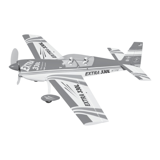
- Page 1 Instruction Manual book ITEM CODE: BH60. SPECIFICATION Wingspan : 1,650mm 64.96 in. Length 1,460mm 57.48 in. Weight 3.8kg 8.38 Lbs. Radio 05 channels.
-
Page 2: Instruction Manual
EXTRA 330L Instruction Manual This instruction manual is designed to help you build a great flying aeroplane. Please read this manual thoroughly before starting assembly of your EXTRA 330L Use the parts listing below to identify all parts. WARNING Please be aware that this aeroplane is not a toy and if assembled or used incorrectly it is capable of causing injury to people or property. -
Page 3: Safety Precaution
EXTRA 330L. INSTRUCTION MANUAL Caution: this model is not a toy! SAFETY PRECAUTION. If you are a beginner to this type of powered + This is not a toy model, please ask an experienced model flyer + Be sure that no other flyers are using your for help and support. -
Page 4: Installing The Aileron Servos
EXTRA 330L Instruction Manual INSTALLING THE AILERON SERVOS. 1. Install the rubber grommets and brass eyelets onto the aileron servo. C/A glue 2. Using a modeling knife, remove the cov- ering servo tray. C/A glue Remove covering C/A glue ... - Page 5 EXTRA 330L. INSTRUCTION MANUAL 4. Drill 1,5mm pilot holes through the block of wood for each of the four mounting screws provided with the servo. Install servo into ai- leron servo tray as same as picture below. Electric wire...
-
Page 6: Installing The Aileron Linkages
EXTRA 330L Instruction Manual INSTALLING THE AILERON LINKAGES. Installing the aileron linkages as pictures below. M3 lock nut Repeat the procedure for the other wing half. INSTALLING THE ENGINE MOUNT. See pictures below: Repeat the procedure for the other wing... -
Page 7: Engine Mount
EXTRA 330L. INSTRUCTION MANUAL ENGINE MOUNT. 4x30mm 4x30mm C/A glue FUEL TANK. INSTALLING THE STOPPER ASSEMBLY Silicon not included. Fuel pick- up tube Vent tube Fuel fill tube Drill a hole 4mm diameter... - Page 8 EXTRA 330L Instruction Manual 1. The stopper has been pre-assembled at 6. When satisfied with the alignment of the the factory. stopper assembly tighten the 3mm x 20mm machine screw until the rubber stopper ex- 2. Using a modeling knife, cut one length of pands and seals the tank opening.
-
Page 9: Installing The Engine
EXTRA 330L. INSTRUCTION MANUAL Mark point Drill a hole 4mm diameter Fuel tank INSTALLING THE ENGINE. Locate the long piece of wire used for the throttle pushrod. One end of the wire has been pre-bend in to a “Z” bend at the factory. This “Z”... - Page 10 EXTRA 330L Instruction Manual Pushrod wire Right side 4 x 30mm Left side Secure COWLING. 1. Slide the fiberglass cowl over the en- gine and line up the back edge of the cowl with the marks you made on the fuselage.
-
Page 11: Installing The Spinner
EXTRA 330L. INSTRUCTION MANUAL Bottom side Right side 2. While keeping the back edge of the cowl flush with the marks, align the front of the cowl with the crankshaft of the engine. The front of the cowl should be positioned so the crankshaft is in nearly the middle of the cowl opening. -
Page 12: Installing The Throttle Pushrod
EXTRA 330L Instruction Manual Secure INSTALLING THE THROTTLE PUSHROD. 1. Install one adjustable metal connector through the third hole out from the center of one servo arm, enlarge the hole in the servo arm using a 2mm drill bit to accommodate the servo connector. -
Page 13: Horizontal Stabilizer
EXTRA 330L. INSTRUCTION MANUAL C/A glue HORIZONTAL STABILIZER. See pictures below: 1) Using a modeling knife, cut away the Top side covering from the fuselage for the stabilizer and remove it. Remove covering. C/A glue 2. Draw a center line onto the horizontal ... - Page 14 EXTRA 330L Instruction Manual Check to mark sure the wing and stabi- lizer are paralell. If they are not, lightly sand the opening in the fuselage for the stabilizer until the stabilizer is paralell to the wing. Mark point Bottom side ...
-
Page 15: Elevator Control Horn Installa- Tion
EXTRA 330L. INSTRUCTION MANUAL C/A glue Bottom side ELEVATOR CONTROL HORN INSTALLA- TION. Elevator control horn install as same as the way of aileron control horn. Please see pic- tures below. 3 x 50mm. M3 lock nut. Nilon control clasp. - Page 16 EXTRA 330L Instruction Manual Elevator pushrod Elevator Elevator Secure pushrod pushrod Bottom side Bend and cut after Top side Secure...
-
Page 17: Vertical Installation
EXTRA 330L. INSTRUCTION MANUAL C/A glue Elevator pushrod Elevator servo VERTICAL INSTALLATION. C/A glue Vertical stabilizer installation See picture below. 1. Using a modeling knife cut away the covering from the end of fuselage for the rud- Hinge. - Page 18 EXTRA 330L Instruction Manual 2. Put the rudder into the fuselage as same as picture below. Remove covering 3. Mark the shape of the vertical on the left and right side of the rudder on to the hori- zontal stabilizer using a felt-tip pen.
-
Page 19: Rudder Pushrod Installation
EXTRA 330L. INSTRUCTION MANUAL RUDDER PUSHROD INSTALLATION. 1. Rudder pushrod install as same as the way of aileron control horn. 2. Rudder push - pull system install as same as picture below. C/A glue M3 clevis ( 4pcs for push - pull system ). - Page 20 EXTRA 330L Instruction Manual Rudder pushrod- pull cable C/A glue Rudder con- Rudder con- trol horn trol horn Rudder Rudder cable cable...
- Page 21 EXTRA 330L. INSTRUCTION MANUAL MAIN GEAR INSTALATION. PARTS REQUIRED 5 x 40mm 5 x 40mm 1) The blind nuts are already mounted in- side the fuselage. Secure. 2) The holes in the landing gear should be to accept the mounting bolts.
-
Page 22: Mounting The Tail Wheel Bracket
EXTRA 330L Instruction Manual 3. Secure the tail wheel bracket in place using three 3mm x 12mm wood screws. Be careful not to overtighten the screws. Secure MOUNTING THE TAIL WHEEL BRACKET. 1. Set the tail wheel assembly in place on the plywood plate. -
Page 23: Installing The Receiver And Battery
EXTRA 330L. INSTRUCTION MANUAL switch INSTALLING THE RECEIVER AND BATTERY. 1. Plug the servo leads and the switch lead into the receiver. You may want to plug an aileron extension into the receiver to make... -
Page 24: Wing Attachment
EXTRA 330L Instruction Manual Drill a hole 3mm diameter Receiver 3.5 x 30mm WING ATTACHMENT. Locate the aluminium wing dihedral Secure brace. *** Test fit the aluminium tube dihedral brace into each wing haft. The brace should slide in easily. - Page 25 EXTRA 330L. INSTRUCTION MANUAL Secure Secure WING ATTACHMENT. See picture wing attach to fuselage. Wing bolt. Right wing Installing the fuselage hatch as same as pic- ture below. Secure BALANCING. 1) It is critical that your airplane be bal- anced correctly.
-
Page 26: Pre-Flight Check
6) Properly balance the propeller. We wish you many safe and enjoyable flights with your EXTRA 330L . CONTROL THROWS. 1) We highly recommend setting up a plane using the control throws listed. - Page 27 EXTRA 330L. INSTRUCTION MANUAL...
Need help?
Do you have a question about the extra 330l and is the answer not in the manual?
Questions and answers