Table of Contents
Advertisement
Quick Links
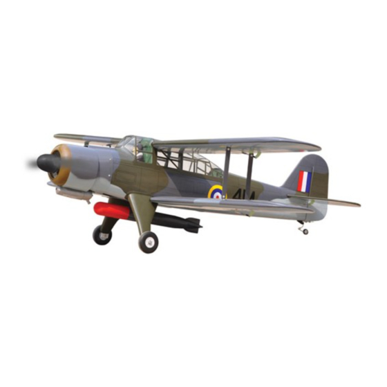
FAIREY ALBACORE
ALL BALSA - PLY WOOD CONSTRUCTION.
COVERED IN A HEAT-SHRINK FILM WITH PRINTED.
Glow and EP
95% ALMOST READY TO FLY
SPECIFICATION:
- Wingspan: 1,693mm (66.65in).
- Length: 1,400mm (55.12in).
- Weight: 4.5kg (9.9 lbs).
- Wing area: 75.74 dm .
- Wing loading: 59.41g/dm .
- Wing type: Naca Airfoil.
- Servo mount: 42mm x 21mm.
- Gear type: Aluminium Hi-grade for main gear
and spring wire for tail gear (included).
- Spinner: 70mm.
Instruction Manual Book
2
2
Item code: BH166.
Parts listing required (not included):
- Radio: 05 channels.
- Servo: 07 servos.
- Engine: 65 - 75 2 stroke ; 15 cc gas.
- Motor: Brushless outrunner 1200-2200W, 650KV.
- Propeller: Suit with your engine.
Recommended Motor
and Battery set up (not included):
- Motor: RIMFIRE.60.
- Lipo cell: 6 cells 4,000-5,000mAh.
- Receiver battery: 6V/ 1200-2000mAh NiMH.
- ESC: 80A.
Made in Vietnam.
Advertisement
Table of Contents

Related Manuals for Black Horce Model fairey albacore BH166


Summary of Contents for Black Horce Model fairey albacore BH166
- Page 1 Instruction Manual Book Item code: BH166. FAIREY ALBACORE ALL BALSA - PLY WOOD CONSTRUCTION. COVERED IN A HEAT-SHRINK FILM WITH PRINTED. Glow and EP 95% ALMOST READY TO FLY SPECIFICATION: - Wingspan: 1,693mm (66.65in). Parts listing required (not included): - Length: 1,400mm (55.12in). - Radio: 05 channels.
- Page 2 FAIREY ALBACORE Item code: BH166 This instruction manual is designed to help you build a great flying aeroplane. Please read this manual thoroughly before starting assembly of your FAIREY ALBACORE. Use the parts listing below to identify all parts. WARNING Please be aware that this aeroplane is not a toy and if assembled or used incorrectly it is capable of causing injury to people or property.
- Page 3 FAIREY ALBACORE Item code: BH166 TOOLS & SUPPLIES NEEDED EPOXY A EPOXY B Epoxy Glue (5 minute type). Hand or electric drill. Epoxy Glue (30 minute type). Threadlocker (screw cement). Hobby knife. Some more tools. Awl. Assorted drill bits. Phillips head screwdriver. - 2mm ball driver.
-
Page 4: Table Of Contents
FAIREY ALBACORE Item code: BH166 : Cockpit fuselage (8a1,8a2: Canopy) : Fuselage. : Pilot; c: Top hatch fuselage). : Wing panel ( 2a, 2b, 2c, 2d) : Horizontal stabilizer. Fuel Tank (9a: Clunk; 9b: Stopper (three line). : Rudder. : Aluminium wing dihedral brace. Tail gear set. - Page 5 FAIREY ALBACORE Item code: BH166 * Apply drops of thin CA to the top and bottom of each 1. INSTALLING THE AILERONS hinge. Do not use CA accelerator. After the CA has fully hardened, test the hinges by pulling on the aileron. C/A glue.
-
Page 6: 100Mm Push Rod
FAIREY ALBACORE Item code: BH166 2x10mm High Wing Bottom view 2x10mm Low Wing Bottom view 2x10mm 2 x 10mm Screw - - - - 16 3. INSTALLING THE CONTROL HORNS, LINKAGES Silicone tube - - - 4 Silicone Tube 2mm Nut - - - - - - 100mm Push rod Silicone Tube... -
Page 7: 4X20Mm Cap Screw
FAIREY ALBACORE Item code: BH166 Repeat the procedure to install the opposite gear. High Wing Bottom view Low Wing 4. INSTALLING THE ENGINE MOUNT OPTION 1: ELECTRIC MOTOR 4x70mm Cap Screw 5x5mm Aluminum - - 4 - - - - - 4 4x20mm Cap Screw 10x50mm Aluminum - - -... - Page 8 FAIREY ALBACORE Item code: BH166 4x20mm Secure 4x70mm Secure...
-
Page 9: 4Mm Nut
FAIREY ALBACORE Item code: BH166 OPTION 2: ENGINE INSTALLATION 4mm Nut - - - - - - - 8 Installing the engine mount, fuel tank 4x30mm Cap Screw - - - - - - - 8 4mm Washer - - - - - - - 4 4mm Spring Washer Engine mount - - - - - - - 8... - Page 10 FAIREY ALBACORE Item code: BH166 Feed three lines through the fuel tank Fuel tank compartment and through the pre-drilled hole in the firewall. Pull the lines out from behind the engine, while guiding the fuel tank into place. Push the fuel tank as far forward as possible, the front of the tank should just about touch the back of the firewall.
- Page 11 FAIREY ALBACORE Item code: BH166 5. INSTALLING THE FUSELAGE SERVOS Fuselage bottom side 1) Install the rubber grommets and brass collets into the elevator, rudder and throttle servos. Test fit the servos into the servo tray. Trim the tray if necessary to fit your servos.
- Page 12 FAIREY ALBACORE Item code: BH166 6. COWLING Slide the cowl back over the engine and secure it in 1) Slide the fiberglass cowl over the engine and line up place using four wood screws. See picture below. the back edge of the cowl with the marks you made on the fuselage.
- Page 13 FAIREY ALBACORE Item code: BH166 3) Check the fit of the horizontal stabilizer in its slot. 7. INSTALLING HORIZONTAL STABILIZER Make sure the horizontal stabilizer is square and centered to the fuselage by taking measurements, but Silicone tube don't glue anything yet. - - - 2 2mm Nut - - - - - -...
- Page 14 FAIREY ALBACORE Item code: BH166 ELEVATOR CONTROL HORN AND PUSHROD INSTALLATION Elevator pushrod Control horn and linkages for Elevator are installed the same way as the ailerons before (see page 5). Silicone Tube Bottom side. Horn Drill a hole 1.5 mm A+B Epoxy glue 1) Using pliers, carefully make a 90 degree bend down at the mark made.
- Page 15 FAIREY ALBACORE Item code: BH166 Top side. Control horn and linkages for Rudder are installed the same way as the Elevator before (see page 10). Rudder Rudder pushrod Silicone Tube Silicone Tube A+B Epoxy glue Pushrod Control horn Mark Rudder Flaslink Flaslink servo arm...
- Page 16 FAIREY ALBACORE Item code: BH166 Secure the gear to the fuselage. Fuselage Bottom side Secure 4x15mm C/A glue Epoxy glue Install and secure the wheel. Collar C/A glue...
- Page 17 FAIREY ALBACORE Item code: BH166 Mark the locations of the two mounting screws. 10. MOUNTING THE TAIL WHEEL BRACKET Remove the tail wheel bracket and drill 2.5mm pilot holes at the locations marked. Set the tail wheel assembly in 3x12mm Screw - - - 2 place on the plywood plate.
- Page 18 FAIREY ALBACORE Item code: BH166 11. INSTALLING PLASTIC BOMB FUSELAGE - - - 2 - - - 2 - - - 2 Fuselage Bottom side Remove the film covering. A+B Epoxy glue. 12. INSTALLING THE SWITCH, RECEIVER AND BATTERY 1) Cut out the switch hole using a modeling knife. Use a 4) Wrap the receiver and battery pack in the protective 2mm drill bit and drill out the two mounting holes foam to protect them from vibration.
- Page 19 FAIREY ALBACORE Item code: BH166 Fuselage top side Switch Zip tie Zip tie Fuel tank Receiver Zip tie Battery 13. INSTALLING COCKPIT FUSELAGE Cut and remove A+B Epoxy glue. Position the canopy so the rear frame on the canopy is aligned with the rear edge of the cockpit opening. Use canopy glue to secure the canopy to the canopy hatch.
- Page 20 FAIREY ALBACORE Item code: BH166 14. WING ATTACHMENT, WING STRUT - - - 8 - - - 8 - - - 8 12mm Aluminium tube. 178mm 522mm 185mm Remove the film covering. A+B Epoxy glue. High Wing Bottom view Low Wing Top view...
- Page 21 FAIREY ALBACORE Item code: BH166 *** Test fit the aluminium tube dihedral brace into each wing haft. The brace should slide in easily. If not, use 220 grit sand around the edges and ends of the brace until it fits properly. Attach the aluminium tube into the fuselage.
- Page 22 FAIREY ALBACORE Item code: BH166 15. INSTALLING THE SPINNER, PROPELLER - - - - - - 2...
- Page 23 FAIREY ALBACORE Item code: BH166 BALANCING CONTROL THROWS 1) It is critical that your airplane be balanced correctly. 1) We highly recommend setting up a plane using the Improper balance will cause your plane to lose control control throws listed. and crash.
- Page 24 I/C FLINGT WARNINGS Always operate in open areas, away from NEVER fly near power lines,aerials or ALWAYS adjust the engine from behind factories, hospitals, schools, buildings the propeller, and do not allow any part of other dangerous areas including airports, and houses etc.
Need help?
Do you have a question about the fairey albacore BH166 and is the answer not in the manual?
Questions and answers