Table of Contents
Advertisement
Quick Links
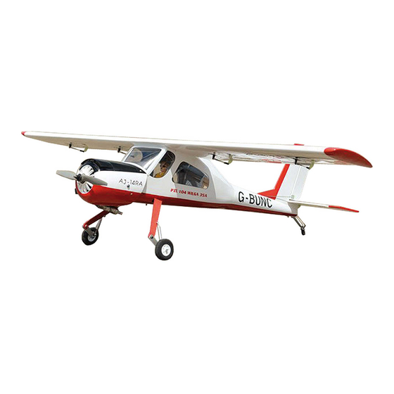
PZL 104 Wilga
ALL BALSA - PLY WOOD CONSTRUCTION.
COVERED WITH ORACOVER
95% ALMOST READY TO FLY
SPECIFICATION
- Wingspan: 1,720mm (67.72 in).
- Length: 1,320 mm (51.97 in).
- Weight: 3.9 kg (8.58 lbs).
- Wing area: 41dm
- Wing loading: 95.12g/dm
- Wing type: Naca Airfoil.
- Gear type: Aluminium Hi-grade
and oleo struts for main gear (included).
- Servo mount: 42mm x 21mm.
Instruction Manual Book
.
2
.
2
Item code: BH156.
Parts listing required (not included):
- Radio: 05 channels.
- Servo: 07 servos.
- Engine: 61 - 2 stroke; 15cc Gas.
- Motor: Brushless outrunner 1200-2200W, 650KV.
- Propeller: Suit with your engine.
Recommended motor
and battery set up (not included):
- Motor: RIMFIRE.60.
- Lipo cell: 6 cells 4,000-5,000mAh.
- Receiver battery: 6V/ 1200-2000mAh NiMH.
- ESC: 80A.
Made in Vietnam.
Advertisement
Table of Contents

Related Manuals for Black Horce Model PZL 104 Wilga


Summary of Contents for Black Horce Model PZL 104 Wilga
- Page 1 Instruction Manual Book Item code: BH156. PZL 104 Wilga ALL BALSA - PLY WOOD CONSTRUCTION. COVERED WITH ORACOVER 95% ALMOST READY TO FLY SPECIFICATION - Wingspan: 1,720mm (67.72 in). Parts listing required (not included): - Length: 1,320 mm (51.97 in).
-
Page 2: Tools And Supplies Needed
PZL 104 Wilga. Item code: BH156. Instruction Manual This instruction manual is designed to help you build a great flying aeroplane. Please read this manual thoroughly PZL 104 Wilga before starting assembly of your . Use the parts listing below to identify all parts. -
Page 3: Safety Precaution
PZL 104 Wilga. Item code: BH156. Instruction Manual Caution: This model is not a toy! This model is highly pre-fabricated and can be built in If you are a beginner to this type of powered model, a very short time. However, the work which you have to please ask an experienced model flyer for help and carry out is important and must be done carefully. -
Page 4: Installing The Aileron Servos
PZL 104 Wilga. Item code: BH156. Instruction Manual REPLACEMENT SMALL PARTS 4x15mm 3x15mm 5x35mm 2x10mm 4x15mm 3x12mm 1. Aluminium landing gear. 2. Wheels. 3. Tail gear set. 4x20mm 4. Spinner 4x30mm 4x70mm 5. Fuel tank. 5a. Clunk. 5b. Stopper (three line). -
Page 5: Installing The Aileron Linkages
PZL 104 Wilga. Item code: BH156. Instruction Manual 3) Place the servo into the servo tray. Center the servo within the tray and drill 1.5mm pilot holes through the block of wood for each of the four mount- ing screws provided with the servo. -
Page 6: Installing The Engine Mount
PZL 104 Wilga. Item code: BH156. Instruction Manual III. INSTALLING THE ENGINE MOUNT Silicone Tube See pictures below: Bend and cut. Insert the 90 degree bend down through the hole in the control horn. Install one nylon snap keeper over the wire to secure it to the control horn. -
Page 7: Option 2: Engine Mount
PZL 104 Wilga. Item code: BH156. Instruction Manual 1. INSTALLING THE STOPPER ASSEMBLY 1) The stopper has been pre-assembled at the factory. 2) Using a modeling knife, cut one length of silicon fuel line (the length of silicon fuel line is calculated by... -
Page 8: Installing The Throttle Pushrod
PZL 104 Wilga. Item code: BH156. Instruction Manual 8) Feed three lines through the fuel tank compart- ment and through the pre-drilled hole in the firewall. Pull the lines out from behind the engine, while guiding the Throttle servo fuel tank into place. -
Page 9: Installing Horizontal Stabilizer
PZL 104 Wilga. Item code: BH156. Instruction Manual 4) Check the fit of the horizontal stabilizer in its V. INSTALLING HORIZONTAL slot. Make sure the horizontal stabilizer is square and STABILIZER centered to the fuselage by taking measurements, but don’t glue anything yet. -
Page 10: Elevator Control Horn Installation
PZL 104 Wilga. Item code: BH156. Instruction Manual When you are sure that everything is aligned correctly, mix up a generous amount of 30 minute epoxy. Apply a thin layer to the top and bottom of the stabilizer mounting area and to the stabilizer mounting platform sides in the fuselage. -
Page 11: Mounting The Tail Wheel Bracket
PZL 104 Wilga. Item code: BH156. Instruction Manual Silicone Tube Pushrod Control horn Push in Mark Rudder Rudder pushrod Secure Rudder servo Connector Servo arm VII. GEAR INSTALATION 4x15mm RUDDER CONTROL HORN INSTALLATION 3x15mm Rudder control horn install as same as method of elevator control horn. -
Page 12: Installing The Switch, Receiver And Battery
PZL 104 Wilga. Item code: BH156. Instruction Manual Install and secure the wheel. Secure Secure and apply threadlocker (screw cement). 5x35mm 3x15mm Rudder servo XIII. INSTALLING THE SWITCH, RECEIVER AND BATTERY 1) Cut out the switch hole using a modeling knife. - Page 13 PZL 104 Wilga. Item code: BH156. Instruction Manual Position the canopy so the rear frame on the canopy is aligned with the fuselage. Use canopy glue to secure the canopy to the fuselage. Use low-tack tape to hold the canopy in position until the glue fully cures. Wrap the tape completely around the fuselage.
-
Page 14: Wing Attachment
PZL 104 Wilga. Item code: BH156. Instruction Manual Insert the wing panel as pictures below. 3) Slide the cowl back over the engine and secure it in place using four wood screws. See picture below. 4) Install the muffler and muffler extension onto the engine and make the cutout in the cowl for muffler clearance. -
Page 15: Control Throws
PZL 104 Wilga. Item code: BH156. Instruction Manual BALANCING CONTROL THROWS 1) It is critical that your airplane be balanced cor- 1) We highly recommend setting up a plane using rectly. Improper balance will cause your plane to lose the control throws listed. - Page 16 I/C FLINGT WARNINGS Always operate in open areas, away ALWAYS adjust the engine from from factories, hospitals, schools, NEVER fly near power lines, behind the propeller, and do not buildings and houses etc. NEVER aerials or other dangerous areas allow any part of your body to be in fly your aircraft close to people or including airports, motorways etc.
Need help?
Do you have a question about the PZL 104 Wilga and is the answer not in the manual?
Questions and answers