Table of Contents
Advertisement
Quick Links
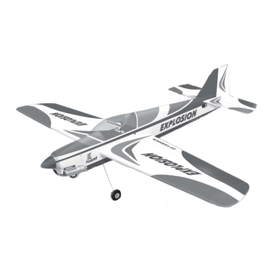
Instruction Manual book
SPECIFICATION
Wingspan :
Length
Weight
Radio
Servo
Glow Engine:
Motor
1,400 mm
:
1,360 mm
:
1.5 kg
:
04 channels.
:
04 - 05 servos.
25 -32
:
AXI 2826/10
55.12 in.
53.54 in.
3.3 Lbs.
2 Stroke.
Made in Vietnam.
ITEM CODE: BH40.
Advertisement
Table of Contents

Related Manuals for Black Horce Model Explosion BH40


Summary of Contents for Black Horce Model Explosion BH40
- Page 1 Instruction Manual book ITEM CODE: BH40. SPECIFICATION Wingspan : 1,400 mm 55.12 in. Length 1,360 mm 53.54 in. Weight 1.5 kg 3.3 Lbs. Radio 04 channels.
-
Page 2: Instruction Manual
EXPLOSION Instruction Manual. This instruction manual is designed to help you build a great flying aeroplane. Please read this manual thoroughly before starting assembly of your EXPLOSION . Use the parts listing below to identify all parts. WARNING. Please be aware that this aeroplane is not a toy and if assembled or used incorrectly it is capable of causing injury to people or property. -
Page 3: Safety Precaution
EXPLOSION INSTRUCTION MANUAL. SAFETY PRECAUTION. + This is not a toy + Be sure that no other flyers are using your radio frequency. Cut the covering + Do not smoke near fuel away from the slot. + Store fuel in a cool, dry place, away from children and pets. - Page 4 EXPLOSION Instruction Manual. 5) Drill 1,6mm pilot holes through the block of wood for each of the four mounting screws provided with the servo. Electric wire. Straigh line. C/A glue 2) Insert aileron control horn to the aileron. C/A glue Repeat the procedure for the other wing half.
- Page 5 EXPLOSION INSTRUCTION MANUAL. Cut. C/A glue. 3x25mm. Repeat the procedure for the other wing half. THERE ARE TWO OPTIONS: 1. ELECTRIC MOTOR 2. ENGINE MOUNT. OPTION 1: ELECTRIC MOTOR INSTALLING ELECTRIC MOTOR. Push.
-
Page 6: Installing The Receiver And Battery
EXPLOSION Instruction Manual. Motor. Rotor shaft. Front view. INSTALLING THE RECEIVER AND BATTERY. 1) Plug the servo leads and the switch lead into the receiver. You may want to plug an aileron extension into the receiver to make plugging in the aileron servo lead easier when you are installing the wing . -
Page 7: Option 2: Engine Mount
EXPLOSION INSTRUCTION MANUAL. 2) While keeping the back edge of the OPTION 2: ENGINE MOUNT. cowl flush with the marks, align the front of INSTALLING THE ENGINE MOUNT. the cowl with the crankshaft of the motor. The front of the cowl should be positioned so the crankshaft is in nearly the middle of the cowl opening. - Page 8 EXPLOSION Instruction Manual. 8. Feed three lines through the fuel tank compartment and through the pre-drilled hole in the firewall. Pull the lines out from behind the engine, while guiding the fuel tank into place. Push the fuel tank as far forward as possible, the front of the tank should just about touch the back of the firewall.
-
Page 9: Installing The Engine
EXPLOSION INSTRUCTION MANUAL. INSTALLING THE ENGINE. Pushrod wire. Locate the long piece of wire used for the throttle pushrod. One end of the wire has been pre-bend in to a “Z” bend at the factory. This “Z” bend should be inserted into the throttle arm of the engine when the engine is fitted onto the engine mount. -
Page 10: Installing The Spinner
EXPLOSION Instruction Manual. 2) While keeping the back edge of the INSTALLING THE SPINNER. cowl flush with the marks, align the front of the cowl with the crankshaft of the motor. The front of the cowl should be positioned so the crankshaft is in nearly the middle of the cowl opening. -
Page 11: Horizontal Stabilizer Installation
EXPLOSION INSTRUCTION MANUAL. HORIZONTAL STABILIZER INSTALLATION. 1) Using a modeling knife, remove the Cut the covering covering at servo tray (only left side of fuselage) away from the slot. and at fuselage slot. Temporary pin to keep hinge centered. Remove covering. -
Page 12: Elevator Control Horn Installa- Tion
EXPLOSION Instruction Manual. Epoxy glue. Mark point 5. After the epoxy has fully cured, removethe masking tape or T-pins used to hold thestabilizer in place and carefully 3. Remove the stabilizer. Using the lines inspect theglue joints. Use more epoxy you just drew as a guide, carefully remove the to fill in any gaps that were not filled covering from between them using a modeling... -
Page 13: Elevator Pushrod Installation
EXPLOSION INSTRUCTION MANUAL. Hinge. Elevator control horn. ELEVATOR PUSHROD INSTALLATION. Pushrod install as same as method of pushrod wing. See pictures below: Cut the covering away from the slot. Temporary pin to keep hinge centered. Assemble then apply drops of thin C/A to center of hinge,on both sides. - Page 14 EXPLOSION Instruction Manual. 1) Using a modeling knife, remove the covering from the top of the fuselage and the covering from over the precut hinge slot cut into the lower rear portion of the fuselage This slot accepts the lower vertical. Remove covering.
-
Page 15: Main Gear Installation
EXPLOSION INSTRUCTION MANUAL. Elevator servo. Rudder servo. C/A glue. RUDDER CONTROL HORN INSTALLA- MAIN GEAR INSTALLATION. TION. Rudder control horn install as same as 3 x 12mm. method of aileron control horn. Please see picture below. Rudder control horn ... -
Page 16: Installing The Throttle Servo
EXPLOSION Instruction Manual. INSTALLING THE RECEIVER AND BATTERY. 1. Plug the servo leads and the switch lead into the receiver. You may want to plug an aileron extension into the receiver to make plugging in the aileron servo lead easier when you are installing the wing . - Page 17 EXPLOSION INSTRUCTION MANUAL. Battery. Secure the wing ceiver. ATTACHMENT WING-FUSELAGE. See pictures below: Installing the canopy hatch as same as Remove covering. picture below. Dihedral brace.
-
Page 18: Control Throws
EXPLOSION Instruction Manual. BALANCING. CONTROL THROWS. 1) It is critical that your airplane be balanced 1) We highly recommend setting up a correctly. Improper balance will cause your plane using the control throws listed.
Need help?
Do you have a question about the Explosion BH40 and is the answer not in the manual?
Questions and answers