Table of Contents
Advertisement
Instruction Manual
D200137X012
r
Fisher
3570 Pneumatic Valve Positioners
Contents
. . . . . . . . . . . . . . . . . . . . . . . . . . . . . . . . .
. . . . . . . . . . . . . . . . . . . . . . . . . . . . .
. . . . . . . . . . . . . . . . . . . . . . . . . . . . . . . . .
. . . . . . . . . . . . . . . . . . . . . . . . . . . . . . .
. . . . . . . . . . . . . . . . . . . . . . . . .
. . . . . . . . . . . . . . . . . . . . . . . . . . . . . . . . .
. . . . . . . . . . . . . . . . . . . . . . . . . . . . . . . .
. . . . . . . . . . . . . . . . . . . . . . . . . . . . .
. . . . . . . . . . . . . . . . . . . . . . . . . . . . . . . . . . .
. . . . . . . . . . . . . . . . . . . . . . . .
. . . . . . . . . . . . . . . . . . . . . . . . . .
. . . . . . . . . . . . . . . . . . . . . . . .
. . . . . . . . . . . . . . . . . . . . . . . . . . . .
. . . . . . . . . . . . . . . . . . . . . . . . . . . . . . . .
. . . . . . . . . . . . . . . . . . . . . . . . . . . .
. . . . . . . . . . . . . . . . . . . . . . . . . . . . . .
. . . . . . . . . . . . . . . . . . . . . . . . . . . .
. . . . . . . . . . . . . . . . . . . . . . . . . . . . . .
Introduction
Scope of Manual
This manual provides installation, operation, adjustment, maintenance, and parts ordering information for Fisher
3570 pneumatic valve positioners. The various product types within this series are described later in this manual. Refer
www.Fisher.com
. . . . . . . . . . . . .
. . . . . . . . . .
. . . . .
. . . . . . . . . . . . . .
. . . . . . . . . . . . . . . . . . . .
. . . . . . . . . . . . . . . . . .
. . . . . . . . . . . . . . . . . . . . . .
. . . . . . . . . . . . . . . . . .
. . . . . . . . . . . . . . . . . . . . . . .
. . . . . . . . . .
. . . . . . . . . . . . . . . . . . . .
. . . . . . . . . . . . . .
. . . . . . . . . . . . . .
. . . . . . . . . . . . . . . . . . . .
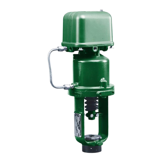
Figure 1. Fisher 3570 Positioner Mounted on
470 Actuator
1
1
2
2
4
4
5
5
6
7
7
8
9
10
10
11
11
11
12
15
15
17
17
W5566
18
19
20
21
22
23
. . . . . . . . . . . . . . . . . . . . . . . . . . . . . . . . . . .
24
24
24
. . . . . . . . . . . . . . . . . . . . . . . . . . . . . . . . . . .
3570 Positioners
. . . . . . . . . . . . . . . . . . . . . . . . . . . . . . . .
. . . . . . . . . . . . . . . . . . . . . . . . . . . .
. . . . . . . . . . . . . . . . . . . . . . . . . . . . . .
. . . . . . . . . . . . . . . . . . . . . . . . . . . . . . .
. . . . . . . . . . . . . . . . . . . . . . . .
. . . . . . . . . . . . . . .
. . . . . . . . . . . . . . . . . . . .
September 2015
25
25
25
25
26
26
26
26
26
Advertisement
Table of Contents

Related Manuals for Fisher 3570

![Controller Fisher] 3660 Instruction Manual](https://static-data2.manualslib.com/product-images/3ac/1225055/60x60/fisher-3660-controller.jpg)
![Controller Fisher] 3661 Instruction Manual](https://static-data2.manualslib.com/product-images/e75/1225055/60x60/fisher-3661-controller.jpg)


Summary of Contents for Fisher 3570
-
Page 1: Table Of Contents
....Introduction Scope of Manual This manual provides installation, operation, adjustment, maintenance, and parts ordering information for Fisher 3570 pneumatic valve positioners. The various product types within this series are described later in this manual. Refer www.Fisher.com... -
Page 2: Description
Do not install, operate or maintain a 3570 positioner without being fully trained and qualified in valve, actuator, and accessory installation, operation, and maintenance. To avoid personal injury or property damage, it is important to carefully read, understand and follow all the contents of this manual, including all safety cautions and warnings. - Page 3 Instruction Manual 3570 Positioners D200137X012 September 2015 Table 1. Specifications Available Configurations Supply Medium Air or Natural Gas See the positioner type number descriptions given above. Supply medium must be clean, dry, and noncorrosive Per ISA Standard 7.0.01 Input Signal A maximum 40 micrometer particle size in the air Standard Ranges: 0.2 to 1.0 bar (3 to 15 psig) or 0.4...
-
Page 4: Specifications
NOTE: Specialized instrument terms are defined in ANSI/ISA Standard 51.1 - Process Instrument Terminology. 1. For a 3570 or 3570C positioner mounted on a 470 or 480 actuator. Values do not apply to other constructions or actuator‐valve combinations. 2. m /h at 0°C, 1.01325 bar, absolute (Scfh at 60°F, 14.7 psia). -
Page 5: Installation, Mounting, And Connections
D For 3570, 3570C, 3572, and 3573 positioners, mount the positioner with two cap screws (key 32, figure 10). If the range and bias springs are not installed in the positioner, refer to the range spring and bias spring procedures in the Maintenance section. -
Page 6: Diagnostic Test Connections (Optional)
To support diagnostic testing of the control valve assembly, the connectors, piping, and other hardware can be installed between the 3570 positioner and the actuator. A typical connector installation is shown in figure 3. For connectors, refer to the FlowScanner Diagnostic Connection kit listing in the parts list. -
Page 7: Connections
Connections Piping Sizes All pressure connections on 3570 positioners are 1/4 NPT (internal). Use 3/8‐inch pipe or tubing for supply, cylinder (bottom connection), and instrument (input signal) connections. For the remote vent pipe, if one is required, use 19 mm (3/4‐inch) (minimum inside diameter) pipe for runs up to 6.09 meters (20 feet). For vent piping runs from 6.09 to 30.5 meters (20 to 100 feet), use 25.4 mm (1‐inch) (minimum inside diameter) pipe. -
Page 8: Vent
Instruction Manual 3570 Positioners September 2015 D200137X012 Figure 4. Typical Location of Fisher 3570 Positioner Parts and Adjustments BELLOWS RANGE SPRING CLEAN‐OUT (SPAN ADJUSTMENT) PLUNGER VERTICAL CYLINDER RELAY BOTTOM HORIZONTAL PRESSURE RELAY INSTRUMENT SUPPLY PRESSURE CONNECTION (NOT SHOWN) (1/4 NPT) -
Page 9: Supply Pressure Connections
Instruction Manual 3570 Positioners D200137X012 September 2015 The connection marked VENT (see figure 4) should be left open if the actuator is installed in the vertical position. However, the vent must be protected against the entrance of any foreign material that could plug it. Check the vent periodically to be certain it is not plugged. -
Page 10: Cylinder Connections
2. The cylinder top connection is a pressure passage located in the bottom of the positioner base (key 1, figure 10). On 3570 and 3570C positioners, an O‐ring (key 33, figure 10) is used between the bottom of the positioner and the top of the actuator. -
Page 11: Operating Information
Emerson Process Management sales office for assistance in determining if a new range spring, bias spring, and spring retainer/spacer are required. Refer to the Range Spring, Bias Spring, and Spring Retainer/Spacer Selection for 3570 Pneumatic Valve Positioners Instruction Manual Supplement (D104021X012). Adjustment Procedures Refer to figure 2. -
Page 12: Changing Positioner Action
For all 3570 positioners, examine the end of the beam near the bias spring (see figure 2). The beam should be approximately centered between the two E‐ring travel stops. Observing the caution above for 3570C and 3570PC positioners, rotate the nozzle(s) to center the beam between the E‐rings. - Page 13 Instruction Manual 3570 Positioners D200137X012 September 2015 Figure 5. Bellows Mounting for Direct and Reverse Action RESTRICTOR BELLOWS TOP VIEW WITH OPTIONAL RE STRICTOR BELLOWS BASE BEAM BEAM BELLOWS BASE PEDESTAL PEDESTAL DIRECT REVERSE ACTION ACTION 1—MOUNTING SCREW 2—MOUNTING SCREW 3—BELLOWS POST...
- Page 14 Instruction Manual 3570 Positioners September 2015 D200137X012 3. Two bellows posts are provided. The posts are screwed into storage holes in the positioner base immediately above the CYLINDER and INSTRUMENT connections. Unscrew these posts. Note An optional restrictor (see the top view in figure 5) can be found in place of one of the bellows mounting screws (number 1). If so, note the location of the restrictor and replace it in the same location during reassembly.
-
Page 15: Split Range Operation
Split Range Operation 3570 valve positioners are suitable for split range operation. In split range operation, two or more control valves are operated by one output signal from a single control device. When two control valves are split ranged, one valve strokes fully with one half the input signal range and the second valve strokes fully with the other half of the input signal range. - Page 16 Instruction Manual 3570 Positioners September 2015 D200137X012 6. Rotate the cable spool to obtain the correct initial range spring extension. Each full revolution of the spool extends the range spring 50.8 mm (2 inches) [6.4 mm (1/4‐inch) for 1/8 revolution]. If the initial range spring extension is not specified, calculate it using one of the equations given below.
-
Page 17: Principle Of Operation
In the 3570 and 3570C positioners, the piston movement is fed back to the beam by means of a range spring, which is connected to the beam and to the piston rod extension. In the 3570P, 3570PC, and 3571 positioners, the feedback is provided to the range spring by a cable or wire that is connected to the actuator‐valve stem connector. -
Page 18: 3572 And 3576 Valve Positioners
For the 3576 positioner, the principle of operation is identical to the 3572 positioner but the actuator can be a direct or reverse acting pneumatic diaphragm actuator. Figure 7. Schematic Diagram of Fisher 3572 Positioner with a 472 Pneumatic Piston Actuator BELLOWS... -
Page 19: 3573 And 3577 Valve Positioners
Refer to the schematic diagram in figure 8, which shows the 3573 positioner mounted on a 473 pneumatic piston actuator. For the 3577 positioner, the principle of operation is identical to the 3573 positioner, but the actuator can be direct or reverse acting. Figure 8. Schematic Diagram of Fisher 3573 Positioner with 473 Pneumatic Piston Actuator BELLOWS REVERSED... -
Page 20: Relay Operation
Instruction Manual 3570 Positioners September 2015 D200137X012 relay action, the pressure to the underside of the piston decreases. The force exerted by the actuator spring overcomes the force of the pressure below the piston, and the piston moves downward. This changes the valve plug position. -
Page 21: Maintenance
Instruction Manual 3570 Positioners D200137X012 September 2015 Figure 9. Sectional View of a Typical Relay NOZZLE AND LOCKNUT USED WITH 3570C AND 3570PC POSITIONERS 40A8972‐B/DOC EXHAUST OUTPUT CLEAN‐OUT PLUNGER SUPPLY A-SUPPLY PRESSURE AREA B-RELAY OUTPUT PRESSURE VALVE NOTES: C-EXHAUST VALVE... -
Page 22: Troubleshooting
Instruction Manual 3570 Positioners September 2015 D200137X012 D Do not remove the actuator from the valve while the valve is still pressurized. D Disconnect any operating lines providing air pressure, electric power, or a control signal to the actuator. Be sure the actuator cannot suddenly open or close the valve. -
Page 23: Converting A 3570 Valve Positioner To A 3570C Valve Positioner
Converting a 3570 Valve Positioner to a 3570C Valve Positioner If desired, tire valves can be substituted for pressure gauges. Also, locking relay nozzles can be added on any 3570 positioner. This provides the construction that is standard with 3570C and 3570PC positioners. -
Page 24: Range Spring
4. Disconnect the other end of the range spring by performing one of the following steps: D For 3570, 3570C, 3572, and 3573 positioners, use a screwdriver to remove the spring retainer (key 19, figure 2) from the piston rod extension. -
Page 25: Bias Spring
Use only genuine Fisher replacement parts. Components that are not supplied by Emerson Process Management should not, under any circumstances, be used in any Fisher instrument. Use of components not supplied by Emerson may void your warranty, might adversely affect the performance of the valve, and could cause personal injury and property damage. -
Page 26: Parts Kits
Parts List Positioner Common Parts (figures 10 and 11) Note Parts kits for 3570 positioners contain the gaskets, diaphragms, and O‐ring seals as specified by the type and temperature limitations. Parts Note are for 3570, 3570C, 3570P, and 3570PC positioners. - Page 27 For 3570C only Fluorocarbon (hi‐temp. const.) Hex nut, brass Machine screw, pl steel For 3570, 3571, 3573 (2 req'd) For 3570, 3570C, 3571 (6 req'd) For 3572, 3576, 3577 (1 req'd) For 3572, 3573, 3576, 3577 (3 req'd) For 3570C (none req'd)
- Page 28 For direct‐acting units Pipe plug, pl steel For reverse‐acting units Cover gasket, Cylinder tubing assembly, copper Cork (std. const.) For 3570, 3571, 3573, 3577 Silicone (hi‐temp. const.) Cover screw, pl steel (4 req'd) Bolt, brass Cover, aluminum w/o restrictor assembly (2 req'd) Washer, brass plated (2 req'd) w/restrictor assembly (1 req'd)
- Page 29 Positioner extension assembly, aluminum Spring retainer spacer, SST Washer, SST For 3572, 3576 (1 req'd) For 3570, 3571, 3573, 3577 (2 req'd) Note Spring retainer spacer, SST Refer to figure 13 for keys 86 through 101. 104.8 mm (4‐1/8 inches) maximum actuator travel, 54.0 mm (2‐1/8 inches) or less valve travel...
- Page 30 Instruction Manual 3570 Positioners September 2015 D200137X012 Figure 13. Fisher 3570P and 3570PC Positioner VIEW A‐A TYPICAL MOUNTING FOR 3570P AND 3570PC POSITIONERS 41A7131‐A B1839...
- Page 31 Instruction Manual 3570 Positioners D200137X012 September 2015...
- Page 32 Responsibility for proper selection, use, and maintenance of any product remains solely with the purchaser and end user. Fisher and FlowScanner are marks owned by one of the companies in the Emerson Process Management business unit of Emerson Electric Co. Emerson Process Management, Emerson, and the Emerson logo are trademarks and service marks of Emerson Electric Co.
Need help?
Do you have a question about the 3570 and is the answer not in the manual?
Questions and answers