Table of Contents
Advertisement
Instruction Manual
Form 1837
November 1992
3570 Series Pneumatic Valve Positioners
Contents
. . . . . . . . . . . . . . . . . . . . . . . . . . . . . . .
. . . . . . . . . . . . . . . . . . . . . . . . . . . . .
. . . . . . . . . . . . . . . . . . . . . . . . . . . . . . . . . .
. . . . . . . . . . . . . . . . . . . . . . . . . . . . . . .
. . . . . . . . . . . . . . . . . . . . . . . . . . . . . .
. . . . . . . . . . . . . . . . . . . . . . . . . . . . . . . . . .
Diagnostic Test Connections (Optional)
. . . . . . . . . . . . . . . . . . . . . . . . . . . . . . . .
. . . . . . . . . . . . . . . . . . . . . . . . . . . . . . . . . . . . . .
. . . . . . . . . . . . . . . . . . . . . . . . . . .
for Type 3570P and 3570PC Positioners
. . . . . . . . . . . . . . . . . . . . . . . . . . .
. . . . . . . . . . . . . . . . . . . . . . . . . . . . .
. . . . . . . . . . . . . . . . . . . . . . . . . . .
. . . . . . . . . . . . . . . . . . . . . . . . . . . . . .
. . . . . . . . . . . . . . . . . . . . . . . . . . . . .
. . . . . . . . . . . . . . . . . . . . . . . . . . . . . . . .
. . . . . . . . . . . . . . . . . . . . . . . . . . . . . . .
. . . . . . . . . . . . . . . . . . . . . . . . . . . . .
Assembly
. . . . . . . . . . . . . . . . . . . . . . . . . . . . . . . .
. . . . . . . . . . . . . .
. . . . . . . .
. . . . . . . . . . . . . . . .
. . . . . . . . . . . . . . . . . . . . . . . .
. . . . . . . . . . . . . . . . . . . . . .
. . . . . . . . . . . . . . . . . . .
. . . . . . . . . . . . . . . . . . . . . . . . .
. . . . . . . . . . . . . . . . . . . . . . . . .
. . . . . . . . . . . . . . . . . . . . . . .
. . . . . . . . . . . . . . . . . .
. . . . . . . . . . . . . . . . . . . . . .
. . . .
. . . . . . . . . . . . . . . . . .
. . . . . . . . . . . . . . . . . . .
. . . . . . . .
. . . . . . . .
. . . . . . . . . . . . . .
2
2
2
2
4
4
4
4
4
4
6
7
7
7
7
W5566*/IL
8
8
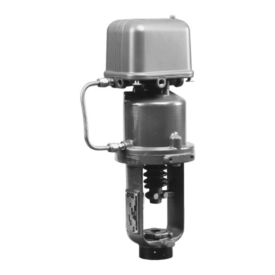
Figure 1. T ype 3570 Positioner Mounted
8
12
13
13
14
14
15
16
16
Parts Ordering
17
18
Parts Kits
. . . . . . . . . . . . . . . . . . . . . . . . . . . . . . . .
Positioner Repair Kits
18
Diagnostic Test Connection Kits
19
19
20
. . . . . . . . . . . . . . . . . . . . . . . . . . . . . . . . .
20
20
20
3570 Series
on T ype 470 Actuator
. . . . . . . . . . . . . . . . . . . . . . . . . . .
. . . . . . . . . . . . . . . . . . . . . . .
. . . . . . . . . . . . .
. . . . . . . . . . . . . . . . . . .
. . . . . . . . . . . . . . . . . . . . . .
20
20
20
20
21
21
23
Advertisement
Table of Contents

Subscribe to Our Youtube Channel
Related Manuals for Fisher 3570C


Summary of Contents for Fisher 3570C
-
Page 1: Table Of Contents
Principle of Operation ....Type 3570, 3570C, 3570P, 3570PC, and 3571 Valve Positioners .... -
Page 2: Introduction
Type 3570 — Pneumatic valve positioner with two actuator cylinder. Actuator stem position feedback is pro- relays for use with Fisher 470 and 480 Series pneu- vided through an extension of the actuator piston rod. matic piston actuators. See figure 2. The positioner includes three pressure gauges for input signal, for Type 3573 —... -
Page 3: Specifications
1. These terms are defined in ISA Standard S51.1:1979. 2. For a Type 3570 or 3570C positioner mounted on a Type 470 or 480 actuator. Values do not apply to other constructions or actuator-valve combinations. 3. Scfh at 60 F, 14.7 psia (m /h at 0 C, 1.01325 bar, absolute). -
Page 4: Installation, Mounting, And Connections
FlowScanner is a mark owned by Fisher Controls International, Inc. - Page 5 3570 Series RANGE SPRING CLEAN-OUT (SPAN ADJUSTMENT) PLUNGER BELLOWS CYLINDER BOTTOM HORIZONTAL VERTICAL PRESSURE RELAY RELAY INSTRUMENT PRESSURE SUPPLY CONECTION (NOT SHOWN) (1/4-INCH NPT) CYLINDER RELAY NOZZLE (TOP (OUTPUT PRESSURE CONNECTION) ADJUSTMENT (O-RING, VENT CONNECTION KEY 33) INSTRUMENT 3/8-INCH NPT CYLINDER BELLOWS CONECTION...
-
Page 6: Supply Pressure Connections
3570 Series influences can have on pneumatic CAUTION equipment, Fisher Controls has no technical basis to recommend the level of filtration equipment required to When installing a remote vent pipe, take prevent performance degradation of care not to overtighten the pipe in the pneumatic equipment. -
Page 7: Cylinder Connections
Type 3570, 3570C, 3572, and 3573 positioners. (bottom) or to the lower diaphragm casing if the Refer to figure 3 for location of parts. -
Page 8: Frequency Response
If the valve travel is 4-1/8 inches (105 mm) or less, two additional spring retainer spacers are Figure 5 shows how a Type 3570 or Type 3570C posi- required. Refer to the parts list for the additional spring... - Page 9 4. Use with high pressure bellows and spring retainer spacer 1J8039 46172; for additional 8. For use with Type 480-12 or 480-15 size 20 actuators. information, see table 7. 9. For Type 3570P signal range codes, contact your Fisher sales office or sales representative. 5. Use with high pressure bellows.
- Page 10 4. Use with high pressure bellows and spring retainer spacer 1J8039 46172; for additional 8. For use with Type 480-12 or 480-15 size 20 actuators. information, see table 7. 9. For Type 3570P signal range codes, contact your Fisher sales office or sales 5. Use with high pressure bellows. representative.
- Page 11 EFFECTIVE CODE PART Figure 5. Typical Frequency Response for a T ype 3570 or LENGTH LENGTH NUMBER NUMBER NUMBER NUMBER 3570C Positioner Mounted on a T ype 470 or 480 Actuator Inches Inches 2-15/64 1-47/64 1H890724102 2-5/64 1-37/64 1H890824102 (1)(2) Table 5.
-
Page 12: Changing Positioner Action
3570 Series valve assembly out of service. To avoid personal injury or property damage caused by uncontrolled process pres- sure, provide a temporary means of con- trol for the process before taking the as- sembly out of service. Before removing the input signal and supply pressure connections from the positioner, remove the input signal and supply pressure sources from the... -
Page 13: Split Range Operation
A new range spring retain- cap clockwise. Disconnect the cable strap from the er might also be required for Type 3570, 3570C, 3572, actuator and remove all range spring extension by ro- and 3573 positioners. -
Page 14: Principle Of Operation
With the actua- tor piston rod fully retracted and the range spring at In the Type 3570 and 3570C positioners, the piston the correct initial extension, attach the cable strap to movement is fed back to the beam by means of a the actuator feedback arm. -
Page 15: Type 3573 And 3577 Valve Positioners
Type 3573 and 3577 Valve Positioners Refer to the schematic diagram in figure 9, which shows the Type 3573 positioner mounted on a Fisher Type 473 pneumatic piston actuator. For the Type 3577 positioner, the principle of operation is identical to the Type 3573 positioner, but the actuator can be direct or reverse acting. -
Page 16: Relay Operation
3570 Series chamber between the two relay diaphragms. Due to the restricting effect of the flapper over the nozzle, pressure builds up in the chamber between the dia- phragms, forcing the diaphragm head assembly E downward to open supply valve B, allowing output pressure to increase. -
Page 17: Troubleshooting
EXHAUST per in place. CAUTION OUTPUT The relays used in Type 3570C and 3570PC positioners use a locknut (key 29P, figure 12) on the nozzle (key 29Q, CLEAN-OUT figure 12). If the nozzle is rotated when PLUNGER A–SUPPLY PRESSURE AREA... -
Page 18: Converting A Type 3570 Valve Positioner To A Type 3570C Valve Positioner
Also, locking relay nozzles can be added on any 3570 Series positioner. This provides the 11. Install the pipe nipple, pipe tee, and tire valve construction that is standard with the Type 3570C and adaptor (keys 50, 51, and 53, figure 12) into the 3570PC positioners. -
Page 19: Bias Spring
However, before attempting to re- sure, provide a temporary means of con- verse the action, see table 4 or consult your Fisher trol for the process before taking the as- sales office or sales representative to determine if any sembly out of service. -
Page 20: Parts List
1A4997 24122 Cover gasket, Spring seat, pl steel (use with key 48 only) 1H8550 24102 Cork (std. const.) 1H8538 04042 Silicone (hi-temp. const.) 1H8538 04142 * Recommended spare part. 1. FlowScanner is a mark owned by Fisher Controls International, Inc. -
Page 21: Relay Assembly Parts
1C5975 47362 between 2-1/8 inches (54.0 mm) and 4-1/8 inches Compression plug, brass (104.8 mm) valve travel (1 of each req’d) 1J223346172 For Type 3570C only (2 req’d) 1P2796 14012 1P3957X0012 Adaptor, brass 8-1/8 inches (206.4 mm) maximum actuator travel, For Type 3570C only (2 req’d) - Page 22 12B1537 X022 For Type 3570C only 1P7804 35032 29S* O-Ring Nozzle spring, pl steel Nitrile (std. const.) 1D6875 06992 For all types except 3570C 1A5941 27012 Fluoroelastomer (hi-temp. const.) 1N4304 06382 Nozzle, SST For Type 3570C 1P7805 35032 Body cap, brass...
- Page 23 3570 Series 40A8972-B B1841/IL Figure 12. T ype 3570C Positioner Key 29 Relay assembly STANDARD RELAY HIGH TEMPERATURE RELAY TYPE TYPE Vertical Horizontal Vertical Horizontal 3570 AJ6205 000A2 AJ6206 000A2 AJ6205 X0022 AJ6206 X0022 3570C BR4304 000A2 BR4303 000A2 BR4304 X0022...
- Page 24 B1839/IL Figure 13. T ype 3570P and 3570PC Positioner Fisher, Fisher-Rosemount, and Managing The Process Better are marks owned by Fisher Controls International, Inc. or Fisher-Rosemount Systems, Inc. All other marks are the property of their respective owners. Fisher Controls International, Inc. 1974, 1992; All Rights Reserved...
Need help?
Do you have a question about the 3570C and is the answer not in the manual?
Questions and answers