
Subscribe to Our Youtube Channel
Related Manuals for National Instruments NI cDAQ-9181


Summary of Contents for National Instruments NI cDAQ-9181
- Page 1 NI cDAQ -9181/9184/9188/9191 User Manual NI CompactDAQ Ethernet and Ethernet/Wireless Chassis NI cDAQ-9181/9184/9188/9191 User Manual February 2017 372780K-01...
- Page 2 11500 North Mopac Expressway Austin, Texas 78759-3504 USA Tel: 512 683 0100 NI Services For further support information, refer to the appendix. To comment on NI documentation, refer to the NI website at and enter the Info Code ni.com/info feedback © 2010–2017 National Instruments. All rights reserved.
- Page 3 National Instruments Corporation. National Instruments respects the intellectual property of others, and we ask our users to do the same. NI software is protected by copyright and other intellectual property laws. Where NI software may be used to reproduce software or other materials belonging to others, you may use NI software only to reproduce materials that you may reproduce in accordance with the terms of any applicable license or other legal restriction.
- Page 4 ™ The ExpressCard word mark and logos are owned by PCMCIA and any use of such marks by National Instruments is under license. The mark LabWindows is used under a license from Microsoft Corporation. Windows is a registered trademark of Microsoft Corporation in the United States and other countries.
-
Page 5: Table Of Contents
Cables and Accessories ....................1-31 Removing Modules from the cDAQ Chassis ..............1-31 Using the cDAQ Chassis ....................1-32 C Series Module ....................... 1-32 Parallel versus Serial DIO Modules ..............1-33 cDAQ Module Interface ................... 1-33 STC3......................... 1-33 © National Instruments | v... - Page 6 Contents Chapter 2 Analog Input Analog Input Triggering Signals ..................2-1 Analog Input Timing Signals.................... 2-2 AI Sample Clock Signal ...................2-2 Routing the Sample Clock to an Output Terminal ........... 2-2 AI Sample Clock Timebase Signal ................2-2 AI Convert Clock Signal Behavior For Analog Input Modules ....... 2-3 Scanned Modules....................
- Page 7 NI cDAQ-9181/9184/9188/9191 User Manual Minimizing Glitches on the Output Signal............... 3-6 Getting Started with AO Applications in Software ............3-6 Chapter 4 Digital Input/Output and PFI Digital Input/Output ......................4-1 Serial DIO versus Parallel DIO Modules ..............4-1 Static DIO ......................... 4-2 Digital Input......................
- Page 8 Contents Frequency Measurement...................5-11 Low Frequency with One Counter..............5-11 High Frequency with Two Counters..............5-12 Large Range of Frequencies with Two Counters ..........5-12 Sample Clocked Buffered Frequency Measurement ........5-13 Choosing a Method for Measuring Frequency ..........5-14 Which Method Is Best?..................5-16 Period Measurement ....................
- Page 9 NI cDAQ-9181/9184/9188/9191 User Manual Counter n A, Counter n B, and Counter n Z Signals ..........5-35 Routing Signals to A, B, and Z Counter Inputs..........5-35 Routing Counter n Z Signal to an Output Terminal ......... 5-35 Counter n Up_Down Signal ..................5-35 Counter n HW Arm Signal ..................
-
Page 10: Getting Started With The Cdaq Chassis
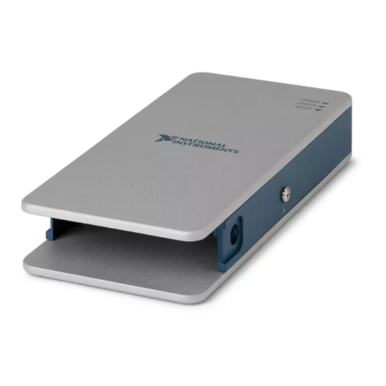
Figure 1-1 shows the cDAQ-9181/9191 chassis. Figure 1-1. cDAQ-9181/9191 Chassis (cDAQ-9191) Antenna and Antenna Connector POWER, STATUS, and ACTIVE LEDs Power Connector (cDAQ-9191) Wireless Signal Strength LEDs Ethernet Port, 10/100 and LINK/ACT LEDs Chassis Grounding Screw Reset Button Module Slot © National Instruments | 1-1... - Page 11 Chapter 1 Getting Started with the cDAQ Chassis Figure 1-2 shows the cDAQ-9184 chassis. Figure 1-2. cDAQ-9184 Chassis NI cDAQ-9184 NI CompactDAQ Chassis Grounding Screw Power Connector Installed C Series Module Reset Button Module Slots POWER, STATUS, and ACTIVE LEDs Ethernet Port, LINK/ACT and 10/100/1000 LEDs...
-
Page 12: Safety Guidelines
Product misuse can result in a hazard. You can compromise the safety protection built into the product if the product is damaged in any way. If the product is damaged, return it to National Instruments for repair. -
Page 13: Special Guidelines For Marine Applications
At the end of the product life cycle, all products must be sent to EU Customers a WEEE recycling center. For more information about WEEE recycling centers, National Instruments WEEE initiatives, and compliance with WEEE Directive 2002/96/EC on Waste and Electronic Equipment, visit ni.com/environment/... -
Page 14: Unpacking
NI cDAQ-9181/9184/9188/9191 User Manual Unpacking The cDAQ chassis ships in an antistatic package to prevent electrostatic discharge (ESD). ESD can damage several components on the device. Never touch the exposed pins of connectors. Caution To avoid ESD damage in handling the chassis, take the following precautions: •... - Page 15 The NI-DAQmx software is included on the disk shipped with your kit and is available for download at . The documentation for NI-DAQmx is available after ni.com/support installation from Start»All Programs»National Instruments»NI-DAQmx. Other NI documentation is available from ni.com/manuals (Optional) Mount the cDAQ chassis to a panel, wall, or DIN rail, or attach the desktop...
- Page 16 NI cDAQ-9181/9184/9188/9191 User Manual If you use shielded cabling to connect to a C Series module with a plastic Note connector, you must attach the cable shield to the chassis grounding terminal using 1.31 mm (16 AWG) or larger wire. Use shorter wire for better EMC performance.
- Page 17 Chapter 1 Getting Started with the cDAQ Chassis When operating the cDAQ-9181/9184/9188/9191 in hazardous locations, Caution you must use the power connector with a power supply rated for hazardous locations. The power supply included in the cDAQ-9181/9184/9188/9191 kit is not hazardous locations-certified.
- Page 18 NI cDAQ-9181/9184/9188/9191 User Manual Select a wireless network in one of the following ways: To connect to an existing wireless network, select Connect to wireless network • as the Wireless Mode. Figure 1-5. Connecting to a Wireless Network Before connecting to an enterprise network, you may first need to upload a certificate by clicking Certificate Management.
- Page 19 Chapter 1 Getting Started with the cDAQ Chassis To set a QoS Priority for the cDAQ chassis, click More Settings and select a Note priority from the list. The default QoS priority is Normal, which should be sufficient for most applications. Click the Save button.
- Page 20 NI cDAQ-9181/9184/9188/9191 User Manual 16. To add the chassis, double-click the NI MAX icon on the desktop to open MAX. Expand Devices and Interfaces»Network Devices. • If the wired or wireless connection is on your local subnet, the chassis automatically appears in the list of available devices.
- Page 21 Chapter 1 Getting Started with the cDAQ Chassis If you connected the cDAQ chassis directly to your computer, the setup time Note may be longer. Wait 30 to 60 seconds after the STATUS LED turns off, then click Refresh List. •...
-
Page 22: Wiring Power To The Cdaq Chassis
NI cDAQ-9181/9184/9188/9191 User Manual 19. If the cDAQ chassis is not reserved automatically, select the chassis and click the Reserve Chassis button. Refer to the Reserving the Chassis in MAX section for more information. 20. Self-test your chassis in MAX by expanding Devices and Interfaces, right-clicking NI cDAQ-<model number>, and selecting Self-Test. -
Page 23: Troubleshooting Chassis Connectivity
Chapter 1 Getting Started with the cDAQ Chassis Figure 1-9. Power Screw Terminal Connector Plug 1 V (Positive) Terminal Screw Connector Screw Flanges 2 C (Negative) Terminal Screw Do not tighten or loosen the terminal screws on the power connector while Caution the power is on. -
Page 24: Reserving The Chassis In Max
NI cDAQ-9181/9184/9188/9191 User Manual Figure 1-10. MAX Icons and States Recognized, but Disconnected from the Network, Unreserved, or Reserved by Another Host Recognized, Present, and Reserved on the Network For additional troubleshooting resources for the cDAQ chassis, refer to the Finding a Network DAQ Device in MAX topic in the Measurement &... -
Page 25: Mounting The Cdaq Chassis
Chapter 1 Getting Started with the cDAQ Chassis You can set or update the QoS Priority at any time when connected to a wireless network. In MAX, expand Devices and Interfaces»Network Devices, select the chassis, click the Network Settings tab, click More Settings, and select a priority. NI recommends setting the QoS Priority to Normal if you are connecting to an existing wireless network. -
Page 26: Using The Cdaq Chassis On A Desktop
NI cDAQ-9181/9184/9188/9191 User Manual Using the cDAQ Chassis on a Desktop You can use the cDAQ chassis on a desktop. cDAQ-9184/9188 users can also install an optional desktop mounting kit. Do not stack cDAQ chassis. Caution This transmitter must not be co-located or operated in Caution (cDAQ-9191) conjunction with any other antenna or transmitter. -
Page 27: Cdaq-9181/9191
You can then attach the cDAQ chassis to a wall or panel with the two holes or the four keyholes with M4, M5, No. 8, or No. 10 panhead screws. National Instruments does not provide these screws with the chassis. Refer to Figure 1-13 for panel mount accessory dimensions. - Page 28 NI cDAQ-9181/9184/9188/9191 User Manual Figure 1-12. Installing the cDAQ-9181/9191 Panel Mount Kit Figure 1-13. NI 9903 Panel Mount Accessory Dimensions POWER STATUS ACTIVE 101.6 mm 59.7 mm (4.00 in.) (2.35 in.) 38.1 mm (1.5 in.) 14.0 mm (0.55 in.) 118.1 mm (4.65 in.)
- Page 29 4.83 mm (0.190 in.) to go through the panel and into the back of the chassis, as shown in Figure 1-14. National Instruments does not provide these screws with the chassis. Refer to the specifications document for your cDAQ chassis for mounting dimensions.
-
Page 30: Cdaq-9184/9188
You can then attach the panel mount accessory to a wall or panel with the two holes or the four keyholes with M4, M5, No. 8, or No. 10 panhead screws. National Instruments does not provide these screws with the chassis. Refer to the documentation included with the panel mount kit for more detailed dimensions. - Page 31 Chapter 1 Getting Started with the cDAQ Chassis Figure 1-15. cDAQ-9184/9188 Panel Mount Dimensions and Installation 330.2 mm (13.00 in.) 88.1 mm (3.47 in.) 48.1 mm 28.1 mm (1.90 in.) (1.11 in.) 234.95 mm (9.25 in.) NI cDAQ-8184 NI CompactDAQ 88.1 mm (3.47 in.) 29.49 mm...
-
Page 32: Mounting The Cdaq Chassis On A Din Rail
Figure 1-16. The cDAQ-9184 uses two M4 or No. 8 flathead screws. The cDAQ-9188 uses two M4 or No. 8 panhead screws. National Instruments does not provide these screws with the chassis. Figure 1-16. Mounting the cDAQ Chassis Directly on a Flat Surface... -
Page 33: Cdaq-9181/9191
Chapter 1 Getting Started with the cDAQ Chassis cDAQ-9181/9191 The NI 9913 DIN rail mounting kit contains one clip for mounting the cDAQ chassis on a standard 35 mm DIN rail. Fasten the DIN rail clip to the cDAQ chassis using two FLH #6-32 ×... -
Page 34: Cdaq-9184/9188
NI cDAQ-9181/9184/9188/9191 User Manual Clip the chassis onto the DIN rail with the larger lip of the DIN rail clip positioned up, as shown in Figure 1-18. Figure 1-18. DIN Rail Clip Parts Locator Diagram DIN Rail Clip DIN Rail Spring DIN Rail Remove the module before removing the chassis from the DIN rail. -
Page 35: Cdaq Chassis Features
Chapter 1 Getting Started with the cDAQ Chassis Remove the module(s) before removing the chassis from the DIN rail. Caution cDAQ Chassis Features The cDAQ chassis features a chassis grounding screw, LEDs, reset button, Ethernet port, and power connector. The cDAQ-9188 chassis also features two PFI BNC connectors. The cDAQ-9191 chassis also features an antenna and antenna connector. - Page 36 NI cDAQ-9181/9184/9188/9191 User Manual Table 1-3. LED State/Chassis Status (Continued) Color LED State Chassis Status STATUS Yellow Chassis firmware booting, updating, or resetting to factory default Normal operation 3 Blinks Firmware image corrupted, update firmware through recovery utility. To download the recovery utility, go to and enter the Info Code ni.com/info...
-
Page 37: Ethernet Port
Chapter 1 Getting Started with the cDAQ Chassis Ethernet Port The cDAQ-9181/9191 chassis has one dual-speed RJ-45 Ethernet port, as shown in Figure 1-1. The cDAQ-9184/9188 chassis has one tri-speed RJ-45 Ethernet port, as shown in Figure 1-2 or 1-3. You can use a shielded straight through Category 5 Ethernet cable to connect one end to the RJ-45 Ethernet port on the chassis, and the other end directly to your computer or any network connection on the same subnet as your computer. -
Page 38: Ethernet Cabling
NI cDAQ-9181/9184/9188/9191 User Manual Ethernet Cabling Table 1-6 shows the shielded Ethernet cable wiring connections for both straight through and crossover cables. Table 1-6. Ethernet Cable Wiring Connections Connector 2 Connector 1 Straight Through Crossover white/orange white/orange white/green orange orange... -
Page 39: Reset Button
Chapter 1 Getting Started with the cDAQ Chassis Reset Button The cDAQ chassis is equipped with a reset button. Pressing the reset button results in the following chassis responses: • When pressed for less than five seconds, the chassis reboots with the current configuration. •... -
Page 40: Cables And Accessories
NI cDAQ-9181/9184/9188/9191 User Manual Cables and Accessories Table 1-8 contains information about cables and accessories available for the cDAQ chassis. For a complete list of cDAQ chassis accessories and ordering information, refer to the pricing section of the cDAQ-9181/9184/9188/9191 product page at ni.com... -
Page 41: Using The Cdaq Chassis
Network C Series Module National Instruments C Series modules provide built-in signal conditioning and screw terminal, spring terminal, BNC, D-SUB, or RJ-50 connectors. A wide variety of I/O types are available, allowing you to customize the cDAQ system to meet your application needs. -
Page 42: Parallel Versus Serial Dio Modules
NI cDAQ-9181/9184/9188/9191 User Manual Parallel versus Serial DIO Modules Digital module capabilities are determined by the type of digital signals that the module is capable of measuring or generating. • Serial digital modules are designed for signals that change slowly and are accessed by software-timed reads and writes. - Page 43 Chapter 1 Getting Started with the cDAQ Chassis PFI Signals—The PFI signals provide access to advanced features such as triggering, • synchronization, and counter/timers. You can also enable a programmable debouncing filter on each PFI signal that, when enabled, samples the input on each rising edge of a filter clock.
-
Page 44: Analog Input
Chapter 4, AI Start Trigger Signal, AI Reference Trigger Signal, and AI Pause Trigger Signal Refer to the sections for more information about the analog input trigger signals. © National Instruments | 2-1... -
Page 45: Analog Input Timing Signals
Chapter 2 Analog Input Analog Input Timing Signals The cDAQ chassis features the following analog input timing signals: AI Sample Clock Signal* • AI Sample Clock Timebase Signal • AI Start Trigger Signal* • AI Reference Trigger Signal* • AI Pause Trigger Signal* •... -
Page 46: Ai Convert Clock Signal Behavior For Analog Input Modules
NI cDAQ-9181/9184/9188/9191 User Manual AI Convert Clock Signal Behavior For Analog Input Modules Scanned Modules, Simultaneous Sample-and-Hold Modules, Sigma-Delta Modules, Refer to the Slow Sample Rate Modules sections for information about the AI Convert Clock signal and C Series analog input modules. -
Page 47: Slow Sample Rate Modules
Chapter 2 Analog Input When one or more sigma-delta modules are in an analog input task, the sigma-delta modules also provide the signal used as the AI Sample Clock. This signal is used to cause A/D conversion for other modules in the system, just as the AI Sample Clock does when a sigma-delta module is not being used. When sigma-delta modules are in an AI task, the chassis automatically issues a synchronization pulse to each sigma-delta modules that resets their ADCs at the same time. -
Page 48: Ai Start Trigger Signal
NI cDAQ-9181/9184/9188/9191 User Manual AI Start Trigger Signal Use the Start Trigger signal to begin a measurement acquisition. A measurement acquisition consists of one or more samples. If you do not use triggers, begin a measurement with a software command. Once the acquisition begins, configure the acquisition to stop in one of the following ways: •... -
Page 49: Using A Digital Source
Chapter 2 Analog Input Once the acquisition begins, the cDAQ chassis writes samples to the buffer. After the cDAQ chassis captures the specified number of pretrigger samples, the cDAQ chassis begins to look for the reference trigger condition. If the reference trigger condition occurs before the cDAQ chassis captures the specified number of pretrigger samples, the chassis ignores the condition. -
Page 50: Ai Pause Trigger Signal
NI cDAQ-9181/9184/9188/9191 User Manual AI Pause Trigger Signal You can use the Pause Trigger to pause and resume a measurement acquisition. The internal sample clock pauses while the external trigger signal is active and resumes when the signal is inactive. You can program the active level of the pause trigger to be high or low. -
Page 51: Analog Output
You can configure software-timed generations to simultaneously update • Only one simultaneous update task can run at a time • A hardware-timed AO task and a simultaneous update AO task cannot run at the same time © National Instruments | 3-1... -
Page 52: Hardware-Timed Generations
Chapter 3 Analog Output Hardware-Timed Generations With a hardware-timed generation, a digital hardware signal controls the rate of the generation. This signal can be generated internally on the chassis or provided externally. Hardware-timed generations have several advantages over software-timed acquisitions: •... -
Page 53: Analog Output Triggering Signals
NI cDAQ-9181/9184/9188/9191 User Manual Analog Output Triggering Signals Analog output supports two different triggering actions: AO Start Trigger and AO Pause Trigger. An analog or digital trigger can initiate these actions. Up to two C Series parallel digital input modules can be used in any chassis slot to supply a digital trigger. An analog trigger can be supplied by some C Series analog modules. -
Page 54: Routing Ao Sample Clock To An Output Terminal
Chapter 3 Analog Output Routing AO Sample Clock to an Output Terminal You can route AO Sample Clock to any output PFI terminal. AO Sample Clock is active high by default. AO Sample Clock Timebase Signal The AO Sample Clock Timebase (ao/SampleClockTimebase) signal is divided down to provide a source for AO Sample Clock. -
Page 55: Ao Pause Trigger Signal
NI cDAQ-9181/9184/9188/9191 User Manual AO Pause Trigger Signal Use the AO Pause Trigger signal (ao/PauseTrigger) to mask off samples in a DAQ sequence. When AO Pause Trigger is active, no samples occur, but AO Pause Trigger does not stop a sample that is in progress. -
Page 56: Using An Analog Source
Chapter 3 Analog Output Using an Analog Source Some C Series modules can generate a trigger based on an analog signal. In NI-DAQmx, this is called the Analog Comparison Event, depending on the trigger properties. When you use an analog trigger source, the samples are paused when the Analog Comparison Event signal is at a high or low level, depending on the trigger properties. -
Page 57: Digital Input/Output And Pfi
You can only do hardware timing in one direction at a time on a serial bidirectional module. To determine the capability of digital modules supported by the cDAQ chassis, go to ni.com/ and enter the Info Code info rdcdaq © National Instruments | 4-1... -
Page 58: Static Dio
Chapter 4 Digital Input/Output and PFI Static DIO Each of the DIO lines can be used as a static DI or DO line. You can use static DIO lines to monitor or control digital signals on some C Series modules. Each DIO line can be individually configured as a digital input (DI) or digital output (DO), if the C Series module being used allows such configuration. - Page 59 NI cDAQ-9181/9184/9188/9191 User Manual DI Sample Clock Signal Use the DI Sample Clock (di/SampleClock) signal to sample digital I/O on any slot using parallel digital modules, and store the result in the DI waveform acquisition FIFO. If the cDAQ chassis receives a DI Sample Clock signal when the FIFO is full, it reports an overflow error to the host software.
- Page 60 Chapter 4 Digital Input/Output and PFI Using an External Source You can route the following signals as DI Sample Clock: • Any PFI terminal • Analog Comparison Event (an analog trigger) You can sample data on the rising or falling edge of DI Sample Clock. Routing DI Sample Clock to an Output Terminal You can route DI Sample Clock to any output PFI terminal.
- Page 61 NI cDAQ-9181/9184/9188/9191 User Manual Routing DI Start Trigger to an Output Terminal You can route DI Start Trigger to any output PFI terminal. The output is an active high pulse. DI Reference Trigger Signal Use a reference trigger (di/ReferenceTrigger) signal to stop a measurement acquisition. To use a reference trigger, specify a buffer of finite size and a number of pretrigger samples (samples that occur before the reference trigger).
-
Page 62: Digital Input Filters
Chapter 4 Digital Input/Output and PFI Using an Analog Source Some C Series modules can generate a trigger based on an analog signal. In NI-DAQmx, this is called the Analog Comparison Event. When you use an analog trigger source, the acquisition stops on the first rising or falling edge of the Analog Comparison Event signal, depending on the trigger properties. -
Page 63: Getting Started With Di Applications In Software
NI cDAQ-9181/9184/9188/9191 User Manual In NI-DAQmx, the filter is programmed by setting the minimum pulse width, Tp , that will pass the filter, and is selectable in 25 ns increments. The appropriate Filter Clock is selected by the driver. Pulses of length less than 1/2 Tp will be rejected, and the filtering behavior of lengths between 1/2 Tp and 1 Tp are not defined because they depend on the phase of the Filter Clock relative to the input signal. -
Page 64: Digital Output
Chapter 4 Digital Input/Output and PFI Change detection acquisitions can be buffered or nonbuffered: Nonbuffered Change Detection Acquisition—In a nonbuffered acquisition, data is • transferred from the cDAQ chassis directly to a PC buffer. Buffered Change Detection Acquisition—A buffer is a temporary storage in computer •... - Page 65 NI cDAQ-9181/9184/9188/9191 User Manual Hardware-Timed Generations With a hardware-timed generation, a digital hardware signal controls the rate of the generation. This signal can be generated internally on the chassis or provided externally. Hardware-timed generations have several advantages over software-timed acquisitions: •...
-
Page 66: Digital Output Triggering Signals
Chapter 4 Digital Input/Output and PFI Digital Output Triggering Signals Digital output supports two different triggering actions: DO Start Trigger and DO Pause Trigger. A digital or analog trigger can initiate these actions. Any PFI terminal can supply a digital trigger, and some C Series analog modules can supply an analog trigger. - Page 67 NI cDAQ-9181/9184/9188/9191 User Manual DO Sample Clock Timebase Signal The DO Sample Clock Timebase (do/SampleClockTimebase) signal is divided down to provide a source for DO Sample Clock. DO Sample Clock Timebase can be generated from external or internal sources, and is not available as an output from the chassis.
- Page 68 Chapter 4 Digital Input/Output and PFI When you generate digital output signals, the generation pauses as soon as the pause trigger is asserted. If the source of the sample clock is the onboard clock, the generation resumes as soon as the pause trigger is deasserted, as shown in Figure 4-5. Figure 4-5.
-
Page 69: Getting Started With Do Applications In Software
NI cDAQ-9181/9184/9188/9191 User Manual Getting Started with DO Applications in Software You can use the cDAQ chassis in the following digital output applications: • Single-point (on-demand) generation • Finite generation • Continuous generation For more information about programming digital output applications and triggers in software, refer the LabVIEW Help or to the NI-DAQmx Help. - Page 70 Chapter 4 Digital Input/Output and PFI Assume that an input terminal has been low for a long time. The input terminal then changes from low to high, but glitches several times. When the Filter Clock has sampled the signal high on N consecutive edges, the low-to-high transition is propagated to the rest of the circuit.
-
Page 71: Counters
(Embedded Ctrn) for use in what are traditionally two-counter measurements and generations. The embedded counters cannot be programmed independent of the main counter; signals from the embedded counters are not routable. © National Instruments | 5-1... -
Page 72: Counter Timing Engine
Chapter 5 Counters Counter Timing Engine Unlike analog input, analog output, digital input, and digital output, the cDAQ chassis counters do not have the ability to divide down a timebase to produce an internal counter sample clock. For sample clocked operations, an external signal must be provided to supply a clock source. The source can be any of the following signals: •... -
Page 73: Counter Input Applications
NI cDAQ-9181/9184/9188/9191 User Manual Table 5-1. Counter Timing Measurements (Continued) Implicit Sample Clocked Measurement Timing Support Timing Support Buffered Position Buffered Two-Signal Edge Separation Counter Input Applications The following sections list the various counter input applications available on the cDAQ chassis: Counting Edges •... -
Page 74: Buffered (Sample Clock) Edge Counting
Chapter 5 Counters You also can use a pause trigger to pause (or gate) the counter. When the pause trigger is active, the counter ignores edges on its Source input. When the pause trigger is inactive, the counter counts edges normally. You can route the pause trigger to the Gate input of the counter. -
Page 75: Controlling The Direction Of Counting
NI cDAQ-9181/9184/9188/9191 User Manual Controlling the Direction of Counting In edge counting applications, the counter can count up or down. You can configure the counter to do the following: • Always count up • Always count down • Count up when the Counter 0 B input is high; count down when it is low... -
Page 76: Single Pulse-Width Measurement
Chapter 5 Counters Single Pulse-Width Measurement With single pulse-width measurement, the counter counts the number of edges on the Source input while the Gate input remains active. When the Gate input goes inactive, the counter stores the count in the FIFO and ignores other edges on the Gate and Source inputs. Software then reads the stored count. -
Page 77: Pulse Measurement
NI cDAQ-9181/9184/9188/9191 User Manual The counter counts the number of edges on the Source input while the Gate input remains active. On each sample clock edge, the counter stores the count in the FIFO of the last pulse width to complete. -
Page 78: Single Pulse Measurement
Chapter 5 Counters Single Pulse Measurement Single (on-demand) pulse measurement is equivalent to two single pulse-width measurements on the high (H) and low (L) ticks of a pulse, as shown in Figure 5-8. Figure 5-8. Single (On-Demand) Pulse Measurement Counter Armed Gate Source Latched... -
Page 79: Semi-Period Measurement
NI cDAQ-9181/9184/9188/9191 User Manual Figure 5-10 shows an example of a sample clocked buffered pulse measurement. Figure 5-10. Sample Clocked Buffered Pulse Measurement Counter Armed Gate Source Sample Clock Buffer If a pulse does not occur between sample clocks, an overrun error occurs. -
Page 80: Implicit Buffered Semi-Period Measurement
Chapter 5 Counters Implicit Buffered Semi-Period Measurement In implicit buffered semi-period measurements, on each edge of the Gate signal, the counter stores the count in the FIFO. The STC3 transfers the sampled values to host memory using a high-speed data stream. The counter begins counting when it is armed. -
Page 81: Frequency Measurement
NI cDAQ-9181/9184/9188/9191 User Manual Frequency Measurement You can use the counters to measure frequency in several different ways. Refer to the following sections for information about cDAQ chassis frequency measurement options: Low Frequency with One Counter • High Frequency with Two Counters •... -
Page 82: High Frequency With Two Counters
Chapter 5 Counters High Frequency with Two Counters For high frequency measurements with two counters, you measure one pulse of a known width using your signal and derive the frequency of your signal from the result. Counter 0 is always paired with Counter 1. Counter 2 is always paired with Note Counter 3. -
Page 83: Sample Clocked Buffered Frequency Measurement
NI cDAQ-9181/9184/9188/9191 User Manual You can route the signal to measure to the Source input of Counter 0, as shown in Figure 5-14. Assume this signal to measure has frequency fx. NI-DAQmx automatically configures Counter 0 to generate a single pulse that is the width of N periods of the source input signal. -
Page 84: Choosing A Method For Measuring Frequency
Chapter 5 Counters Figure 5-15. Sample Clocked Buffered Frequency Measurement (Averaging) Counter Armed Gate (fx) Source (fk) Sample Clock T1 T2 T1 T2 T1T2 Buffer 2 10 2 10 When CI.Freq.EnableAveraging is set to false, the frequency measurement returns the frequency of the pulse just before the sample clock. - Page 85 NI cDAQ-9181/9184/9188/9191 User Manual Divide down (N) is the integer to divide down measured frequency, only used in large range two counters is the sample clock rate, only used in sample clocked frequency measurements Here is how these variables apply to each method, summarized in Table 5-2.
-
Page 86: Which Method Is Best
Chapter 5 Counters Which Method Is Best? This depends on the frequency to be measured, the rate at which you want to monitor the frequency and the accuracy you desire. Take for example, measuring a 50 kHz signal. Assuming that the measurement times for the sample clocked (with averaging) and two counter frequency measurements are configured the same, Table 5-3 summarizes the results. - Page 87 NI cDAQ-9181/9184/9188/9191 User Manual From this, you can see that while the measurement time for one counter is shorter, the accuracy is best in the sample clocked and two counter large range measurements. For another example, Table 5-4 shows the results for 5 MHz.
-
Page 88: Period Measurement
Chapter 5 Counters • Measuring a large range of frequencies with two counters measures high and low frequency signals accurately. However, it requires two counters, and it has a variable sample time and variable error % dependent on the input signal. Table 5-5 summarizes some of the differences in methods of measuring frequency. -
Page 89: Position Measurement
NI cDAQ-9181/9184/9188/9191 User Manual Position Measurement You can use the counters to perform position measurements with quadrature encoders or two-pulse encoders. You can measure angular position with X1, X2, and X4 angular encoders. Linear position can be measured with two-pulse encoders. You can choose to do either a single point (on-demand) position measurement or a buffered (sample clock) position measurement. -
Page 90: Channel Z Behavior
Chapter 5 Counters X4 Encoding—Similarly, the counter increments or decrements on each edge of • channels A and B for X4 encoding. Whether the counter increments or decrements depends on which channel leads the other. Each cycle results in four increments or decrements, as shown in Figure 5-19. -
Page 91: Measurements Using Two Pulse Encoders
NI cDAQ-9181/9184/9188/9191 User Manual Measurements Using Two Pulse Encoders The counter supports two pulse encoders that have two channels—channels A and B. The counter increments on each rising edge of channel A. The counter decrements on each rising edge of channel B, as shown in Figure 5-21. -
Page 92: Single Two-Signal Edge-Separation Measurement
Chapter 5 Counters After the counter has been armed and an active edge occurs on the Aux input, the counter counts the number of rising (or falling) edges on the Source. The counter ignores additional edges on the Aux input. The counter stops counting upon receiving an active edge on the Gate input. -
Page 93: Sample Clocked Buffered Two-Signal Separation Measurement
NI cDAQ-9181/9184/9188/9191 User Manual the count in the FIFO. On the next active edge of the Gate signal, the counter begins another measurement. The STC3 transfers the sampled values to host memory using a high-speed data stream. Figure 5-24 shows an example of an implicit buffered two-signal edge-separation measurement. -
Page 94: Counter Output Applications
Chapter 5 Counters Counter Output Applications The following sections list the various counter output applications available on the cDAQ chassis: Simple Pulse Generation • Pulse Train Generation • Frequency Generation • Frequency Division • Pulse Generation for ETS • Simple Pulse Generation Refer to the following sections for more information about the cDAQ chassis simple pulse generation options: Single Pulse Generation... -
Page 95: Single Pulse Generation With Start Trigger
NI cDAQ-9181/9184/9188/9191 User Manual Single Pulse Generation with Start Trigger The counter can output a single pulse in response to one pulse on a hardware Start Trigger signal. The pulse appears on the Counter n Internal Output signal of the counter. -
Page 96: Retriggerable Pulse Or Pulse Train Generation
Chapter 5 Counters Figure 5-28. Finite Pulse Train Generation: Four Ticks Initial Delay, Four Pulses Counter Armed Source Enablex Ctrx Retriggerable Pulse or Pulse Train Generation The counter can output a single pulse or multiple pulses in response to each pulse on a hardware Start Trigger signal. -
Page 97: Continuous Pulse Train Generation
NI cDAQ-9181/9184/9188/9191 User Manual Figure 5-30 shows the same pulse train with CO.EnableInitalDelayOnRetrigger set to the default False. Figure 5-30. Retriggerable Single Pulse Generation False Counter Load Values 4 3 2 1 0 2 1 0 4 3 2 1 0 2 1 0... -
Page 98: Buffered Pulse Train Generation
Chapter 5 Counters Continuous pulse train generation is sometimes called frequency division. If the high and low pulse widths of the output signal are M and N periods, then the frequency of the Counter n Internal Output signal is equal to the frequency of the Source input divided by M + N. Default Counter/Timer Routing For information about connecting counter signals, refer to the section. -
Page 99: Continuous Buffered Implicit Pulse Train Generation
NI cDAQ-9181/9184/9188/9191 User Manual Figure 5-32. Finite Implicit Buffered Pulse Train Generation SOURCE Counter Armed Continuous Buffered Implicit Pulse Train Generation This function generates a continuous train of pulses with variable idle and active times. Instead of generating a set number of data samples and stopping, a continuous generation continues until you stop the operation. -
Page 100: Continuous Buffered Sample Clocked Pulse Train Generation
Chapter 5 Counters Figure 5-33. Finite Buffered Sample Clocked Pulse Train Generation Counter Armed Sample Clock Counter 2 1 0 1 0 1 0 1 2 1 0 2 1 0 2 1 0 2 1 0 1 0 0 2 1 0 2 1 Load Values Source There are several different methods of continuous generation that control what data is written. -
Page 101: Frequency Division
NI cDAQ-9181/9184/9188/9191 User Manual Figure 5-34 shows a block diagram of the frequency generator. Figure 5-34. Frequency Generator Block Diagram Frequency Output ÷ 20 MHz Timebase Timebase Frequency Generator FREQ OUT 100 kHz Timebase Divisor (1–16) The frequency generator generates the Frequency Output signal. The Frequency Output signal is the Frequency Output Timebase divided by a number you select from 1 to 16. -
Page 102: Pulse Generation For Ets
Chapter 5 Counters Pulse Generation for ETS In the equivalent time sampling (ETS) application, the counter produces a pulse on the output a specified delay after an active edge on Gate. After each active edge on Gate, the counter cumulatively increments the delay between the Gate and the pulse on the output by a specified amount. -
Page 103: Counter N Source Signal
NI cDAQ-9181/9184/9188/9191 User Manual Counter n HW Arm Signal • Counter n Sample Clock Signal • Counter n Internal Output Signal • Counter n TC Signal • Frequency Output Signal • In this section, n refers to the cDAQ chassis Counter 0, 1, 2, or 3. For example, Counter n Source refers to four signals—Counter 0 Source (the source input to Counter 0), Counter 1 Source (the... -
Page 104: Routing Counter N Source To An Output Terminal
Chapter 5 Counters In addition, TC or Gate from a counter can be routed to a different counter source. Some of these options may not be available in some driver software. Refer to the Device Routing in MAX topic in the NI-DAQmx Help or the LabVIEW Help for more information about available routing options. -
Page 105: Counter N Aux Signal
NI cDAQ-9181/9184/9188/9191 User Manual Counter n Aux Signal The Counter n Aux signal indicates the first edge in a two-signal edge-separation measurement. Routing a Signal to Counter n Aux Each counter has independent input selectors for the Counter n Aux signal. Any of the following signals can be routed to the Counter n Aux input: •... -
Page 106: Routing Signals To Counter N Hw Arm Input
Chapter 5 Counters other applications, such as single pulse-width measurement, the counter begins waiting for the Gate signal when it is armed. Counter output operations can use the arm signal in addition to a start trigger. Software can arm a counter or configure counters to be armed on a hardware signal. Software calls this hardware signal the Arm Start Trigger. -
Page 107: Using An External Source
NI cDAQ-9181/9184/9188/9191 User Manual Several other internal signals can be routed to Counter n Sample Clock through internal routes. Refer to Device Routing in MAX in the NI-DAQmx Help or the LabVIEW Help for more information. Using an External Source You can route any of the following signals as Counter n Sample Clock: •... -
Page 108: Counter Triggering
Chapter 5 Counters measurements and generations. Refer to Physical Channels in the NI-DAQmx Help or the LabVIEW Help for a list of default PFI lines for counter functions. Counter Triggering Counters support three different triggering actions: Arm Start Trigger—To begin any counter input or output function, you must first enable, •... -
Page 109: Prescaling
NI cDAQ-9181/9184/9188/9191 User Manual Prescaling Prescaling allows the counter to count a signal that is faster than the maximum timebase of the counter. The cDAQ chassis offers 8X and 2X prescaling on each counter (prescaling can be disabled). Each prescaler consists of a small, simple counter that counts to eight (or two) and rolls over. -
Page 110: External Or Internal Source Less Than 20 Mhz
Chapter 5 Counters External or Internal Source Less than 20 MHz With an external or internal source less than 20 MHz, the module generates a delayed Source signal by delaying the Source signal by several nanoseconds. The chassis synchronizes signals on the rising edge of the delayed Source signal, and counts on the following rising edge of the source, as shown in Figure 5-39. -
Page 111: Digital Routing And Clock Generation
Routes tab in MAX. Clock Routing Figure 6-1 shows the clock routing circuitry of the cDAQ chassis. Figure 6-1. Clock Routing Circuitry 80 MHz Timebase Onboard 80 MHz ÷ 20 MHz Timebase Oscillator ÷ 100 kHz Timebase © National Instruments | 6-1... -
Page 112: 80 Mhz Timebase
Chapter 6 Digital Routing and Clock Generation 80 MHz Timebase You can use the 80 MHz Timebase as the Source input to the 32-bit general-purpose counter/timers. The 80 MHz Timebase can be generated from the onboard oscillator. 20 MHz Timebase The 20 MHz Timebase normally generates many of the AI and AO timing signals. - Page 113 This device has been evaluated for and shown compliant with the IC Radio Frequency (RF) Exposure limits. The device should be used in such a manner such that the potential for human contact during normal operation is minimized. © National Instruments | A-1...
- Page 114 Appendix A cDAQ-9191 Regulatory Information This device has been certified for use in Canada. Status of the listing in the Industry Canada’s REL (Radio Equipment List) can be found at the following web address: http://www.ic.gc.ca/app/sitt/reltel/srch/nwRdSrch.do?lang=eng Additional Canadian information on RF exposure also can be found at the following web address: http://www.ic.gc.ca/eic/site/smt-gst.nsf/eng/sf08792.html Canada, avis d’Industry Canada (IC)
- Page 115 NI cDAQ-9181/9184/9188/9191 User Manual EU Regulatory Statements National Instruments tímto prohlašuje, že tento NI cDAQ-9191 je ve Česky [Czech] shodě se základními požiadavkami a dalšími příslušnými ustanoveními směrnice 1999/5/ES. Undertegnede National Instruments erklćrer herved, at fřlgende udstyr Dansk [Danish] NI cDAQ-9191 overholder de vćsentlige krav og řvrige relevante krav i direktiv 1999/5/EF.
- Page 116 [Swedish] överensstämmelse med de väsentliga egenskapskrav och övriga relevanta bestämmelser som framgår av direktiv 1999/5/EG. Hér með lýsir National Instruments yfir því að NI cDAQ-9191 er í Íslenska [Icelandic] samræmi við grunnkröfur og aðrar kröfur, sem gerðar eru í tilskipun 1999/5/EC.
- Page 117 NI cDAQ-9181/9184/9188/9191 User Manual Taiwan R.O.C. Brasil – Aviso da Anatel Modelo: SX-10WG 1047-14-9143 *0107898581340997* ( 0 1 ) 0 7 8 9 8 5 8 1 3 4 0 9 9 7 ( 0 1 ) 0 7 8 9 8 5 8 1 3 4 0 9 9 7 Este equipamento opera em caráter secundário, isto é, não tem direito a proteção contra...
-
Page 118: Related Documentation
NI-DAQmx 16.0 or later. cDAQ Chassis Documentation The NI cDAQ-9181 Quick Start, NI cDAQ-9184/9188 Quick Start, or NI cDAQ-9191 Quick Start, packaged with your cDAQ chassis, describes how to install your NI-DAQmx for Windows software, how to install the cDAQ chassis and C Series module, and how to confirm that your device is operating properly. - Page 119 NI-DAQmx The NI-DAQmx Readme lists which devices, ADEs, and NI application software are supported by this version of NI-DAQmx. Select Start»All Programs»National Instruments» NI-DAQmx»NI-DAQ Readme. The NI-DAQmx Help contains API overviews, general information about measurement concepts, key NI-DAQmx concepts, and common applications that are applicable to all programming environments.
- Page 120 Select Start»All Programs»National Instruments»NI-DAQmx»NI-DAQmx Help. The NI-DAQmx C Reference Help describes the NI-DAQmx Library functions, which you can use with National Instruments data acquisition devices to develop instrumentation, acquisition, and control applications. Select Start»All Programs»National Instruments»NI-DAQmx» Text-Based Code Support»NI-DAQmx C Reference Help.
- Page 121 Appendix B Where to Go from Here .NET Languages without NI Application Software With the Microsoft .NET Framework, you can use NI-DAQmx to create applications using Visual C# and Visual Basic .NET without Measurement Studio. Refer to the NI-DAQmx Readme for specific versions supported. Training Courses If you need more help getting started developing an application with NI products, NI offers training courses.
- Page 122 System Integration—If you have time constraints, limited in-house technical resources, or • other project challenges, National Instruments Alliance Partner members can help. To learn more, call your local NI office or visit ni.com/alliance © National Instruments | C-1...
- Page 123 Appendix C NI Services Training and Certification—The NI training and certification program is the most • effective way to increase application development proficiency and productivity. Visit for more information. ni.com/training – The Skills Guide assists you in identifying the proficiency requirements of your current application and gives you options for obtaining those skills consistent with your time and budget constraints and personal learning preferences.
- Page 124 AO Start Trigger, 3-4 uninstalling, 1-31 ANSI C documentation, B-3 unpacking, 1-5 antenna, 1-30 using, 1-32 applications cDAQ module interface, 1-33 counter input, 5-3 channel Z behavior, 5-20 counter output, 5-24 chassis grounding screw, 1-26 © National Instruments | I-1...
- Page 125 Index choosing frequency measurement, 5-14 digital I/O configuration, 1-5 change detection event, 4-7 connector configuration for NI 9401, 4-13 PFI BNC, 1-30 digital input, 4-2 power, 1-30 digital output, 4-8 continuous pulse train generation, 5-27 parallel versus serial DIO modules, 4-1 controlling counting direction, 5-3 static DIO, 4-2 counter signals...
- Page 126 NI cDAQ-9181/9184/9188/9191 User Manual encoding getting started X1, 5-19 AI applications in software, 2-7 X2, 5-19 AO applications in software, 3-6 X4, 5-20 DI applications in software, 4-7 equivalent time sampling, 5-32 DO applications in software, 4-13 Ethernet guidelines, electromagnetic...
- Page 127 Index single semi-period, 5-9 single two-signal edge-separation, 5-22 QoS priority, 1-15 two-signal edge-separation, 5-21 quadrature encoders, 5-19 using quadrature encoders, 5-19 using two pulse encoders, 5-21 measuring rebooting, 1-30 high frequency with two counters, 5-12 reciprocal frequency measurement, 5-12 large range of frequencies using two regulatory information, A-1 counters, 5-12 related documentation, B-1...
- Page 128 NI cDAQ-9181/9184/9188/9191 User Manual trigger arm start, 5-38 pause, 5-38 start, 5-38 troubleshooting chassis connectivity, 1-14 two-signal edge-separation measurement, 5-21 buffered, 5-22 single, 5-22 uninstalling, 1-31 unpacking, 1-5 using the cDAQ chassis, 1-32 wireless networks, 1-12 QoS priority, 1-15 regulatory information, A-1...
Need help?
Do you have a question about the NI cDAQ-9181 and is the answer not in the manual?
Questions and answers