
Related Manuals for National Instruments cDAQ-9170


Summary of Contents for National Instruments cDAQ-9170
- Page 1 9173/9177 User Manual 2025-02-20 Tél. 01 47 95 99 71 e-mail : ni@es-france.com ES France - Département NI Fax. 01 47 01 16 22 Site Web : www.es-france.com 127 rue de Buzenval BP 26 - 92380 Garches...
-
Page 2: Table Of Contents
Components of a cDAQ-9170/9173/9177 System ........ - Page 3 User Manual Mounting the cDAQ Chassis on a Desktop ........48 Dimensions .
- Page 4 User Manual DI Pause Trigger Signal ..........76 Digital Input Filters .
- Page 5 User Manual Counter n Gate Signal ........... 126 Counter n Aux Signal .
-
Page 6: Welcome To The User Manual
User Manual User Manual The cDAQ-9170/9173/9177 User Manual provides detailed descriptions of the product functionality and the step by step processes for use. Looking for Something Else? For information not found in the User Manual for your product, such as specifications and API reference, browse Related Information . -
Page 7: System Health Monitoring
Overview Overview The one-slot NI cDAQ-9170, four-slot NI cDAQ-9173, and eight-slot NI cDAQ-9177 USB chassis are designed for use with C Series modules. The cDAQ chassis are capable of measuring a broad range of analog and digital I/O signals using a USB-C interface. For module specifications, refer to the documentation included with your C Series module (s) or go to ni.com/docs. - Page 8 Time triggers and timestamps can be specified in Host Time or I/O Device Time, depending on the needs of your application. • I/O Device Time—The time the cDAQ-9170/9173/9177 uses internally. This time is determined by the network configuration and is shared by all 802.1AS network- synchronized devices on your subnet.
- Page 9 Overview Firmware Firmware can be updated through the Hardware Configuration Utility, NI MAX, or the web interface to the chassis. For cDAQ firmware information and updates, visit ni.com/ info and enter the Info Code cdaqfw. © National Instruments Tél. 01 47 95 99 71 e-mail : ni@es-france.com...
-
Page 10: Driver Support
Table 1. Earliest Driver Version Support Driver Name Earliest Version Support NI-DAQmx cDAQ-9173/77 2025 Q1, cDAQ-9170 2025 Q2 ni.com Tél. 01 47 95 99 71 e-mail : ni@es-france.com ES France - Département NI Fax. 01 47 01 16 22 Site Web : www.es-france.com... -
Page 11: Components Of A Cdaq-9170/9173/9177 System
Components of a cDAQ-9170/9173/9177 cDAQ-9170/9173/9177 System System cDAQ-9170/9173/9177 is designed for use in a system that might require hardware, drivers, and software to optimize cDAQ-9170/9173/9177 for your application. Use the minimum required cDAQ-9170/9173/9177 system components as a starting point for building your system. - Page 12 C Series modules. Note For optimal performance, use the most current version of NI-DAQmx with the cDAQ-9170/9173/9177. You can find the NI- DAQmx driver requirements in the NI-DAQmx Release Notes . NI Applications NI-DCPower offers driver support for the following applications: •...
-
Page 13: Part Numbers For Recommended Cables And Accessories
Part Numbers for Recommended Cables and Part Numbers for Recommended Cables and Accessories Accessories Use part numbers to purchase the cables and the accessories for optimizing the performance of cDAQ-9170/9173/9177. Table 3. Part numbers for Recommended Power Connector Accessories Accessory Description Part number... - Page 14 Part Numbers for Recommended Cables and Accessories Accessory Description Part number Locking USB cable, (2 m length) 758787-01 Table 6. Part Numbers for Recommended Power Supplies Accessory Description Part number 24 VDC, 5 A, 120 W Desktop PS-10 782698-01 Power Supply 12 VDC, 1.25 A, 100-240 VAC PS-9 780703-01...
- Page 15 Mounting the cDAQ Chassis on a Panel with a Panel Mounting Kit Related information: • CompactDAQ System Accessory Compatibility Guide © National Instruments Tél. 01 47 95 99 71 e-mail : ni@es-france.com ES France - Département NI Fax. 01 47 01 16 22 Site Web : www.es-france.com...
-
Page 16: Theory Of Operation
Theory of Operation Theory of Operation The cDAQ-9170/9173/9177 USB-C chassis are designed for use with C Series modules. The cDAQ chassis are capable of measuring a broad range of analog and digital I/O signals and sensors. The cDAQ system consists of three parts—C Series module(s), the cDAQ module interface, and the NI ASIC—as shown in Figure 2. - Page 17 C Series Module C Series Module National Instruments C Series modules provide built-in signal conditioning and connectivity, such as screw terminal, spring terminal, BNC, DSUB, or RJ-50 connectors. A wide variety of I/O types are available, allowing you to customize the cDAQ system to meet your application needs.
- Page 18 ◦ Digital Input Triggering Signals ◦ Digital Output Triggering Signals • Independent Data Streams—The cDAQ-9170 chassis supports six independent high-speed data streams, which allow for up to seven simultaneous hardware- timed tasks, such as analog input, analog output, buffered counter/timers, and hardware-timed digital input/output.
- Page 19 Theory of Operation programmable debouncing filter on each PFI signal that, when enabled, samples the input on each rising edge of a filter clock. PFI signals are available through parallel digital input and output modules installed in up to two chassis slots and through the two PFI terminals provided on the cDAQ-9177 chassis.
-
Page 20: Examples
Examples NI installs example code with your software or driver that demonstrates the functionality of cDAQ-9170/9173/9177. Use these examples to learn about the product or accelerate your own application development. To locate NI software examples, go to ni.com/info and enter the Info Code daqmxexp. - Page 21 NI-DAQmx examples are available from the software download and from ni.com/ support. To run examples without the device installed, use an NI-DAQmx simulated device. NI-DAQmx installs examples for cDAQ-9170/9173/9177 in the following software: • LabVIEW or LabWindows/CVI • SignalExpress • ANSI C •...
-
Page 22: Front Panel
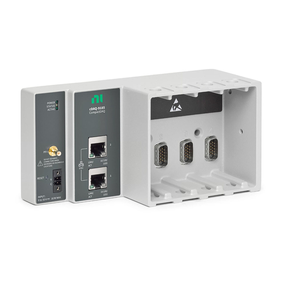
Front Panel cDAQ-9170/9173/9177 cDAQ-9170/9173/9177 Front Panel Front Panel Refer to the front panel diagram to understand the connectors, LEDs, and other features of the cDAQ-9170/9173/9177. Figure 3. cDAQ-9170/9173/9177 Front Panel POWER STATUS ACTIVE cDAQ-9183 CompactDAQ ni.com/91xx-setup DO NOT SEPARATE... -
Page 23: Usb-C Port
USB connection is not established/suspend USB-C Port USB-C Port The cDAQ-9170/9173/9177 chassis have a USB-C port. You can use a strain relieved USB-C cable to network your chassis to a computer host or a NI Linux Real-Time controller. Related information: ©... -
Page 24: Usb Cabling
The power supply included in the cDAQ-9170/9173/9177 kit is intended only for desktop use. For all other applications use the included 2-position power connector plug and a power supply rated for your application power requirements. -
Page 25: Chassis Grounding Screw
Front Panel Note Only the 8 slot cDAQ-9177 has PFI slots. Chassis Grounding Screw Chassis Grounding Screw Notice To ensure the specified EMC performance, the cDAQ chassis must be connected to the grounding electrode system of your facility using the chassis ground terminal. -
Page 26: Kit Contents
Kit Contents Kit Contents Kit Contents Items in your cDAQ chassis kit: • cDAQ-9170/9173/9177 chassis • Documentation • Power supply • USB-C Cable • Screwdriver ni.com Tél. 01 47 95 99 71 e-mail : ni@es-france.com ES France - Département NI Fax. -
Page 27: Safety Guidelines
Safety Guidelines Safety Guidelines Caution Do not operate the cDAQ-9170/9173/9177 in a manner not specified in this user manual. Product misuse can result in a hazard. You can compromise the safety protection built into the product if the product is damaged in any way. -
Page 28: Electromagnetic Compatibility Guidelines
Electromagnetic Compatibility Guidelines Electromagnetic Compatibility Guidelines Electromagnetic Compatibility Guidelines This product was tested and complies with the regulatory requirements and limits for electromagnetic compatibility (EMC) stated in the product specifications. These requirements and limits provide reasonable protection against harmful interference when the product is operated in the intended operational electromagnetic environment. -
Page 29: Setting Up The Cdaq-9170/9173/9177
Setting up the cDAQ-9170/9173/9177 Setting up the Setting up the cDAQ-9170/9173/9177 cDAQ-9170/9173/9177 Confirm your kit contents, install the cDAQ-9170/9173/9177 chassis, and prepare it for use. The cDAQ chassis and C Series module(s) are packaged separately. Unpacking Unpacking The cDAQ chassis ships in an antistatic package to prevent electrostatic discharge (ESD). - Page 30 Setting up the cDAQ-9170/9173/9177 Figure 4. Installation Supply List 1. Host Computer Running Windows 2. Application Software, such as LabVIEW, if not already installed 3. NI-DAQmx Driver (packaged with the cDAQ chassis) 4. cDAQ-9170/9173/9177 Chassis 5. C Series Module(s) 6. Strain relieved USB-C cable 7.
-
Page 31: Installing The Cdaq Chassis
Complete the following steps to install the cDAQ-9170/9173/9177. The cDAQ chassis and C Series module(s) are packaged separately. Refer to the cDAQ-9170/9173/9177 front panel diagram while completing the following assembly steps. 1. Install the application software (if applicable), as described in the installation instructions that accompany your software. - Page 32 Setting up the cDAQ-9170/9173/9177 Note If you use shielded cabling to connect to a C Series module with a plastic connector, you must attach the cable shield to the chassis grounding terminal using 1.31 mm (16 AWG) or larger wire. Use shorter wire for better EMC performance.
- Page 33 When operating the cDAQ-9170 in hazardous locations, you must use the power connector with an external power supply rated for hazardous locations. The power supply included in the cDAQ-9170 kit is intended only for desktop use. For all other applications use the included 2-position power connector plug and a power supply rated for your application power requirements.
-
Page 34: Wiring External Power To The Cdaq Chassis
Setting up the cDAQ-9170/9173/9177 Wiring External Power to the cDAQ Chassis Wiring External Power to the cDAQ Chassis Complete the following steps to connect a power source to the cDAQ chassis. Notice To ensure the specified EMC performance, do not connect the power input to a DC mains supply or to any supply requiring a connecting cable longer than 3 m (10 ft). -
Page 35: Verifying Installation In Hwcu/Max
1. Open Hardware Configuration Utility. The cDAQ-9170/9173/9177 appears in the system pane automatically. If the cDAQ-9170/9173/9177 is not shown in the system pane, click the + (Add Hardware) button, select the chassis from the Discovered devices, and click Add. © National Instruments Tél. -
Page 36: Verifying The Installation With Max
Troubleshooting area of the configuration pane, and click Self-test. Hardware Configuration Utility reports when it has validated the hardware setup. What Do I Do If the cDAQ-9170/9173/9177 Does Not Appear in Hardware Configuration Utility? 1. Click the refresh button ( ) to refresh the connection between the hardware and the software. - Page 37 Setting up the cDAQ-9170/9173/9177 ◦ Check the box that corresponds to your chassis in the Hostname column. ◦ If you know the chassis IP address, such as 192.168.0.2, enter it into the Add Device Manually field of the Find Network NI-DAQmx Devices window, and click the + button.
- Page 38 Setting up the cDAQ-9170/9173/9177 Reserve Chassis button. Refer to the Reserving the Chassis in MAX section for more information. 5. Self-test your chassis in MAX by expanding Devices and Interfaces, right-clicking NI cDAQ-<model number>, and selecting Self-Test. Self-test performs a brief test to determine successful chassis installation.
- Page 39 Troubleshooting Chassis Connectivity in MAX If your cDAQ chassis is not discovered or becomes disconnected from the network, try the following suggestions. If the cDAQ-9170/9173/9177 is not listed under Device and Interfaces » Network Device, complete the following steps. 1. Power off the system.
- Page 40 Setting up the cDAQ-9170/9173/9177 cDAQ-9170/9173/9177 Connected Directly to Your Computer is Not Discovered in For the initial configuration, the host computer must be set to obtain an IP address automatically since the cDAQ-9170/9173/9177 relies on Link-Local addressing to communicate with the host computer. The procedure for configuring your computer to obtain an IP address automatically varies depending on your operating system.
-
Page 41: Removing Modules From The Cdaq-9170/9173/9177
Removing Modules from the cDAQ-9170/9173/9177 Removing Modules from the Removing Modules from the cDAQ-9170/9173/9177 cDAQ-9170/9173/9177 Complete the following steps to remove a C Series module from the cDAQ chassis. 1. Make sure that no I/O-side power is connected to the module. If the system is in a nonhazardous location, the chassis power can be on when you remove modules. -
Page 42: Mounting The Cdaq-9170/9173/9177
Mounting the cDAQ-9170/9173/9177 Mounting the Mounting the cDAQ-9170/9173/9177 cDAQ-9170/9173/9177 To ensure proper functionality during use at the maximum ambient temperature of 70 °C, you must mount the cDAQ chassis in the reference mounting configuration shown in the following image. Mounting the cDAQ chassis in the reference mounting configuration ensures that your system will operate correctly across the full operating temperature range and provide optimal C Series module accuracy. -
Page 43: Mounting Requirements
Mounting the cDAQ-9170/9173/9177 Note Panel mounting substrate options: • Mount the cDAQ chassis directly to a metallic surface that is at least 1.6 mm (0.062 in.) thick and extends a minimum of 101.6 mm (4 in.) beyond all edges of the device. -
Page 44: Mounting The Cdaq Chassis Directly On A Flat Surface
Mounting the cDAQ-9170/9173/9177 Figure 12. cDAQ Chassis Cabling Clearance (cDAQ-9189 Shown) Measure the ambient temperature at each side of the cDAQ chassis, 63.5 mm (2.50 in.) from the side and 38.1 mm (1.50 in.) forward from the rear of the cDAQ chassis, as shown in the following figure. -
Page 45: Mounting The Cdaq Chassis On A Panel With A Panel Mounting Kit
1. Prepare the surface for mounting the cDAQ chassis using the surface mounting dimensions listed in the following figure. Figure 14. cDAQ-9170/9173/9177 Surface Mounting Dimensions (cDAQ-9185 Shown) 2. Align the cDAQ chassis on the surface. 3. Fasten the cDAQ chassis to the surface using the M4 screws appropriate for the surface. -
Page 46: Alternate Mounting Configurations
The maximum screw size is M5 or number 10. Figure 16. Mounting the Chassis on a Panel (cDAQ-9189 Shown) The following figure shows the panel mounting dimensions for the cDAQ-9170/9173/9177. Figure 17. cDAQ-9170/9173/9177 Panel Mounting Dimensions (cDAQ-9185 Shown) Related reference: • Part Numbers for Recommended Cables and Accessories... -
Page 47: Mounting The Cdaq Chassis On A Din Rail
Mounting the cDAQ-9170/9173/9177 Mounting the cDAQ Chassis on a DIN Rail Mounting the cDAQ Chassis on a DIN Rail You can use the NI DIN rail mounting kit to mount the cDAQ chassis on a standard 35-mm DIN rail. This mounting technique requires a Phillips #2 screwdriver and a panel mounting kit (NI 9912 DIN rail mounting kit, NI part number 779019-01). -
Page 48: Mounting The Chassis On A Rack
Mounting the cDAQ-9170/9173/9177 Mounting the Chassis on a Rack Mounting the Chassis on a Rack NI offers the following rack-mount kits that you can use to mount the cDAQ chassis and other DIN rail-mountable equipment on a standard 482.6 mm (19 in.) rack: •... -
Page 49: Dimensions
Mounting the cDAQ-9170/9173/9177 chassis. The following figures show the desktop mounting kit dimensions. Figure 21. Desktop Mounting Front Dimensions (cDAQ-9189 Shown) Figure 22. Desktop Mounting Side Dimensions cDAQ-9170/9173/9177 cDAQ-9170/9173/9177 Dimensions Dimensions The following figures show the front and side dimensions of the cDAQ-9170/9173/9177. - Page 50 Mounting the cDAQ-9170/9173/9177 Figure 23. cDAQ-9170/9173/9177 Dimensions ni.com Tél. 01 47 95 99 71 e-mail : ni@es-france.com ES France - Département NI Fax. 01 47 01 16 22 Site Web : www.es-france.com 127 rue de Buzenval BP 26 - 92380 Garches...
-
Page 51: Performing Analog Input Measurements
Using the Digital Input/Output . Refer to the related topic links below for for more information about the analog input trigger signals. Related concepts: © National Instruments Tél. 01 47 95 99 71 e-mail : ni@es-france.com ES France - Département NI Fax. -
Page 52: Analog Input Timing Signals
Performing Analog Input Measurements • Using the Digital Input/Output • AI Start Trigger Signal • AI Reference Trigger Signal • AI Pause Trigger Signal Analog Input Timing Signals Analog Input Timing Signals The cDAQ chassis features the following analog input timing signals. •... -
Page 53: Scanned Modules
Interface receives a Sample Clock pulse, it begins generating a Convert Clock for each scanned module in the current task. Each Convert Clock signals the acquisition of a single channel from that module. The Convert Clock rate depends on the module © National Instruments Tél. 01 47 95 99 71 e-mail : ni@es-france.com ES France - Département NI... - Page 54 Performing Analog Input Measurements being used, the number of channels used on that module, and the system Sample Clock rate. The driver chooses the fastest conversion rate possible based on the speed of the A/D converter for each module and adds 10 µs of padding between each channel to allow for adequate settling time.
- Page 55 For example, if running an AI task at 1 kHz using a module with a maximum rate of 10 Hz, the slow module returns 100 samples of the first point, followed by 100 samples of © National Instruments Tél. 01 47 95 99 71 e-mail : ni@es-france.com...
-
Page 56: Ai Start Trigger Signal
Performing Analog Input Measurements the second point, etc. Other modules in the task will return 1,000 new data points per second, which is normal. When performing a single-point acquisition, no points are repeated. To avoid this behavior, use multiple AI timing engines, and assign slow sample rate modules to a task with a rate at or slower than their maximum rate. -
Page 57: Ai Reference Trigger Signal
If the buffer becomes full, the cDAQ chassis continuously discards the oldest samples in the buffer to make space for the next sample. This data can be accessed (with some © National Instruments Tél. 01 47 95 99 71 e-mail : ni@es-france.com ES France - Département NI... - Page 58 Performing Analog Input Measurements limitations) before the cDAQ chassis discards it. Refer to the Can a Pretriggered Acquisition be Continuous? document for more information. To access this document, go to ni.com/info and enter the Info Code rdcanq. When the reference trigger occurs, the cDAQ chassis continues to write samples to the buffer until the buffer contains the number of posttrigger samples desired.
-
Page 59: Ai Pause Trigger Signal
You can use time as a trigger for sync pulses on delta-sigma C Series modules. To use a sync pulse with a time source, specify a specific time in NI-DAQmx. Refer to Timing © National Instruments Tél. 01 47 95 99 71 e-mail : ni@es-france.com... -
Page 60: Getting Started With Ai Applications In Software
Performing Analog Input Measurements and Triggering in the NI-DAQmx User Manual for more information on accessing time-based features in the NI-DAQmx API. Note To accurately synchronize delta-sigma devices in two or more separate tasks, you must specify the same sync pulse. Otherwise, a sync pulse is initiated by software implicitly, even if time start triggers are specified for the tasks. -
Page 61: Generating Analog Output
• You can configure software-timed generations to simultaneously update • Only one simultaneous update task can run at a time © National Instruments Tél. 01 47 95 99 71 e-mail : ni@es-france.com ES France - Département NI... -
Page 62: Hardware-Timed Generations
Generating Analog Output • A hardware-timed AO task and a simultaneous update AO task cannot run at the same time Hardware-Timed Generations Hardware-Timed Generations With a hardware-timed generation, a digital hardware signal controls the rate of the generation. This signal can be generated internally on the chassis or provided externally. -
Page 63: Analog Output Triggering Signals
Refer to AO Start Trigger Signal and AO Pause Trigger Signal for more information about the analog output trigger signals. Related concepts: • AO Start Trigger Signal © National Instruments Tél. 01 47 95 99 71 e-mail : ni@es-france.com ES France - Département NI Fax. 01 47 01 16 22 Site Web : www.es-france.com... -
Page 64: Analog Output Timing Signals
Generating Analog Output • AO Pause Trigger Signal Analog Output Timing Signals Analog Output Timing Signals The cDAQ chassis features the following AO (waveform generation) timing signals. • AO Sample Clock Signal* • AO Sample Clock Timebase Signal • AO Start Trigger Signal* •... -
Page 65: Ao Sample Clock Timebase Signal
For more information, refer to the NI-DAQmx User Manual . © National Instruments Tél. 01 47 95 99 71 e-mail : ni@es-france.com ES France - Département NI... - Page 66 Generating Analog Output Using a Digital Source To use AO Start Trigger, specify a source and a rising or falling edge. The source can be one of the following signals: • A pulse initiated by host software • Any PFI terminal on an installed C Series module •...
-
Page 67: Routing Ao Start Trigger Signal To An Output Terminal
C Series module or one of several other internal signals on the cDAQ chassis. You also can specify whether the samples are paused when AO Pause Trigger is at a © National Instruments Tél. 01 47 95 99 71 e-mail : ni@es-france.com ES France - Département NI... -
Page 68: Analog Output Sync Pulse
Generating Analog Output logic high or low level. Refer to the Device Routing in MAX topic in the NI- DAQmx User Manual for more information. Using an Analog Source Some C Series modules can generate a trigger based on an analog signal. In NI-DAQmx, this is called the Analog Comparison Event, depending on the trigger properties. -
Page 69: Getting Started With Ao Applications In Software
• Continuous generation • Waveform generation For more information about programming analog output applications and triggers in software, refer to the NI-DAQmx User Manual . © National Instruments Tél. 01 47 95 99 71 e-mail : ni@es-france.com ES France - Département NI Fax. -
Page 70: Using The Digital Input/Output
Using the Digital Input/Output Using the Digital Input/Output Using the Digital Input/Output To use digital input/output (DIO), install a digital C Series module into any slot on the cDAQ chassis. The I/O specifications, such as number of lines, logic levels, update rate, and line direction, are determined by the type of C Series module used. -
Page 71: Static Dio
Refer to DI Start Trigger Signal , DI Reference Trigger Signal , and DI Pause Trigger Signal for more information about the digital input trigger signals. Related concepts: © National Instruments Tél. 01 47 95 99 71 e-mail : ni@es-france.com ES France - Département NI... -
Page 72: Digital Input Timing Signals
Using the Digital Input/Output • Analog Input Triggering Signals • Analog Output Triggering Signals • DI Start Trigger Signal • DI Reference Trigger Signal • DI Pause Trigger Signal Digital Input Timing Signals Digital Input Timing Signals The cDAQ chassis features the following digital input timing signals. DI Sample Clock Signal, DI Start Trigger Signal, DI Reference Trigger Signal, and DI Pause Trigger Signal support digital filtering. -
Page 73: Di Sample Clock Timebase Signal
You can route DI Sample Clock to any output PFI terminal on an installed C Series module. The PFI circuitry inverts the polarity of DI Sample Clock before driving the PFI terminal. © National Instruments Tél. 01 47 95 99 71 e-mail : ni@es-france.com ES France - Département NI... -
Page 74: Di Start Trigger Signal
Using the Digital Input/Output DI DI Start Trigger Signal Start Trigger Signal Use the DI Start Trigger (di/StartTrigger) signal to begin a measurement acquisition. A measurement acquisition consists of one or more samples. If you do not use triggers, begin a measurement with a software command. Once the acquisition begins, configure the acquisition to stop in one of the following ways: •... -
Page 75: Di Reference Trigger Signal
When the reference trigger occurs, the cDAQ chassis continues to write samples to the buffer until the buffer contains the number of posttrigger samples desired. The following figure shows the final buffer. © National Instruments Tél. 01 47 95 99 71 e-mail : ni@es-france.com ES France - Département NI... -
Page 76: Di Pause Trigger Signal
Using the Digital Input/Output Figure 31. Reference Trigger Final Buffer Using a Digital Source To use DI Reference Trigger with a digital source, specify a source and a rising or falling edge. Either PFI on an installed C Series module or one of several internal signals on the cDAQ chassis can provide the source. -
Page 77: Digital Input Filters
1/2 Tp and 1 Tp are not defined because they Tp is a nominal value; the accuracy of the chassis timebase and I/O distortion will affect this value. © National Instruments Tél. 01 47 95 99 71 e-mail : ni@es-france.com... -
Page 78: Getting Started With Di Applications In Software
Using the Digital Input/Output depend on the phase of the Filter Clock relative to the input signal. The following figure shows an example of low-to-high transitions of the input signal. High-to-low transitions work similarly. Assume that an input terminal has been low for a long time. The input terminal then changes from low to high, but glitches several times. -
Page 79: Change Detection Acquisition
You may have a hardware-timed task or a software-timed task include channels from multiple modules, but a hardware-timed task may not include a mix of channels from both parallel and serial modules. © National Instruments Tél. 01 47 95 99 71 e-mail : ni@es-france.com ES France - Département NI... -
Page 80: Digital Output Data Generation Methods
Using the Digital Input/Output Digital Output Data Generation Methods Digital Output Data Generation Methods When performing a digital output operation, you either can perform software-timed or hardware-timed generations. Hardware-timed generations must be buffered. Software-Timed Generations With a software-timed generation, software controls the rate at which data is generated. -
Page 81: Digital Output Triggering Signals
Digital output supports two different triggering actions: DO Start Trigger and DO Pause Trigger. A digital or analog trigger can initiate these actions. Time can also initiate the © National Instruments Tél. 01 47 95 99 71 e-mail : ni@es-france.com ES France - Département NI... -
Page 82: Digital Output Timing Signals
Using the Digital Input/Output Start Trigger. Any PFI terminal on an installed C Series module can supply a digital trigger, and some C Series analog modules can supply an analog trigger. For more information, refer to the documentation included with your C Series module(s). Refer to DO Start Trigger Signal and DO Pause Trigger Signal for more information about the digital output trigger signals. -
Page 83: Do Sample Clock Timebase Signal
DO Start Trigger. Using an Analog Source Some C Series modules can generate a trigger based on an analog signal. In NI-DAQmx, © National Instruments Tél. 01 47 95 99 71 e-mail : ni@es-france.com ES France - Département NI Fax. -
Page 84: Do Pause Trigger Signal
Using the Digital Input/Output this is called the Analog Comparison Event, depending on the trigger properties. When you use an analog trigger source, the waveform generation begins on the first rising or falling edge of the Analog Comparison Event signal, depending on the trigger properties. -
Page 85: Getting Started With Do Applications In Software
• Single-point (on-demand) generation • Finite generation • Continuous generation For more information about programming digital output applications and triggers in © National Instruments Tél. 01 47 95 99 71 e-mail : ni@es-france.com ES France - Département NI Fax. 01 47 01 16 22 Site Web : www.es-france.com... -
Page 86: Digital Input/Output Configuration For Ni-9401
Using the Digital Input/Output software, refer to the NI-DAQmx User Manual . Digital Input/Output Configuration for Digital Input/Output Configuration for NI-9401 NI-9401 When you change the configuration of lines on a NI-9401 digital module between input and output, NI-DAQmx temporarily reserves all of the lines on the module for communication to send the module a line configuration command. -
Page 87: Using Pfi
T user T user - (1 Filter Clock Custom User- c onfigurable 1 Filter Clock © National Instruments Tél. 01 47 95 99 71 e-mail : ni@es-france.com ES France - Département NI Fax. 01 47 01 16 22 Site Web : www.es-france.com... - Page 88 Using PFI Min Pulse Width* Max Pulse Width* Filter Setting Filter Clock Jitter to Pass to Not Pass period period) * Pulse widths are nominal values; the accuracy of the chassis timebase and I/O distortion will affect these values. On power up, the filters are disabled. The following figure shows an example of a low- to-high transition on an input that has a custom filter set to N = 5.
-
Page 89: Using Counters
Counter Timing Engine Counter Timing Engine Unlike analog input, analog output, digital input, and digital output, the cDAQ chassis © National Instruments Tél. 01 47 95 99 71 e-mail : ni@es-france.com ES France - Département NI Fax. - Page 90 Using Counters counters do not have the ability to divide down a timebase to produce an internal counter sample clock. For sample clocked operations, an external signal must be provided to supply a clock source. The source can be any of the following signals: •...
-
Page 91: Counter Triggering
For counter input functions, you can use the arm start trigger to have start trigger- like behavior. © National Instruments Tél. 01 47 95 99 71 e-mail : ni@es-france.com ES France - Département NI Fax. -
Page 92: Counter Input Applications
Using Counters • Pause Trigger—You can use pause triggers in edge counting and continuous pulse generation applications. For edge counting acquisitions, the counter stops counting edges while the external trigger signal is low and resumes when the signal goes high or vice versa. For continuous pulse generations, the counter stops generating pulses while the external trigger signal is low and resumes when the signal goes high or vice versa. -
Page 93: Single Point (On-Demand) Edge Counting
That is, the sample clock does not reset the counter. You can configure the counter to sample on the rising or falling edge of the sample clock. The following figure shows an example of buffered edge counting. Notice that © National Instruments Tél. 01 47 95 99 71 e-mail : ni@es-france.com ES France - Département NI... -
Page 94: Controlling The Direction Of Counting
Using Counters counting begins when the counter is armed, which occurs before the first active edge on Sample Clock. Figure 40. Buffered (Sample Clock) Edge Counting Controlling the Direction of Counting In edge counting applications, the counter can count up or down. You can configure the counter to do the following: •... -
Page 95: Single Pulse-Width Measurement
FIFO. The NI ASIC transfers the sampled values to host memory using a high-speed data stream. The following figure shows an example of an implicit buffered pulse-width © National Instruments Tél. 01 47 95 99 71 e-mail : ni@es-france.com ES France - Département NI... -
Page 96: Pulse Measurement
Using Counters measurement. Figure 42. Implicit Buffered Pulse-Width Measurement Sample Clocked Buffered Pulse-Width Measurement A sample clocked buffered pulse-width measurement is similar to single pulse-width measurement, but buffered pulse-width measurement takes measurements over multiple pulses correlated to a sample clock. The counter counts the number of edges on the Source input while the Gate input remains active. -
Page 97: Single Pulse Measurement
StartingEdge property in NI- DAQmx. The following figure shows an example of an implicit buffered pulse measurement. © National Instruments Tél. 01 47 95 99 71 e-mail : ni@es-france.com ES France - Département NI... -
Page 98: Sample Clocked Buffered Pulse Measurement
Using Counters Figure 45. Implicit Buffered Pulse Measurement Sample Clocked Buffered Pulse Measurement A sample clocked buffered pulse measurement is similar to single pulse measurement, but a buffered pulse measurement takes measurements over multiple pulses correlated to a sample clock. The counter performs a pulse measurement on the Gate. -
Page 99: Single Semi-Period Measurement
Gate input. You can select whether to read the first active low or active high semi-period using the CI.SemiPeriod.StartingEdge property in NI-DAQmx. The following figure shows an example of an implicit buffered semi-period measurement. © National Instruments Tél. 01 47 95 99 71 e-mail : ni@es-france.com ES France - Département NI Fax. -
Page 100: Frequency Measurement
Using Counters Figure 47. Implicit Buffered Semi-Period Measurement For information about connecting counter signals, refer to the Default Counter/ Timer Routing section. Pulse versus Semi-Period Measurements In hardware, pulse measurement and semi-period are the same measurement. Both measure the high and low times of a pulse. The functional difference between the two measurements is how the data is returned. -
Page 101: Low Frequency With One Counter
Route the signal to measure ( fx ) to the Source of the counter. Configure the counter © National Instruments Tél. 01 47 95 99 71 e-mail : ni@es-france.com ES France - Département NI... - Page 102 Using Counters for a single pulse-width measurement. If you measure the width of pulse T to be N periods of fx , the frequency of fx is N / T . The following figure illustrates this method. Another option is to measure the width of a known period instead of a known pulse.
-
Page 103: Sample Clocked Buffered Frequency Measurement
( fk ). Suppose T1 is the number of ticks of the unknown signal counted between sample clocks and T2 is the number of ticks counted of the known timebase as shown in the following figure. The frequency measured is: © National Instruments Tél. 01 47 95 99 71 e-mail : ni@es-france.com ES France - Département NI... - Page 104 Using Counters fx = fk * (T1/ T2) Figure 51. Sample Clocked Buffered Frequency Measurement (Averaging) When CI.Freq.EnableAveraging is set to false, the frequency measurement returns the frequency of the pulse just before the sample clock. This single measurement is a single frequency measurement and is not an average between clocks as shown in the following figure.
- Page 105 N × fk − fx fk × − 1 fk − fx © National Instruments Tél. 01 47 95 99 71 e-mail : ni@es-france.com ES France - Département NI Fax. 01 47 01 16 22 Site Web : www.es-france.com...
-
Page 106: Which Method Is Best
Note: Accuracy equations do not take clock stability into account. Refer to the cDAQ-9170/9173/9177 Specifications for information about clock stability. Which Method Is Best? This depends on the frequency to be measured, the rate at which you want to monitor the frequency and the accuracy you desire. - Page 107 • High frequency measurements with two counters is accurate for high frequency signals. However, the accuracy decreases as the frequency of the signal to measure © National Instruments Tél. 01 47 95 99 71 e-mail : ni@es-france.com ES France - Département NI Fax.
-
Page 108: Period Measurement
Using Counters decreases. At very low frequencies, this method may be too inaccurate for your application. Another disadvantage of this method is that it requires two counters (if you cannot provide an external signal of known width). An advantage of high frequency measurements with two counters is that the measurement completes in a known amount of time. -
Page 109: Position Measurement
X1 encoding. When channel A leads channel B, the increment occurs on the rising edge of channel A. When channel B leads channel A, the decrement occurs on the falling edge of channel A. © National Instruments Tél. 01 47 95 99 71 e-mail : ni@es-france.com ES France - Département NI... -
Page 110: Channel Z Behavior
Using Counters Figure 53. X1 Encoding • X2 Encoding—The same behavior holds for X2 encoding except the counter increments or decrements on each edge of channel A, depending on which channel leads the other. Each cycle results in two increments or decrements, as shown in the following figure. -
Page 111: Buffered (Sample Clock) Position Measurement
Gate input of the counter. You can configure the counter to sample on the rising or falling edge of the sample clock. The following figure shows an example of a buffered X1 position measurement. © National Instruments Tél. 01 47 95 99 71 e-mail : ni@es-france.com ES France - Département NI... -
Page 112: Two-Signal Edge-Separation Measurement
Using Counters Figure 58. Buffered Position Measurement Two-Signal Edge-Separation Measurement Two-Signal Edge-Separation Measurement Two-signal edge-separation measurement is similar to pulse-width measurement, except that there are two measurement signals—Aux and Gate. An active edge on the Aux input starts the counting and an active edge on the Gate input stops the counting. You must arm a counter to begin a two edge separation measurement. -
Page 113: Implicit Buffered Two-Signal Edge-Separation Measurement
(or falling) edges on the Source input occurring between an active edge of the Gate signal and an active edge of the Aux signal. The counter then © National Instruments Tél. 01 47 95 99 71 e-mail : ni@es-france.com... -
Page 114: Counter Output Applications
Using Counters stores the count in the FIFO on a sample clock edge. On the next active edge of the Gate signal, the counter begins another measurement. The NI ASIC transfers the sampled values to host memory using a high-speed data stream. The following figure shows an example of a sample clocked buffered two-signal separation measurement. -
Page 115: Single Pulse Generation With Start Trigger
(rising and falling). The following figure shows a generation of a pulse with a pulse delay of four and a pulse width of three (using the rising edge of Source). © National Instruments Tél. 01 47 95 99 71 e-mail : ni@es-france.com ES France - Département NI... -
Page 116: Pulse Train Generation
Using Counters Figure 63. Single Pulse Generation with Start Trigger Pulse Train Generation Pulse Train Generation Refer to the following sections for more information about the cDAQ chassis pulse train generation options. Finite Pulse Train Generation This function generates a train of pulses with programmable frequency and duty cycle for a predetermined number of pulses. -
Page 117: Continuous Pulse Train Generation
The pulses appear on the Counter n Internal Output signal of the counter. You can specify a delay from when the counter is armed to the beginning of the pulse © National Instruments Tél. 01 47 95 99 71 e-mail : ni@es-france.com ES France - Département NI... -
Page 118: Buffered Pulse Train Generation
Using Counters train. The delay is measured in terms of a number of active edges of the Source input. You specify the high and low pulse widths of the output signal. The pulse widths are also measured in terms of a number of active edges of the Source input. You also can specify the active edge of the Source input (rising or falling). -
Page 119: Finite Implicit Buffered Pulse Train Generation
Each point you write generates a single pulse. All points are generated back to back to create a user defined pulse train. © National Instruments Tél. 01 47 95 99 71 e-mail : ni@es-france.com ES France - Département NI... - Page 120 Using Counters Finite Buffered Sample Clocked Pulse Train Generation This function generates a predetermined number of pulse train updates. Each point you write defines pulse specifications that are updated with each sample clock. When a sample clock occurs, the current pulse (idle followed by active) finishes generation and the next pulse updates with the next sample specifications.
-
Page 121: Continuous Buffered Sample Clocked Pulse Train Generation
32-bit counter/timer modules on the cDAQ chassis. The following figure shows a block diagram of the frequency generator. © National Instruments Tél. 01 47 95 99 71 e-mail : ni@es-france.com ES France - Département NI Fax. - Page 122 Using Counters Figure 70. Frequency Generator Block Diagram The frequency generator generates the Frequency Output signal. The Frequency Output signal is the Frequency Output Timebase divided by a number you select from 1 to 16. The Frequency Output Timebase can be either the 20 MHz Timebase, the 20 MHz Timebase divided by 2, or the 100 kHz Timebase.
-
Page 123: Frequency Division
Nyquist frequency of the system. The following figure shows an example of pulse generation for ETS; the delay from the trigger to the pulse increases after each subsequent Gate active edge. © National Instruments Tél. 01 47 95 99 71 e-mail : ni@es-france.com ES France - Département NI... -
Page 124: Counter Timing Signals
Using Counters Figure 72. Pulse Generation for ETS For information about connecting counter signals, refer to the section. Counter Timing Signals Counter Timing Signals The cDAQ chassis features the following counter timing signals: • Counter n Source Signal • Counter n Gate Signal •... -
Page 125: Routing A Signal To Counter N Source
Routing Counter n Source to an Output Terminal You can route Counter n Source out to any PFI terminal on an installed C Series module. © National Instruments Tél. 01 47 95 99 71 e-mail : ni@es-france.com ES France - Département NI Fax. -
Page 126: Counter N Gate Signal
Using Counters Counter Counter n Gate Signal Gate Signal The Counter n Gate signal can perform many different operations depending on the application including starting and stopping the counter, and saving the counter contents. Routing a Signal to Counter n Gate Each counter has independent input selectors for the Counter n Gate signal. - Page 127 • Analog Comparison Event Routing Counter n Z Signal to an Output Terminal You can route Counter n Z out to any PFI terminal on an installed C Series module. © National Instruments Tél. 01 47 95 99 71 e-mail : ni@es-france.com ES France - Département NI...
-
Page 128: Counter N Up_Down Signal
Using Counters Counter Counter n Up_Down Signal Up_Down Signal Counter n Up_Down is another name for the Counter n B signal. Counter n HW Arm Signal Counter HW Arm Signal The Counter n HW Arm signal enables a counter to begin an input or output function. To begin any counter input or output function, you must first enable, or arm, the counter. - Page 129 You can sample data on the rising or falling edge of Counter n Sample Clock. Routing Counter n Sample Clock to an Output Terminal You can route Counter n Sample Clock out to any PFI terminal. The PFI circuitry inverts © National Instruments Tél. 01 47 95 99 71 e-mail : ni@es-france.com ES France - Département NI...
-
Page 130: Counter N Internal Output And Counter N Tc Signals
Using Counters the polarity of Counter n Sample Clock before driving the PFI terminal on an installed C Series module. Counter Counter n Internal Output and Counter Internal Output and Counter n TC Signals TC Signals The Counter n Internal Output signal changes in response to Counter n TC. The two software-selectable output options are pulse output on TC and toggle output on TC. -
Page 131: Cascading Counters
(or one) ticks. Prescaling can be used when the counter Source is an external signal. Prescaling is not available if the counter Source is one of the internal timebases (80MHzTimebase, 20MHzTimebase, or 100kHzTimebase). © National Instruments Tél. 01 47 95 99 71 e-mail : ni@es-france.com ES France - Département NI... -
Page 132: Synchronization Modes
Using Counters Synchronization Modes Synchronization Modes The 32-bit counter counts up or down synchronously with the Source signal. The Gate signal and other counter inputs are asynchronous to the Source signal, so the cDAQ chassis synchronizes these signals before presenting them to the internal counter. Depending on how you configure your chassis, the cDAQ chassis uses one of two synchronization methods: 80 MHz Source Mode or External or Internal Source Less than 20 MHz. -
Page 133: Digital Routing
• Routes and generates the main clock signals for the cDAQ chassis. To determine the signal routing options for C Series module(s) installed in the cDAQ chassis, refer to the Device Routes tab in MAX. © National Instruments Tél. 01 47 95 99 71 e-mail : ni@es-france.com ES France - Département NI... -
Page 134: Clock Routing
Clock Routing Clock Routing Clock Routing The following figure shows the clock routing circuitry of the cDAQ chassis. Figure 76. Clock Routing Circuitry 80 MHz Timebase You can use the 80 MHz Timebase as the Source input to the 32-bit general-purpose counter/timers. -
Page 135: Maintenance
Maintenance Maintenance If you need to clean the chassis, wipe it with a dry towel. © National Instruments © 2025 National Instruments Corporation. Tél. 01 47 95 99 71 e-mail : ni@es-france.com ES France - Département NI Fax. 01 47 01 16 22 Site Web : www.es-france.com...
Need help?
Do you have a question about the cDAQ-9170 and is the answer not in the manual?
Questions and answers