Table of Contents
Advertisement
Advertisement
Table of Contents

Related Manuals for National Instruments cDAQ-9185


Summary of Contents for National Instruments cDAQ-9185
- Page 1 Artisan Technology Group is your source for quality new and certified-used/pre-owned equipment SERVICE CENTER REPAIRS WE BUY USED EQUIPMENT • FAST SHIPPING AND DELIVERY Experienced engineers and technicians on staff Sell your excess, underutilized, and idle used equipment at our full-service, in-house repair center We also offer credit for buy-backs and trade-ins •...
- Page 2 -9185/9189 User Manual 4-Slot and 8-Slot, Extended Temperature, Ethernet CompactDAQ Chassis cDAQ-9185/9189 User Manual May 2017 376610A-01 Artisan Technology Group - Quality Instrumentation ... Guaranteed | (888) 88-SOURCE | www.artisantg.com...
- Page 3 For further support information, refer to the appendix. To comment on NI documentation, refer to the NI website at and enter the Info Code ni.com/info feedback © 2017 National Instruments. All rights reserved. Artisan Technology Group - Quality Instrumentation ... Guaranteed | (888) 88-SOURCE | www.artisantg.com...
- Page 4 National Instruments Corporation. National Instruments respects the intellectual property of others, and we ask our users to do the same. NI software is protected by copyright and other intellectual property laws. Where NI software may be used to reproduce software or other materials belonging to others, you may use NI software only to reproduce materials that you may reproduce in accordance with the terms of any applicable license or other legal restriction.
- Page 5 The ExpressCard ™ word mark and logos are owned by PCMCIA and any use of such marks by National Instruments is under license. The mark LabWindows is used under a license from Microsoft Corporation. Windows is a registered trademark of Microsoft Corporation in the United States and other countries.
-
Page 6: Table Of Contents
Wiring External Power to the cDAQ Chassis ..............1-9 Connecting to a Real-Time Controller ................1-11 Troubleshooting Chassis Connectivity................1-14 Reserving the Chassis in MAX ..................1-15 Mounting the cDAQ-9185/9189..................1-15 Mounting Requirements ................... 1-17 Dimensions ....................... 1-18 Mounting the cDAQ Chassis Directly on a Flat Surface.......... 1-21 Mounting the cDAQ Chassis on a Panel .............. - Page 7 Contents Chapter 2 Networking Internal Ethernet Switch ....................2-1 IEEE 802.1AS-2011 Precision Time Protocol ............2-1 IEEE 802.1Q-2014 Rapid Spanning Tree Protocol (RSTP)........2-2 Chassis MAC Addresses...................2-2 Topology Options ......................2-3 Line Topology......................2-3 Ring Topology ......................2-4 Star Topology ......................2-4 Other Topologies ......................
- Page 8 Digital Output ......................5-8 Digital Output Data Generation Methods............5-9 Digital Output Triggering Signals ..............5-10 Digital Output Timing Signals ................. 5-10 © National Instruments | vii Artisan Technology Group - Quality Instrumentation ... Guaranteed | (888) 88-SOURCE | www.artisantg.com...
- Page 9 Contents Using the Watchdog Timer................5-14 Getting Started with DO Applications in Software .......... 5-14 Digital Input/Output Configuration for NI 9401 ............5-14 PFI............................. 5-14 PFI Filters ......................... 5-14 Chapter 6 Counters Counter Timing Engine ....................6-2 Counter Triggering ......................6-3 Counter Input Applications....................
- Page 10 Frequency Output Signal ..................6-38 Routing Frequency Output to a Terminal............6-38 Default Counter/Timer Routing..................6-38 Other Counter Features..................... 6-38 Cascading Counters ....................6-38 Prescaling........................6-39 © National Instruments | ix Artisan Technology Group - Quality Instrumentation ... Guaranteed | (888) 88-SOURCE | www.artisantg.com...
- Page 11 Contents Synchronization Modes .................... 6-39 80 MHz Source Mode..................6-40 External or Internal Source Less than 20 MHz..........6-40 Chapter 7 Digital Routing, Clock Generation, and Synchronization Digital Routing ......................... 7-1 Clock Routing ........................7-2 80 MHz Timebase..................... 7-2 20 MHz and 100 kHz Timebases................7-2 13.1072 MHz, 12.8 MHz, and 10 MHz Timebases ..........
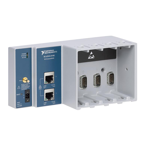
- Page 12 This chapter provides a cDAQ chassis overview and lists information about mounting the chassis and installing C Series modules. The National Instruments four-slot CompactDAQ cDAQ-9185 and eight-slot CompactDAQ cDAQ-9189 Ethernet chassis are designed for use with C Series modules. The cDAQ chassis are capable of measuring a broad range of analog and digital I/O signals and sensors.
-
Page 13: Getting Started With The Cdaq Chassis
SYNC Logo Chassis Grounding Screw Safety Guidelines Do not operate the NI cDAQ-9185/9189 in a manner not specified in this Caution user manual. Product misuse can result in a hazard. You can compromise the safety protection built into the product if the product is damaged in any way. If the product is damaged, return it to National Instruments for repair. -
Page 14: Special Guidelines For Marine Applications
Furthermore, any modifications to the product not expressly approved by National Instruments could void your authority to operate it under your local regulatory rules. -
Page 15: Hardware Symbol Definitions
NI recommends the use of system health monitoring and a user watchdog to ensure potential problems are detected and resolved as soon as possible. The cDAQ-9185/9189 has hardware and software features your application can use to monitor system health and respond to events such as hardware faults, software failure, system crash, or any loss of communication. - Page 16 When operating the cDAQ chassis in temperatures below 0 °C, you must use the PS-15 power supply or another power supply rated for below 0 °C. © National Instruments | 1-5 Artisan Technology Group - Quality Instrumentation ... Guaranteed | (888) 88-SOURCE | www.artisantg.com...
- Page 17 The NI-DAQmx software is included on the disk shipped with your kit and is available for download at . The documentation for NI-DAQmx is available after ni.com/drivers installation from Start»All Programs»National Instruments»NI-DAQmx. Other NI documentation is available from ni.com/manuals (Optional) Mount the cDAQ chassis to a panel, wall, or DIN rail, or attach the desktop...
- Page 18 Note the power connector with an external power supply rated for hazardous locations. The power supply included in the cDAQ-9185/9189 kit is intended only for desktop use. For all other applications use the included 2-position power connector plug and a power supply rated for your application power requirements. Visit to find ni.com...
- Page 19 Chapter 1 Getting Started with the cDAQ Chassis • If the chassis is on your local subnet, the chassis automatically appears in the list of available devices. Right-click the cDAQ chassis and select Add Device. If the chassis is not on your local subnet, right-click Network Devices and select Find •...
-
Page 20: Wiring External Power To The Cdaq Chassis
Some suggested NI power supplies are listed in Table 1-7. The cDAQ chassis filters and regulates the supplied power and provides © National Instruments | 1-9 Artisan Technology Group - Quality Instrumentation ... Guaranteed | (888) 88-SOURCE | www.artisantg.com... - Page 21 Chapter 1 Getting Started with the cDAQ Chassis power to all of the modules. The green POWER LED on the front panel identifies when the power input is in use. Complete the following steps to connect a power source to the cDAQ chassis. Make sure the power source is turned off.
-
Page 22: Connecting To A Real-Time Controller
User Manual Connecting to a Real-Time Controller You can use the cDAQ-9185/9189 chassis as expansion I/O from certain NI Linux Real-Time controllers. Discover and configure the NI Linux Real-Time controller in NI MAX, then discover and configure the cDAQ-9185/9189 chassis. - Page 23 Getting Started with the cDAQ Chassis Table 1-2. cDAQ Chassis NI-DAQmx Software Support cDAQ Chassis Earliest NI-DAQmx Version Support cDAQ-9185 NI-DAQmx 17.1 cDAQ-9189 NI-DAQmx 17.1 Set up your real-time controller hardware and install software to it as instructed in the getting started or quick start document for the real-time controller.
- Page 24 After the chassis is reserved by the real-time controller, the modules in the chassis are visible in the MAX configuration tree. Figure 1-9. Reserved cDAQ Chassis View in MAX © National Instruments | 1-13 Artisan Technology Group - Quality Instrumentation ... Guaranteed | (888) 88-SOURCE | www.artisantg.com...
-
Page 25: Troubleshooting Chassis Connectivity
Chapter 1 Getting Started with the cDAQ Chassis 12. Self-test your chassis in MAX by expanding the real-time controller»Devices and Interfaces»Network Devices, right-clicking NI cDAQ-<model number>, and selecting Self-Test. Self-test performs a brief test to determine successful chassis installation. When the self-test finishes, a message indicates successful verification or if an error occurred. -
Page 26: Reserving The Chassis In Max
C Series module accuracy. Observe the following guidelines to mount the cDAQ chassis in the reference mounting configuration. © National Instruments | 1-15 Artisan Technology Group - Quality Instrumentation ... Guaranteed | (888) 88-SOURCE | www.artisantg.com... - Page 27 Chapter 1 Getting Started with the cDAQ Chassis Figure 1-11. cDAQ Chassis Reference Mounting Configuration (cDAQ-9189 Shown) I N S T I O - 9 1 a c tD Horizontal mounting orientation. Mounting substrate options: • Mount the cDAQ chassis directly to a metallic surface that is at least 1.6 mm (0.062 in.) thick and extends a minimum of 101.6 mm (4 in.) beyond all edges of the device.
-
Page 28: Mounting Requirements
The different connector types on C Series modules require different cabling clearances. For a complete list of cabling clearances for C Series modules, visit ni.com/info and enter the Info Code crioconn © National Instruments | 1-17 Artisan Technology Group - Quality Instrumentation ... Guaranteed | (888) 88-SOURCE | www.artisantg.com... -
Page 29: Dimensions
(1.50 in.) (2.50 in.) (2.50 in.) Measure the ambient temperature here. Dimensions The following figures show the front and side dimensions of the cDAQ-9185 and cDAQ-9189. For detailed dimensional drawings and 3D models, visit and search for ni.com/dimensions cDAQ-9185 cDAQ-9189 1-18 | ni.com... - Page 30 User Manual Figure 1-15. cDAQ-9185 Dimensions 30.6 mm (1.20 in.) 47.2 mm (1.86 in.) POWER POWER STATUS STATUS NI cDAQ-9185 ACTIVE ACTIVE NI CompactDAQ 47.0 mm (1.85 in.) 88.1 mm (3.47 in.) PFI 0 PFI 0 DO NOT SEPARATE...
- Page 31 Chapter 1 Getting Started with the cDAQ Chassis Figure 1-16. cDAQ-9189 Dimensions 141.7 mm (5.58 in.) 47.2 mm 30.8 mm (1.86 in.) (1.21 in.) POWER POWER STATUS STATUS NI cDAQ-9189 ACTIVE ACTIVE 47.0 mm NI CompactDAQ (1.85 in.) 88.1 mm (3.47 in.) PFI 0 PFI 0...
-
Page 32: Mounting The Cdaq Chassis Directly On A Flat Surface
Fasten the cDAQ chassis to the surface using the M4 screws appropriate for the surface. Tighten the screws to a maximum torque of 1.3 N · m (11.5 lb · in.). © National Instruments | 1-21 Artisan Technology Group - Quality Instrumentation ... Guaranteed | (888) 88-SOURCE | www.artisantg.com... -
Page 33: Mounting The Cdaq Chassis On A Panel
1000 Mounting the cDAQ Chassis on a Panel You can use the NI 9904 panel mounting kit to mount the cDAQ-9185 on a panel. You can use the NI 9905 panel mounting kit to mount the cDAQ-9189 on a panel. - Page 34 Fasten the panel mounting plate to the surface using the screwdriver and screws that are appropriate for the surface. The maximum screw size is M5 or number 10. The following figures show the panel mounting dimensions for the cDAQ-9185 and cDAQ-9189.
-
Page 35: Alternate Mounting Configurations
You can use the NI DIN rail mounting kit to mount the cDAQ chassis on a standard 35-mm DIN rail. What to use: • cDAQ chassis • Screwdriver, Phillips #2 • NI 9912 DIN rail mounting kit, 779019-01 (cDAQ-9185) – DIN rail clip – M4x25 screws (x2) • NI 9915 DIN rail mounting kit, 779018-01 (cDAQ-9189) –... - Page 36 Press down firmly to compress the spring until the clip locks in place on the DIN rail. Ensure that no C Series modules are in the cDAQ chassis before removing Caution it from the DIN rail. © National Instruments | 1-25 Artisan Technology Group - Quality Instrumentation ... Guaranteed | (888) 88-SOURCE | www.artisantg.com...
-
Page 37: Mounting The Chassis On A Rack
Chapter 1 Getting Started with the cDAQ Chassis Mounting the Chassis on a Rack NI offers the following rack-mount kits that you can use to mount the cDAQ chassis and other DIN rail-mountable equipment on a standard 482.6 mm (19 in.) rack. •... - Page 38 Use the screwdriver and the two M3x20 screws to attach the adapter bracket to the chassis. Align one of the end brackets with the mounting hole at one of the ends of the chassis. © National Instruments | 1-27 Artisan Technology Group - Quality Instrumentation ... Guaranteed | (888) 88-SOURCE | www.artisantg.com...
-
Page 39: Cdaq Chassis Features
Chapter 1 Getting Started with the cDAQ Chassis Use a #2 Phillips screwdriver to tighten the captive screw on the end bracket. Repeat steps 2 and 3 to attach the other end bracket to the other end of the chassis. The following figures show the desktop mounting kit dimensions. -
Page 40: Ethernet Ports
A DAQ task is not running on the chassis Ethernet Ports The cDAQ-9185/9189 chassis has two tri-speed RJ-45 Ethernet ports—Ethernet Port 1 and Ethernet Port 2—as shown in Figure 1-1 or 1-2. You can use a shielded straight-through Category 5 Ethernet or an Ethernet crossover cable with either of the Ethernet ports to network your chassis to a computer host, NI Linux Real-Time controller, cDAQ chassis, or any network connection on the same subnet. -
Page 41: Ethernet Cabling
Chapter 1 Getting Started with the cDAQ Chassis Ethernet Cabling Table 1-5 shows the shielded Ethernet cable wiring connections for both straight-through and crossover cables. Table 1-5. Ethernet Cable Wiring Connections Connector 2 Connector 1 Straight-Through Crossover white/orange white/orange white/green orange orange green... -
Page 42: Reset Button
Note the power connector with an external power supply rated for hazardous locations. The power supply included in the cDAQ-9185/9189 kit is intended only for desktop use. For all other applications use the included 2-position power connector plug and a power supply rated for your application power requirements. Visit to find ni.com... -
Page 43: Chassis Grounding Screw
Time triggers and timestamps can be specified in Host Time or I/O Device Time, depending on the needs of your application. I/O Device Time—The time the cDAQ-9185/9189 uses internally. This time is determined • by the network configuration and is shared by all 802.1AS network-synchronized devices on your subnet. -
Page 44: Watchdog Timer
After the watchdog timer task starts, DAQmx tasks can be started and stopped and other operations can be performed. © National Instruments | 1-33 Artisan Technology Group - Quality Instrumentation ... Guaranteed | (888) 88-SOURCE | www.artisantg.com... -
Page 45: Firmware
Table 1-7 contains information about cables and accessories available for the cDAQ chassis. For a complete list of cDAQ chassis accessories and ordering information, refer to the pricing section of the NI cDAQ-9185/9189 product page at ni.com Table 1-7. Cables and Accessories... -
Page 46: Using The Cdaq Chassis
PFI 0 C Series Module National Instruments C Series modules provide built-in signal conditioning and connectivity, such as screw terminal, spring terminal, BNC, D-SUB, or RJ-50 connectors. A wide variety of I/O types are available, allowing you to customize the cDAQ system to meet your application needs. -
Page 47: Cdaq Module Interface
Chapter 1 Getting Started with the cDAQ Chassis cDAQ Module Interface The cDAQ module interface manages data transfers between the STC3 and the C Series modules. The interface also handles autodetection, signal routing, and synchronization. STC3 The STC3 features independent high-speed data streams; flexible AI, AO, and DIO sample timing, triggering, PFI signals for multi-device synchronization, flexible counter/timers with hardware gating, digital waveform acquisition and generation, and static DIO. -
Page 48: Ethernet Network Interface
Refer to Chapter 2, Networking, for information about cDAQ chassis daisy-chain topology and the internal Ethernet switch. © National Instruments | 1-37 Artisan Technology Group - Quality Instrumentation ... Guaranteed | (888) 88-SOURCE | www.artisantg.com... -
Page 49: Internal Ethernet Switch
Internal Ethernet Switch The cDAQ-9185/9189 chassis feature a full hardware-accelerated internal Ethernet switch for greater performance, wiring flexibility, and compatibility over standard Ethernet ports. The Ethernet switch exposes two Ethernet ports to the user. Either port can be used to connect the chassis to the network. -
Page 50: Ieee 802.1Q-2014 Rapid Spanning Tree Protocol (Rstp)
IEEE 802.1Q-2014 Rapid Spanning Tree Protocol (RSTP) It is possible to create loops in a network using the cDAQ-9185/9189. To prevent these loops from disrupting the network, the cDAQ chassis implements the IEEE 802.1Q-2014 Rapid Spanning Tree Protocol (RSTP). Using this protocol, each cDAQ chassis is able to find the shortest path for incoming packets to reach the rest of the network. -
Page 51: Topology Options
Host—Can be a PC or a real-time controller with the NI Linux Real-Time operating • system, such as the IC-317x, cRIO-9035 Sync, cRIO-9039 Sync, or cDAQ-9132/9133/9134/9135/9136/9137 for LabVIEW Real-Time Node—cDAQ-9185 or cDAQ-9189 chassis • For more information about designing Ethernet measurement systems, visit ni.com/info... -
Page 52: Ring Topology
Chapter 2 Networking Ring Topology In a ring topology, the host communicates with all nodes through the most effective path. You must use an external switch in a ring topology. You must configure the network properly with a recommended external switch before creating redundant links in the network. Refer to the External Switch Requirements section for information about what to look for in an external switch. -
Page 53: Other Topologies
Requires an external switch (external 802.1AS switch for network synchronization) • Covers the least distance Other Topologies For information about designing Ethernet measurement systems for synchronization, visit and enter ni.com/info cdaqenet © National Instruments | 2-5 Artisan Technology Group - Quality Instrumentation ... Guaranteed | (888) 88-SOURCE | www.artisantg.com... -
Page 54: External Switch Requirements
Networking External Switch Requirements To take advantage of the network synchronization and network redundancy features of the cDAQ-9185/9189, ensure that your network infrastructure meets certain requirements: IEEE 802.1AS-2011 time-based synchronization support—Automatically synchronizes • timebases and enables the use of time-based triggers, timestamping, and multi-device tasks between chassis across the network. -
Page 55: Analog Input
The cDAQ chassis features the following analog input timing signals: AI Sample Clock Signal* • AI Sample Clock Timebase Signal • AI Start Trigger Signal* • © National Instruments | 3-1 Artisan Technology Group - Quality Instrumentation ... Guaranteed | (888) 88-SOURCE | www.artisantg.com... -
Page 56: Ai Sample Clock Signal
Chapter 3 Analog Input AI Reference Trigger Signal* • AI Pause Trigger Signal* • PFI Filters Digital Signals with an * support digital filtering. Refer to the section of Chapter 5, Input/Output and PFI, for more information. AI Convert Clock Signal Behavior For Analog Input Modules Refer to the section for AI Convert Clock signals and the cDAQ chassis. -
Page 57: Ai Convert Clock Signal Behavior For Analog Input Modules
The sample rate of all modules in the task is an integer divisor of the frequency of the AI Sample Clock Timebase. © National Instruments | 3-3 Artisan Technology Group - Quality Instrumentation ... Guaranteed | (888) 88-SOURCE | www.artisantg.com... -
Page 58: Slow Sample Rate Modules
Chapter 3 Analog Input When one or more delta-sigma modules are in an analog input task, the delta-sigma modules also provide the signal used as the AI Sample Clock. This signal is used to cause A/D conversion for other modules in the system, just as the AI Sample Clock does when a delta-sigma module is not being used. -
Page 59: Ai Start Trigger Signal
Routing AI Start Trigger to an Output Terminal You can route the Start Trigger signal to any output PFI terminal. The output is an active high pulse. © National Instruments | 3-5 Artisan Technology Group - Quality Instrumentation ... Guaranteed | (888) 88-SOURCE | www.artisantg.com... -
Page 60: Ai Reference Trigger Signal
Chapter 3 Analog Input AI Reference Trigger Signal Use Reference Trigger to stop a measurement acquisition. To use a reference trigger, specify a buffer of finite size and a number of pretrigger samples (samples that occur before the reference trigger). The number of posttrigger samples (samples that occur after the reference trigger) desired is the buffer size minus the number of pretrigger samples. -
Page 61: Using An Analog Source
Depending on the C Series module capabilities, you may need two modules Note to utilize analog triggering. Pause triggers are only sensitive to the level of the source, not the edge. Note © National Instruments | 3-7 Artisan Technology Group - Quality Instrumentation ... Guaranteed | (888) 88-SOURCE | www.artisantg.com... -
Page 62: Analog Input Sync Pulse
Chapter 3 Analog Input Analog Input Sync Pulse You can use time as a trigger for sync pulses on delta-sigma C Series modules. To use a sync pulse with a time source, specify a specific time in NI-DAQmx. Refer to the Time Triggering topic in the NI-DAQmx Help for more information on accessing time-based features in the NI-DAQmx API. -
Page 63: Analog Output
Only one simultaneous update task can run at a time • A hardware-timed AO task and a simultaneous update AO task cannot run at the same time © National Instruments | 4-1 Artisan Technology Group - Quality Instrumentation ... Guaranteed | (888) 88-SOURCE | www.artisantg.com... -
Page 64: Hardware-Timed Generations
Chapter 4 Analog Output Hardware-Timed Generations With a hardware-timed generation, a digital hardware signal controls the rate of the generation. This signal can be generated internally on the chassis or provided externally. Hardware-timed generations have several advantages over software-timed acquisitions: •... -
Page 65: Analog Output Triggering Signals
PFI Filters Digital Signals with an * support digital filtering. Refer to the section of Chapter 5, Input/Output and PFI, for more information. © National Instruments | 4-3 Artisan Technology Group - Quality Instrumentation ... Guaranteed | (888) 88-SOURCE | www.artisantg.com... -
Page 66: Ao Sample Clock Signal
Chapter 4 Analog Output AO Sample Clock Signal The AO sample clock (ao/SampleClock) signals when all the analog output channels in the task update. AO Sample Clock can be generated from external or internal sources as shown in Figure 4-1. Figure 4-1. -
Page 67: Ao Start Trigger Signal
Routing AO Start Trigger Signal to an Output Terminal You can route AO Start Trigger to any output PFI terminal. The output is an active high pulse. © National Instruments | 4-5 Artisan Technology Group - Quality Instrumentation ... Guaranteed | (888) 88-SOURCE | www.artisantg.com... -
Page 68: Ao Pause Trigger Signal
Chapter 4 Analog Output AO Pause Trigger Signal Use the AO Pause Trigger signal (ao/PauseTrigger) to mask off samples in a DAQ sequence. When AO Pause Trigger is active, no samples occur, but AO Pause Trigger does not stop a sample that is in progress. -
Page 69: Using An Analog Source
DAC code changes. You can build a lowpass deglitching filter to remove some of these glitches, depending on the frequency and nature of the output signal. Go to for more ni.com/support information about minimizing glitches. © National Instruments | 4-7 Artisan Technology Group - Quality Instrumentation ... Guaranteed | (888) 88-SOURCE | www.artisantg.com... -
Page 70: Using The Watchdog Timer
Chapter 4 Analog Output Using the Watchdog Timer Watchdog Timer You can use the watchdog timer for analog output operations. Refer to the Getting Started with the cDAQ Chassis, for more information. section of Chapter 1, Getting Started with AO Applications in Software You can use the cDAQ chassis in the following analog output applications: •... -
Page 71: Digital Input/Output And Pfi
To determine the capability of digital modules supported by the cDAQ controller, refer to the C Series Support in NI-DAQmx document by going to and entering the Info ni.com/info Code rdcdaq © National Instruments | 5-1 Artisan Technology Group - Quality Instrumentation ... Guaranteed | (888) 88-SOURCE | www.artisantg.com... -
Page 72: Static Dio
Chapter 5 Digital Input/Output and PFI Static DIO Each of the DIO lines can be used as a static DI or DO line. You can use static DIO lines to monitor or control digital signals on some C Series modules. Each DIO line can be individually configured as a digital input (DI) or digital output (DO), if the C Series module being used allows such configuration. - Page 73 Use the following signals as the source: • AI Sample Clock • AO Sample Clock Counter n Internal Output • • Frequency Output • DI Change Detection Output © National Instruments | 5-3 Artisan Technology Group - Quality Instrumentation ... Guaranteed | (888) 88-SOURCE | www.artisantg.com...
- Page 74 Chapter 5 Digital Input/Output and PFI Several other internal signals can be routed to DI Sample Clock. Refer to the Device Routing in MAX topic in the NI-DAQmx Help or the LabVIEW Help for more information. Using an External Source You can route the following signals as DI Sample Clock: •...
- Page 75 Figure 5-2 shows the final buffer. Figure 5-2. Reference Trigger Final Buffer Reference Trigger Pretrigger Samples Posttrigger Samples Complete Buffer © National Instruments | 5-5 Artisan Technology Group - Quality Instrumentation ... Guaranteed | (888) 88-SOURCE | www.artisantg.com...
- Page 76 Chapter 5 Digital Input/Output and PFI Using a Digital Source To use DI Reference Trigger with a digital source, specify a source and a rising or falling edge. Either PFI or one of several internal signals on the cDAQ chassis can provide the source. Refer to the Device Routing in MAX topic in the NI-DAQmx Help or the LabVIEW Help for more information.
-
Page 77: Digital Input Filters
NI-DAQmx Help or the LabVIEW Help for more information. Tp is a nominal value; the accuracy of the chassis timebase and I/O distortion will affect this value. © National Instruments | 5-7 Artisan Technology Group - Quality Instrumentation ... Guaranteed | (888) 88-SOURCE | www.artisantg.com... -
Page 78: Change Detection Event
Chapter 5 Digital Input/Output and PFI Change Detection Event The Change Detection Event is the signal generated when a change on the rising or falling edge lines is detected by the change detection task. Routing Change Detection Event to an Output Terminal You can route ChangeDetectionEvent to any output PFI terminal. -
Page 79: Digital Output Data Generation Methods
FIFO to be written out. New data can be written to the host buffer at any time without disrupting the output. © National Instruments | 5-9 Artisan Technology Group - Quality Instrumentation ... Guaranteed | (888) 88-SOURCE | www.artisantg.com... -
Page 80: Digital Output Triggering Signals
Chapter 5 Digital Input/Output and PFI – With onboard regeneration, the entire buffer is downloaded to the FIFO and regenerated from there. After the data is downloaded, new data cannot be written to the FIFO. To use onboard regeneration, the entire buffer must fit within the FIFO size. The advantage of using onboard regeneration is that it does not require communication with the main host memory once the operation is started, which prevents problems that may occur due to excessive bus traffic or operating system latency. - Page 81 For more information, refer to the NI-DAQmx Help. © National Instruments | 5-11 Artisan Technology Group - Quality Instrumentation ... Guaranteed | (888) 88-SOURCE | www.artisantg.com...
- Page 82 Chapter 5 Digital Input/Output and PFI Using a Digital Source To use DO Start Trigger, specify a source and a rising or falling edge. The source can be one of the following signals: • A pulse initiated by host software •...
- Page 83 Depending on the C Series module capabilities, you may need two modules Note to utilize analog triggering. © National Instruments | 5-13 Artisan Technology Group - Quality Instrumentation ... Guaranteed | (888) 88-SOURCE | www.artisantg.com...
-
Page 84: Using The Watchdog Timer
Chapter 5 Digital Input/Output and PFI Using the Watchdog Timer Watchdog Timer You can use the watchdog timer for digital output operations. Refer to the Getting Started with the cDAQ Chassis, for more information. section of Chapter 1, Getting Started with DO Applications in Software You can use the cDAQ chassis in the following digital output applications: •... - Page 85 Figure 5-7. PFI Filter Example PFI Terminal Filtered input goes high when terminal is sampled high on Filter Clock five consecutive filter clocks. Filtered Input © National Instruments | 5-15 Artisan Technology Group - Quality Instrumentation ... Guaranteed | (888) 88-SOURCE | www.artisantg.com...
-
Page 86: Counters
The embedded counters cannot be programmed independent of the main counter; signals from the embedded counters are not routable. © National Instruments | 6-1 Artisan Technology Group - Quality Instrumentation ... Guaranteed | (888) 88-SOURCE | www.artisantg.com... -
Page 87: Counter Timing Engine
Chapter 6 Counters Counter Timing Engine Unlike analog input, analog output, digital input, and digital output, the cDAQ chassis counters do not have the ability to divide down a timebase to produce an internal counter sample clock. For sample clocked operations, an external signal must be provided to supply a clock source. The source can be any of the following signals: •... -
Page 88: Counter Triggering
The following sections list the various counter input applications available on the cDAQ chassis: Counting Edges • Pulse-Width Measurement • Pulse Measurement • Semi-Period Measurement • Frequency Measurement • © National Instruments | 6-3 Artisan Technology Group - Quality Instrumentation ... Guaranteed | (888) 88-SOURCE | www.artisantg.com... -
Page 89: Counting Edges
Chapter 6 Counters Period Measurement • Position Measurement • Counting Edges In edge counting applications, the counter counts edges on its Source after the counter is armed. You can configure the counter to count rising or falling edges on its Source input. You also can Controlling the Direction of control the direction of counting (up or down), as described in the Counting... -
Page 90: Buffered (Sample Clock) Edge Counting
Count up when the Counter 0 B input is high; count down when it is low Default Counter/Timer Routing For information about connecting counter signals, refer to the section. © National Instruments | 6-5 Artisan Technology Group - Quality Instrumentation ... Guaranteed | (888) 88-SOURCE | www.artisantg.com... -
Page 91: Pulse-Width Measurement
Chapter 6 Counters Pulse-Width Measurement In pulse-width measurements, the counter measures the width of a pulse on its Gate input signal. You can configure the counter to measure the width of high pulses or low pulses on the Gate signal. You can route an internal or external periodic clock signal (with a known period) to the Source input of the counter. -
Page 92: Implicit Buffered Pulse-Width Measurement
If a pulse does not occur between sample clocks, an overrun error occurs. Note Default Counter/Timer Routing For information about connecting counter signals, refer to the section. © National Instruments | 6-7 Artisan Technology Group - Quality Instrumentation ... Guaranteed | (888) 88-SOURCE | www.artisantg.com... -
Page 93: Pulse Measurement
Chapter 6 Counters Pulse Measurement In pulse measurements, the counter measures the high and low time of a pulse on its Gate input signal after the counter is armed. A pulse is defined in terms of its high and low time, high and low ticks or frequency and duty cycle. -
Page 94: Sample Clocked Buffered Pulse Measurement
If a pulse does not occur between sample clocks, an overrun error occurs. Note Default Counter/Timer Routing For information about connecting counter signals, refer to the section. © National Instruments | 6-9 Artisan Technology Group - Quality Instrumentation ... Guaranteed | (888) 88-SOURCE | www.artisantg.com... -
Page 95: Semi-Period Measurement
Chapter 6 Counters Semi-Period Measurement In semi-period measurements, the counter measures a semi-period on its Gate input signal after the counter is armed. A semi-period is the time between any two consecutive edges on the Gate input. You can route an internal or external periodic clock signal (with a known period) to the Source input of the counter. -
Page 96: Pulse Versus Semi-Period Measurements
(fk) to the Source of the counter. The known timebase can be an onboard timebase, such as 80 MHz Timebase, 20 MHz Timebase, or 100 kHz Timebase, or any other signal with a known rate. © National Instruments | 6-11 Artisan Technology Group - Quality Instrumentation ... Guaranteed | (888) 88-SOURCE | www.artisantg.com... -
Page 97: High Frequency With Two Counters
Chapter 6 Counters You can configure the counter to measure one period of the gate signal. The frequency of fx is the inverse of the period. Figure 6-12 illustrates this method. Figure 6-12. Low Frequency with One Counter Interval Measured Gate …... -
Page 98: Large Range Of Frequencies With Two Counters
Counter 0 is always paired with Counter 1. Counter 2 is always paired with Note Counter 3. © National Instruments | 6-13 Artisan Technology Group - Quality Instrumentation ... Guaranteed | (888) 88-SOURCE | www.artisantg.com... -
Page 99: Sample Clocked Buffered Frequency Measurement
Chapter 6 Counters You can route the signal to measure to the Source input of Counter 0, as shown in Figure 6-14. Assume this signal to measure has frequency fx. NI-DAQmx automatically configures Counter 0 to generate a single pulse that is the width of N periods of the source input signal. Figure 6-14. - Page 100 (T) is the time it takes to measure a single sample © National Instruments | 6-15 Artisan Technology Group - Quality Instrumentation ... Guaranteed | (888) 88-SOURCE | www.artisantg.com...
- Page 101 Chapter 6 Counters Divide down (N) is the integer to divide down measured frequency, only used in large range two counters is the sample clock rate, only used in sample clocked frequency measurements Here is how these variables apply to each method, summarized in Table 6-2. One counter—With one counter measurements, a known timebase is used for the source •...
-
Page 102: Which Method Is Best
.0002 time (mS) — — — 5,000 Max. 62.51 333 k 1,000 62.50 Frequency error (Hz) Max. Error % .00125 6.67 .00125 © National Instruments | 6-17 Artisan Technology Group - Quality Instrumentation ... Guaranteed | (888) 88-SOURCE | www.artisantg.com... - Page 103 Chapter 6 Counters Again, the measurement time for the one counter measurement is lowest but the accuracy is lower. Note that the accuracy and measurement time of the sample clocked and two counter large range are almost the same. The advantage of the sample clocked method is that even when the frequency to measure changes, the measurement time does not and error percentage varies little.
-
Page 104: Period Measurement
Refer to the following sections for more information about the cDAQ chassis position measurement options: Measurements Using Quadrature Encoders • Measurements Using Two Pulse Encoders • Buffered (Sample Clock) Position Measurement • © National Instruments | 6-19 Artisan Technology Group - Quality Instrumentation ... Guaranteed | (888) 88-SOURCE | www.artisantg.com... -
Page 105: Measurements Using Quadrature Encoders
Chapter 6 Counters Measurements Using Quadrature Encoders The counters can perform measurements of quadrature encoders that use X1, X2, or X4 encoding. A quadrature encoder can have up to three channels—channels A, B, and Z. X1 Encoding—When channel A leads channel B in a quadrature cycle, the counter •... -
Page 106: Measurements Using Two Pulse Encoders
The STC3 transfers the sampled values to host memory using a high-speed data stream. The count values returned are the cumulative counts © National Instruments | 6-21 Artisan Technology Group - Quality Instrumentation ... Guaranteed | (888) 88-SOURCE | www.artisantg.com... -
Page 107: Two-Signal Edge-Separation Measurement
Chapter 6 Counters since the counter armed event; that is, the sample clock does not reset the counter. You can route the counter sample clock to the Gate input of the counter. You can configure the counter to sample on the rising or falling edge of the sample clock. Figure 6-22 shows an example of a buffered X1 position measurement. -
Page 108: Single Two-Signal Edge-Separation Measurement
The counter counts the number of rising (or © National Instruments | 6-23 Artisan Technology Group - Quality Instrumentation ... Guaranteed | (888) 88-SOURCE | www.artisantg.com... -
Page 109: Counter Output Applications
Chapter 6 Counters falling) edges on the Source input occurring between an active edge of the Gate signal and an active edge of the Aux signal. The counter then stores the count in the FIFO on a sample clock edge. On the next active edge of the Gate signal, the counter begins another measurement. The STC3 transfers the sampled values to host memory using a high-speed data stream. -
Page 110: Single Pulse Generation
Figure 6-27 shows a generation of a pulse with a pulse delay of four and a pulse width of three (using the rising edge of Source). Figure 6-27. Single Pulse Generation with Start Trigger GATE (Start Trigger) SOURCE © National Instruments | 6-25 Artisan Technology Group - Quality Instrumentation ... Guaranteed | (888) 88-SOURCE | www.artisantg.com... -
Page 111: Pulse Train Generation
Chapter 6 Counters Pulse Train Generation Refer to the following sections for more information about the cDAQ chassis pulse train generation options: Finite Pulse Train Generation • Retriggerable Pulse or Pulse Train Generation • Continuous Pulse Train Generation • Buffered Pulse Train Generation •... -
Page 112: Continuous Pulse Train Generation
You can specify a delay from when the counter is armed to the beginning of the pulse train. The delay is measured in terms of a number of active edges of the Source input. © National Instruments | 6-27 Artisan Technology Group - Quality Instrumentation ... Guaranteed | (888) 88-SOURCE | www.artisantg.com... -
Page 113: Buffered Pulse Train Generation
Chapter 6 Counters You specify the high and low pulse widths of the output signal. The pulse widths are also measured in terms of a number of active edges of the Source input. You also can specify the active edge of the Source input (rising or falling). The counter can begin the pulse train generation as soon as the counter is armed, or in response to a hardware Start Trigger. -
Page 114: Finite Implicit Buffered Pulse Train Generation
When the last sample is generated, the pulse train continues to generate with Note these specifications until the task is stopped. © National Instruments | 6-29 Artisan Technology Group - Quality Instrumentation ... Guaranteed | (888) 88-SOURCE | www.artisantg.com... - Page 115 Chapter 6 Counters Table 6-7 and Figure 6-33 detail a finite sample clocked generation of three samples where the pulse specifications from the create channel are two ticks idle, two ticks active, and three ticks initial delay. Table 6-7. Finite Buffered Sample Clocked Pulse Train Generation Sample Idle Ticks Active Ticks...
-
Page 116: Continuous Buffered Sample Clocked Pulse Train Generation
Figure 6-35 shows the output waveform of the frequency generator when the divider is set to 5. Figure 6-35. Frequency Generator Output Waveform Frequency Output Timebase FREQ OUT (Divisor = 5) © National Instruments | 6-31 Artisan Technology Group - Quality Instrumentation ... Guaranteed | (888) 88-SOURCE | www.artisantg.com... -
Page 117: Frequency Division
Chapter 6 Counters Frequency Output can be routed out to any PFI terminal. All PFI terminals are set to high-impedance at startup. The FREQ OUT signal also can be routed to many internal timing signals. In software, program the frequency generator as you would program one of the counters for pulse train generation. -
Page 118: Counter Timing Signals
The selected edge of the Counter n Source signal increments and decrements the counter value depending on the application the counter is performing. Table 6-8 lists how this terminal is used in various applications. © National Instruments | 6-33 Artisan Technology Group - Quality Instrumentation ... Guaranteed | (888) 88-SOURCE | www.artisantg.com... -
Page 119: Routing A Signal To Counter N Source
Chapter 6 Counters Table 6-8. Counter Applications and Counter n Source Application Purpose of Source Terminal Pulse Generation Counter Timebase One Counter Time Measurements Counter Timebase Two Counter Time Measurements Input Terminal Non-Buffered Edge Counting Input Terminal Buffered Edge Counting Input Terminal Two-Edge Separation Counter Timebase... -
Page 120: Routing A Signal To Counter N Gate
Some of these options may not be available in some driver software. Refer to the Device Routing in MAX topic in the NI-DAQmx Help or the LabVIEW Help for more information about available routing options. © National Instruments | 6-35 Artisan Technology Group - Quality Instrumentation ... Guaranteed | (888) 88-SOURCE | www.artisantg.com... -
Page 121: Counter N A, Counter N B, And Counter N Z Signals
Chapter 6 Counters Counter n A, Counter n B, and Counter n Z Signals Counter n B can control the direction of counting in edge counting applications. Use the A, B, and Z inputs to each counter when measuring quadrature encoders or measuring two pulse encoders. -
Page 122: Counter N Sample Clock Signal
You can route Counter n Sample Clock out to any PFI terminal. The PFI circuitry inverts the polarity of Counter n Sample Clock before driving the PFI terminal. © National Instruments | 6-37 Artisan Technology Group - Quality Instrumentation ... Guaranteed | (888) 88-SOURCE | www.artisantg.com... -
Page 123: Counter N Internal Output And Counter N Tc Signals
Chapter 6 Counters Counter n Internal Output and Counter n TC Signals The Counter n Internal Output signal changes in response to Counter n TC. The two software-selectable output options are pulse output on TC and toggle output on TC. The output polarity is software-selectable for both options. -
Page 124: Prescaling
Depending on how you configure your chassis, the cDAQ chassis uses one of two synchronization methods: 80 MHz Source Mode • External or Internal Source Less than 20 MHz • © National Instruments | 6-39 Artisan Technology Group - Quality Instrumentation ... Guaranteed | (888) 88-SOURCE | www.artisantg.com... -
Page 125: 80 Mhz Source Mode
Chapter 6 Counters 80 MHz Source Mode In 80 MHz source mode, the chassis synchronizes signals on the rising edge of the source, and counts on the third rising edge of the source. Edges are pipelined so no counts are lost, as shown in Figure 6-38. -
Page 126: Digital Routing, Clock Generation, And Synchronization
Routes and generates the main clock signals for the cDAQ chassis. To determine the signal routing options for C Series module(s) installed in the cDAQ chassis, refer to the Device Routes tab in MAX. © National Instruments | 7-1 Artisan Technology Group - Quality Instrumentation ... Guaranteed | (888) 88-SOURCE | www.artisantg.com... -
Page 127: Clock Routing
Chapter 7 Digital Routing, Clock Generation, and Synchronization Clock Routing Figure 7-1 shows the clock routing circuitry of the cDAQ chassis. Figure 7-1. Clock Routing Circuitry Onboard Clock 100 MHz 80 MHz Timebase Generator Oscillator ÷ 20 MHz Timebase ÷ 100 kHz Timebase 13.1072 MHz Timebase 12.8 MHz Timebase... -
Page 128: Synchronization Across A Network
The cDAQ-9185/9189 chassis use the IEEE 802.1AS protocol over the network to synchronize. These cDAQ chassis can not synchronize over the network with devices that use protocols or IEEE 1588 profiles other than IEEE 802.1AS. -
Page 129: Appendix A Where To Go From Here
NI-DAQmx 17.1 or later. NI cDAQ Chassis Documentation The cDAQ-9185/9189 Quick Start packaged with your cDAQ chassis, describes how to install your NI-DAQmx for Windows software, how to install the cDAQ chassis and C Series module, and how to confirm that your device is operating properly. - Page 130 NI-DAQmx. Select Start»All Programs»National Instruments»NI-DAQmx»NI-DAQmx Readme. The NI-DAQmx Help contains API overviews, general information about measurement concepts, key NI-DAQmx concepts, and common applications that are applicable to all programming environments. Select Start»All Programs»National Instruments»Start» All Programs»National Instruments»NI-DAQmx»NI-DAQmx Help. LabVIEW Refer to for more information about LabVIEW.
- Page 131 Select Start»All Programs»National Instruments»NI-DAQmx»NI-DAQmx Help. The NI-DAQmx C Reference Help describes the NI-DAQmx Library functions, which you can use with National Instruments data acquisition devices to develop instrumentation, acquisition, and control applications. Select Start»All Programs»National Instruments»NI-DAQmx» Text-Based Code Support»NI-DAQmx C Reference Help.
- Page 132 Appendix A Where to Go from Here .NET Languages without NI Application Software With the Microsoft .NET Framework, you can use NI-DAQmx to create applications using Visual C# and Visual Basic .NET without Measurement Studio. Refer to the NI-DAQmx Readme for specific versions supported. Training Courses If you need more help getting started developing an application with NI products, NI offers training courses.
- Page 133 System Integration—If you have time constraints, limited in-house technical resources, or • other project challenges, National Instruments Alliance Partner members can help. To learn more, call your local NI office or visit ni.com/alliance © National Instruments | B-1...
- Page 134 Appendix B NI Services Training and Certification—The NI training and certification program is the most • effective way to increase application development proficiency and productivity. Visit for more information. ni.com/training – The Skills Guide assists you in identifying the proficiency requirements of your current application and gives you options for obtaining those skills consistent with your time and budget constraints and personal learning preferences.
- Page 135 6-24 Counter n Internal Output, 6-37 edge counting, 6-4 Counter n Source, 6-33 arm start trigger, 6-3 Counter n TC, 6-37 © National Instruments | I-1 Artisan Technology Group - Quality Instrumentation ... Guaranteed | (888) 88-SOURCE | www.artisantg.com...
- Page 136 Index Counter n Up_Down, 6-36 digital input signals FREQ OUT, 6-38 DI Pause Trigger, 5-6 Frequency Output, 6-38 DI Reference Trigger, 5-5 counters, 6-1 DI Sample Clock, 5-3 cascading, 6-38 DI Sample Clock Timebase, 5-3 edge counting, 6-4 DI Start Trigger, 5-4 generation, 6-24 digital output input applications, 6-3...
- Page 137 6-13 hardware-timed generations low frequency, 6-11 analog output, 4-2 minimizing glitches on the output signal, 4-7 digital output, 5-9 mounting, 1-15 © National Instruments | I-3 Artisan Technology Group - Quality Instrumentation ... Guaranteed | (888) 88-SOURCE | www.artisantg.com...
- Page 138 Index semi-period measurement, 6-10 implicit buffered, 6-10 .NET languages documentation, A-4 single, 6-10 NI-DAQmx, documentation, A-2 simple pulse generation, 6-24 single point edge counting, 6-4 on-demand edge counting, 6-4 pulse generation, 6-25 output signals, minimizing glitches, 4-7 retriggerable, 6-26 with start trigger, 6-25 pulse-width measurement, 6-6 pause trigger, 6-3 semi-period measurement, 6-10...
- Page 139 User Manual X1 encoding, 6-20 X2 encoding, 6-20 X4 encoding, 6-20 © National Instruments | I-5 Artisan Technology Group - Quality Instrumentation ... Guaranteed | (888) 88-SOURCE | www.artisantg.com...
- Page 140 Artisan Technology Group is your source for quality new and certified-used/pre-owned equipment SERVICE CENTER REPAIRS WE BUY USED EQUIPMENT • FAST SHIPPING AND DELIVERY Experienced engineers and technicians on staff Sell your excess, underutilized, and idle used equipment at our full-service, in-house repair center We also offer credit for buy-backs and trade-ins •...
Need help?
Do you have a question about the cDAQ-9185 and is the answer not in the manual?
Questions and answers