
Related Manuals for National Instruments cDAQ-9188XT


Summary of Contents for National Instruments cDAQ-9188XT
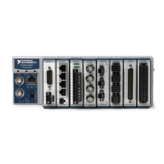
- Page 1 NI cDAQ -9188XT User Manual NI CompactDAQ Extended Temperature Rugged Eight-Slot Ethernet Chassis NI cDAQ-9188XT User Manual March 2016 373929C-01...
- Page 2 11500 North Mopac Expressway Austin, Texas 78759-3504 USA Tel: 512 683 0100 NI Services For further support information, refer to the appendix. To comment on NI ni.com/info feedback documentation, refer to the NI website at and enter the Info Code © 2013–2016 National Instruments. All rights reserved.
- Page 3 National Instruments Corporation. National Instruments respects the intellectual property of others, and we ask our users to do the same. NI software is protected by copyright and other intellectual property laws. Where NI software may be used to reproduce software or other materials belonging to others, you may use NI software only to reproduce materials that you may reproduce in accordance with the terms of any applicable license or other legal restriction.
- Page 4 ™ The ExpressCard word mark and logos are owned by PCMCIA and any use of such marks by National Instruments is under license. The mark LabWindows is used under a license from Microsoft Corporation. Windows is a registered trademark of Microsoft Corporation in the United States and other countries.
-
Page 5: Table Of Contents
Analog Input Analog Input Triggering Signals ..................2-1 Analog Input Timing Signals ................... 2-1 AI Sample Clock Signal ................... 2-2 Routing the Sample Clock to an Output Terminal ........... 2-2 AI Sample Clock Timebase Signal................2-2 © National Instruments | v... - Page 6 Contents AI Convert Clock Signal Behavior For Analog Input Modules ....... 2-2 Scanned Modules....................2-2 Simultaneous Sample-and-Hold Modules ............2-3 Sigma-Delta Modules ..................2-3 Slow Sample Rate Modules................2-4 AI Start Trigger Signal ..................... 2-4 Using a Digital Source ..................2-5 Using an Analog Source ...................
- Page 7 NI cDAQ-9188XT User Manual Chapter 4 Digital Input/Output and PFI Digital Input/Output ......................4-1 Serial DIO versus Parallel DIO Modules ..............4-1 Static DIO ......................... 4-2 Digital Input......................4-2 Digital Input Triggering Signals............... 4-2 Digital Input Timing Signals ................4-2 Digital Input Filters ..................
- Page 8 Contents Frequency Measurement...................5-10 Low Frequency with One Counter..............5-10 High Frequency with Two Counters..............5-11 Large Range of Frequencies with Two Counters ..........5-12 Sample Clocked Buffered Frequency Measurement ........5-13 Choosing a Method for Measuring Frequency ..........5-14 Which Method Is Best?..................5-16 Period Measurement ....................
- Page 9 NI cDAQ-9188XT User Manual Counter n A, Counter n B, and Counter n Z Signals ..........5-35 Routing Signals to A, B, and Z Counter Inputs..........5-35 Routing Counter n Z Signal to an Output Terminal ......... 5-36 Counter n Up_Down Signal ..................5-36 Counter n HW Arm Signal ..................
-
Page 10: Getting Started With The Cdaq Chassis
C Series modules. The National Instruments CompactDAQ Extended Temperature rugged eight-slot Ethernet chassis (cDAQ-9188XT) is designed for use with C Series modules. The cDAQ chassis is capable of measuring a broad range of analog and digital I/O signals and sensors. For module specifications, refer to the documentation included with your C Series module(s) or go to ni.com/manuals... -
Page 11: Electromagnetic Compatibility Guidelines
Getting Started with the cDAQ Chassis Because some C Series modules may have more stringent certification Note standards than the NI cDAQ-9188XT chassis, the combined system may be limited by individual component restrictions. Refer to the NI cDAQ-9188XT Specifications for more details. -
Page 12: Unpacking
At the end of the product life cycle, all products must be sent to EU Customers a WEEE recycling center. For more information about WEEE recycling centers, National Instruments WEEE initiatives, and compliance with WEEE Directive ni.com/environment/ 2002/96/EC on Waste and Electronic Equipment, visit... -
Page 13: Installing The Cdaq Chassis
(16 AWG) or larger wire. Use shorter wire for better EMC performance. You can either use a shielded straight through Category 5 Ethernet cable or an Ethernet crossover cable to connect the cDAQ chassis directly to your computer. NI-DAQmx 9.8 is the earliest support version for cDAQ-9188XT. 1-4 | ni.com... - Page 14 10. Wire your external power source as outlined in the section. The cDAQ chassis requires an external power supply that meets the specifications listed in the NI cDAQ-9188XT Specifications. The POWER and STATUS LEDs light. The POWER LED lights as long as power is being supplied to the cDAQ chassis.
- Page 15 Chapter 1 Getting Started with the cDAQ Chassis 11. To add the chassis, double-click the NI MAX icon on the desktop to open MAX. Expand Devices and Interfaces»Network Devices. • If the wired or wireless connection is on your local subnet, the chassis automatically appears in the list of available devices.
-
Page 16: Wiring Power To The Cdaq Chassis
The cDAQ chassis requires an external power source as described in the Power Requirements section of the NI cDAQ-9188XT Specifications. Some suggested NI power supplies are listed in Table 1-5. The cDAQ chassis filters and regulates the supplied power and provides power to all of the modules. - Page 17 Refer to the Power Requirements section of the NI cDAQ-9188XT Specifications for information about the power supply input range. Refer to the Safety Voltages section of the NI cDAQ-9188XT Specifications for information about the maximum voltage from terminal to chassis ground.
-
Page 18: Troubleshooting Chassis Connectivity
NI cDAQ-9188XT User Manual Troubleshooting Chassis Connectivity If your cDAQ chassis becomes disconnected from the network, try the following: • After moving the chassis to a new network, NI-DAQmx may lose connection to the chassis. In this case, click Reconnect to provide NI-DAQmx with the new hostname or IP address. -
Page 19: Mounting The Cdaq Chassis
Mounting the cDAQ Chassis You can use the cDAQ chassis on a desktop or mount it to a panel, wall, or DIN rail. For accessory ordering information, refer to the pricing section of the NI cDAQ-9188XT product ni.com page at... -
Page 20: Mounting The Cdaq Chassis On A Panel
You can then attach the panel mount accessory to a wall or panel with the two holes or the four keyholes with M4, M5, No. 8, or No. 10 panhead screws. National Instruments does not © National Instruments | 1-11... - Page 21 Getting Started with the cDAQ Chassis provide these screws with the chassis. Refer to the documentation included with the panel mount kit for more detailed dimensions. Figure 1-7. cDAQ-9188XT Panel Mount Dimensions and Installation 330.2 mm (13.00 in.) 88.1 mm (3.47 in.)
-
Page 22: Panel Mounting Without A Panel Mount Kit
You can mount the cDAQ chassis directly on a flat surface using the mounting holes. Refer to the NI cDAQ-9188XT Specifications for mounting dimensions for the cDAQ chassis. Drill appropriate holes in the mounting surface and align the chassis on the surface. Then, fasten the chassis to the surface using two M4 or No. - Page 23 Getting Started with the cDAQ Chassis Make sure the DIN rail kit is installed as shown in Figure 1-9. Figure 1-9. cDAQ-9188XT DIN Rail Installation Clip the chassis onto the DIN rail with the larger lip of the DIN rail clip positioned up, as shown in Figure 1-10.
-
Page 24: Ni Cdaq Chassis Features
A DAQ task is not running on the chassis Ethernet Port The cDAQ-9188XT chassis has one tri-speed RJ-45 Ethernet port, as shown in Figure 1-1. You can use a shielded straight through Category 5 Ethernet cable to connect one end to the RJ-45 Ethernet port on the chassis, and the other end directly to your computer or any network connection on the same subnet as your computer. -
Page 25: Ethernet Leds
Chapter 1 Getting Started with the cDAQ Chassis Ethernet LEDs The Ethernet port has two LEDs—10/100/1000 and LINK/ACT—described in Table 1-2. Table 1-2. Ethernet LED Indications Color LED State Chassis Status 10/100/1000 Yellow Connected at 1000 Mbps Green Connected at 100 Mbps —... -
Page 26: Ethernet Cabling
NI cDAQ-9188XT User Manual Ethernet Cabling Table 1-3 shows the shielded Ethernet cable wiring connections for both straight through and crossover cables. Table 1-3. Ethernet Cable Wiring Connections Connector 2 Connector 1 Normal Crossover white/orange white/orange white/green orange orange green... -
Page 27: Reset Button
Power Connector The cDAQ chassis ships with a 2-position power screw terminal connector plug for use with an external power source. Refer to the NI cDAQ-9188XT Specifications for information about the power connector on the cDAQ chassis. PFI BNC Connectors... -
Page 28: Cables And Accessories
Table 1-5 contains information about cables and accessories available for the cDAQ chassis. For a complete list of cDAQ chassis accessories and ordering information, refer to the pricing ni.com section of the NI cDAQ-9188XT product page at Table 1-5. Cables and Accessories Accessory... -
Page 29: Removing Modules From The Cdaq Chassis
PFI Terminals C Series Module National Instruments C Series modules provide built-in signal conditioning and screw terminal, spring terminal, BNC, D-SUB, or RJ-50 connectors. A wide variety of I/O types are available, allowing you to customize the cDAQ system to meet your application needs. -
Page 30: Parallel Versus Serial Dio Modules
NI cDAQ-9188XT User Manual Because the modules contain built-in signal conditioning for extended voltage ranges or industrial signal types, you can usually make your wiring connections directly from the C Series modules to your sensors/actuators. In most cases, the C Series modules provide isolation from channel-to-ground and channel-to-channel. - Page 31 Chapter 1 Getting Started with the cDAQ Chassis Triggering Modes—The cDAQ chassis supports different trigger modes, such as start • trigger, reference trigger, and pause trigger with analog, digital, or software sources. Refer to the following sections for more information: Analog Input Triggering Signals Analog Input –...
-
Page 32: Analog Input
The cDAQ chassis features the following analog input timing signals: AI Sample Clock Signal* • AI Sample Clock Timebase Signal • AI Start Trigger Signal* • AI Reference Trigger Signal* • AI Pause Trigger Signal* • © National Instruments | 2-1... -
Page 33: Ai Sample Clock Signal
Chapter 2 Analog Input PFI Filters Digital Signals with an * support digital filtering. Refer to the section of Chapter 4, Input/Output and PFI, for more information. AI Convert Clock Signal Behavior For Analog Input Modules Refer to the section for AI Convert Clock signals and the cDAQ chassis. -
Page 34: Simultaneous Sample-And-Hold Modules
NI cDAQ-9188XT User Manual Each Convert Clock signals the acquisition of a single channel from that module. The Convert Clock rate depends on the module being used, the number of channels used on that module, and the system Sample Clock rate. -
Page 35: Slow Sample Rate Modules
Chapter 2 Analog Input Slow Sample Rate Modules Some C Series analog input modules are specifically designed for measuring signals that vary slowly, such as temperature. Because of their slow rate, it is not appropriate for these modules to constrain the AI Sample Clock to operate at or slower than their maximum rate. When using such a module in the cDAQ chassis, the maximum Sample Clock rate can run faster than the maximum rate for the module. -
Page 36: Using A Digital Source
NI cDAQ-9188XT User Manual When you are using an internal sample clock, you can specify a default delay from the start trigger to the first sample. Using a Digital Source To use the Start Trigger signal with a digital source, specify a source and a rising or falling edge. -
Page 37: Using A Digital Source
Chapter 2 Analog Input When the reference trigger occurs, the cDAQ chassis continues to write samples to the buffer until the buffer contains the number of posttrigger samples desired. Figure 2-3 shows the final buffer. Figure 2-3. Reference Trigger Final Buffer Reference Trigger Pretrigger Samples Posttrigger Samples... -
Page 38: Using An Analog Source
NI cDAQ-9188XT User Manual Using an Analog Source Some C Series modules can generate a trigger based on an analog signal. In NI-DAQmx, this is called the Analog Comparison Event. When you use an analog trigger source, the internal sample clock pauses when the Analog Comparison Event signal is low and resumes when the signal goes high (or vice versa). -
Page 39: Analog Output
You can configure software-timed generations to simultaneously update • Only one simultaneous update task can run at a time • A hardware-timed AO task and a simultaneous update AO task cannot run at the same time © National Instruments | 3-1... -
Page 40: Hardware-Timed Generations
Chapter 3 Analog Output Hardware-Timed Generations With a hardware-timed generation, a digital hardware signal controls the rate of the generation. This signal can be generated internally on the chassis or provided externally. Hardware-timed generations have several advantages over software-timed acquisitions: •... -
Page 41: Analog Output Triggering Signals
NI cDAQ-9188XT User Manual Analog Output Triggering Signals Analog output supports two different triggering actions: AO Start Trigger and AO Pause Trigger. An analog or digital trigger can initiate these actions. Up to two C Series parallel digital input modules can be used in any chassis slot to supply a digital trigger. An analog trigger can be supplied by some C Series analog modules. -
Page 42: Ao Sample Clock Timebase Signal
Chapter 3 Analog Output AO Sample Clock Timebase Signal The AO Sample Clock Timebase (ao/SampleClockTimebase) signal is divided down to provide a source for AO Sample Clock. AO Sample Clock Timebase can be generated from external or internal sources, and is not available as an output from the chassis. AO Start Trigger Signal Use the AO Start Trigger (ao/StartTrigger) signal to initiate a waveform generation. -
Page 43: Using A Digital Source
NI cDAQ-9188XT User Manual When you generate analog output signals, the generation pauses as soon as the pause trigger is asserted. If the source of the sample clock is the onboard clock, the generation resumes as soon as the pause trigger is deasserted, as shown in Figure 3-2. -
Page 44: Minimizing Glitches On The Output Signal
Chapter 3 Analog Output Minimizing Glitches on the Output Signal When you use a DAC to generate a waveform, you may observe glitches on the output signal. These glitches are normal; when a DAC switches from one voltage to another, it produces glitches due to released charges. -
Page 45: Getting Started With Ao Applications In Software
NI cDAQ-9188XT User Manual Getting Started with AO Applications in Software You can use the cDAQ chassis in the following analog output applications: • Single-point (on-demand) generation • Finite generation • Continuous generation • Waveform generation For more information about programming analog output applications and triggers in software, refer the LabVIEW Help or to the NI-DAQmx Help. -
Page 46: Digital Input/Output And Pfi
You can only do hardware timing in one direction at a time on a serial bidirectional module. For more information about which C Series modules are compatible with the cDAQ chassis, go ni.com/info rdcdaq and enter the Info Code © National Instruments | 4-1... -
Page 47: Static Dio
Chapter 4 Digital Input/Output and PFI Static DIO Each of the DIO lines can be used as a static DI or DO line. You can use static DIO lines to monitor or control digital signals on some C Series modules. Each DIO line can be individually configured as a digital input (DI) or digital output (DO), if the C Series module being used allows such configuration. - Page 48 NI cDAQ-9188XT User Manual DI Sample Clock Signal Use the DI Sample Clock (di/SampleClock) signal to sample digital I/O on any slot using parallel digital modules, and store the result in the DI waveform acquisition FIFO. If the cDAQ chassis receives a DI Sample Clock signal when the FIFO is full, it reports an overflow error to the host software.
- Page 49 Chapter 4 Digital Input/Output and PFI Using an External Source You can route the following signals as DI Sample Clock: • Any PFI terminal • Analog Comparison Event (an analog trigger) You can sample data on the rising or falling edge of DI Sample Clock. Routing DI Sample Clock to an Output Terminal You can route DI Sample Clock to any output PFI terminal.
- Page 50 NI cDAQ-9188XT User Manual Routing DI Start Trigger to an Output Terminal You can route DI Start Trigger to any output PFI terminal. The output is an active high pulse. DI Reference Trigger Signal Use a reference trigger (di/ReferenceTrigger) signal to stop a measurement acquisition. To use a reference trigger, specify a buffer of finite size and a number of pretrigger samples (samples that occur before the reference trigger).
- Page 51 Chapter 4 Digital Input/Output and PFI Using an Analog Source Some C Series modules can generate a trigger based on an analog signal. In NI-DAQmx, this is called the Analog Comparison Event. When you use an analog trigger source, the acquisition stops on the first rising or falling edge of the Analog Comparison Event signal, depending on the trigger properties.
-
Page 52: Digital Input Filters
NI cDAQ-9188XT User Manual Digital Input Filters When performing a hardware timed task, you can enable a programmable debouncing filter on the digital input lines of a parallel DIO module. All lines on a module must share the same filter configuration. -
Page 53: Change Detection Event
Chapter 4 Digital Input/Output and PFI Change Detection Event The Change Detection Event is the signal generated when a change on the rising or falling edge lines is detected by the change detection task. Routing Change Detection Event to an Output Terminal You can route ChangeDetectionEvent to any output PFI terminal. -
Page 54: Digital Output Data Generation Methods
NI cDAQ-9188XT User Manual Digital Output Data Generation Methods When performing a digital output operation, you either can perform software-timed or hardware-timed generations. Hardware-timed generations must be buffered. Software-Timed Generations With a software-timed generation, software controls the rate at which data is generated. Software sends a separate command to the hardware to initiate each digital generation. -
Page 55: Digital Output Triggering Signals
Chapter 4 Digital Input/Output and PFI – With onboard regeneration, the entire buffer is downloaded to the FIFO and regenerated from there. After the data is downloaded, new data cannot be written to the FIFO. To use onboard regeneration, the entire buffer must fit within the FIFO size. The advantage of using onboard regeneration is that it does not require communication with the main host memory once the operation is started, which prevents problems that may occur due to excessive bus traffic or operating system latency. - Page 56 NI cDAQ-9188XT User Manual DO Sample Clock Signal The DO Sample Clock (do/SampleClock) signals when all the digital output channels in the task update. DO Sample Clock can be generated from external or internal sources as shown in Figure 4-4.
- Page 57 Chapter 4 Digital Input/Output and PFI You also can specify whether the waveform generation begins on the rising edge or falling edge of DO Start Trigger. Using an Analog Source Some C Series modules can generate a trigger based on an analog signal. In NI-DAQmx, this is called the Analog Comparison Event, depending on the trigger properties.
-
Page 58: Watchdog Timer
NI cDAQ-9188XT User Manual If you are using any signal other than the onboard clock as the source of the sample clock, the generation resumes as soon as the pause trigger is deasserted and another edge of the sample clock is received, as shown in Figure 4-6. -
Page 59: Getting Started With Do Applications In Software
Chapter 4 Digital Input/Output and PFI You can set the watchdog timer timeout period to specify the amount of time that must elapse before the watchdog timer expires. The counter on the watchdog timer is configurable up to - 1) × 25 ns (approximately 107 seconds) before it expires. When a watchdog timer expires, analog output, digital output, and counter output changes may be configured to transition to an expiration state. -
Page 60: Pfi
NI cDAQ-9188XT User Manual You can configure channels of a parallel digital module as Programmable Function Interface (PFI) terminals. The cDAQ chassis also provides two terminals for PFI. Up to two digital modules can be used to access PFI terminals in a single chassis. - Page 61 Chapter 4 Digital Input/Output and PFI On power up, the filters are disabled. Figure 4-7 shows an example of a low-to-high transition on an input that has a custom filter set to N = 5. Figure 4-7. PFI Filter Example PFI Terminal Filtered input goes high when terminal...
-
Page 62: Counters
(Embedded Ctrn) for use in what are traditionally two-counter measurements and generations. The embedded counters cannot be programmed independent of the main counter; signals from the embedded counters are not routable. © National Instruments | 5-1... -
Page 63: Counter Timing Engine
Chapter 5 Counters Counter Timing Engine Unlike analog input, analog output, digital input, and digital output, the cDAQ chassis counters do not have the ability to divide down a timebase to produce an internal counter sample clock. For sample clocked operations, an external signal must be provided to supply a clock source. The source can be any of the following signals: •... -
Page 64: Counter Input Applications
NI cDAQ-9188XT User Manual Counter Input Applications The following sections list the various counter input applications available on the cDAQ chassis: Counting Edges • Pulse-Width Measurement • Pulse Measurement • Semi-Period Measurement • Frequency Measurement • Period Measurement • Position Measurement •... -
Page 65: Buffered (Sample Clock) Edge Counting
Chapter 5 Counters You can route the pause trigger to the Gate input of the counter. You can configure the counter to pause counting when the pause trigger is high or when it is low. Figure 5-3 shows an example of on-demand edge counting with a pause trigger. -
Page 66: Pulse-Width Measurement
NI cDAQ-9188XT User Manual Pulse-Width Measurement In pulse-width measurements, the counter measures the width of a pulse on its Gate input signal. You can configure the counter to measure the width of high pulses or low pulses on the Gate signal. -
Page 67: Implicit Buffered Pulse-Width Measurement
Chapter 5 Counters Implicit Buffered Pulse-Width Measurement An implicit buffered pulse-width measurement is similar to single pulse-width measurement, but buffered pulse-width measurement takes measurements over multiple pulses. The counter counts the number of edges on the Source input while the Gate input remains active. On each trailing edge of the Gate signal, the counter stores the count in the counter FIFO. -
Page 68: Pulse Measurement
NI cDAQ-9188XT User Manual Pulse Measurement In pulse measurements, the counter measures the high and low time of a pulse on its Gate input signal after the counter is armed. A pulse is defined in terms of its high and low time, high and low ticks or frequency and duty cycle. -
Page 69: Sample Clocked Buffered Pulse Measurement
Chapter 5 Counters Figure 5-9 shows an example of an implicit buffered pulse measurement. Figure 5-9. Implicit Buffered Pulse Measurement Counter Armed Gate Source Buffer Sample Clocked Buffered Pulse Measurement A sample clocked buffered pulse measurement is similar to single pulse measurement, but a buffered pulse measurement takes measurements over multiple pulses correlated to a sample clock. -
Page 70: Semi-Period Measurement
NI cDAQ-9188XT User Manual Semi-Period Measurement In semi-period measurements, the counter measures a semi-period on its Gate input signal after the counter is armed. A semi-period is the time between any two consecutive edges on the Gate input. You can route an internal or external periodic clock signal (with a known period) to the Source input of the counter. -
Page 71: Pulse Versus Semi-Period Measurements
Chapter 5 Counters Default Counter/Timer Routing For information about connecting counter signals, refer to the section. Pulse versus Semi-Period Measurements In hardware, pulse measurement and semi-period are the same measurement. Both measure the high and low times of a pulse. The functional difference between the two measurements is how the data is returned. -
Page 72: High Frequency With Two Counters
NI cDAQ-9188XT User Manual You can configure the counter to measure one period of the gate signal. The frequency of fx is the inverse of the period. Figure 5-12 illustrates this method. Figure 5-12. Low Frequency with One Counter Interval Measured Gate …... -
Page 73: Large Range Of Frequencies With Two Counters
Chapter 5 Counters Figure 5-13 illustrates this method. Another option is to measure the width of a known period instead of a known pulse. Figure 5-13. High Frequency with Two Counters Width of Pulse (T ) Pulse Pulse Gate … Source Pulse-Width Width of... -
Page 74: Sample Clocked Buffered Frequency Measurement
NI cDAQ-9188XT User Manual You can route the signal to measure to the Source input of Counter 0, as shown in Figure 5-14. Assume this signal to measure has frequency fx. NI-DAQmx automatically configures Counter 0 to generate a single pulse that is the width of N periods of the source input signal. -
Page 75: Choosing A Method For Measuring Frequency
Chapter 5 Counters Figure 5-15. Sample Clocked Buffered Frequency Measurement (Averaging) Counter Armed Gate (fx) Source (fk) Sample Clock T1 T2 T1 T2 T1T2 Buffer 2 10 2 10 When CI.Freq.EnableAveraging is set to false, the frequency measurement returns the frequency of the pulse just before the sample clock. - Page 76 ------------------------ - fk fx N fk fx – – --- - 1 – Note: Accuracy equations do not take clock stability into account. Refer to the NI cDAQ-9188XT Specifications for information about clock stability. © National Instruments | 5-15...
-
Page 77: Which Method Is Best
Chapter 5 Counters Which Method Is Best? This depends on the frequency to be measured, the rate at which you want to monitor the frequency and the accuracy you desire. Take for example, measuring a 50 kHz signal. Assuming that the measurement times for the sample clocked (with averaging) and two counter frequency measurements are configured the same, Table 5-3 summarizes the results. - Page 78 NI cDAQ-9188XT User Manual Again the measurement time for the one counter measurement is lowest but the accuracy is lower. Note that the accuracy and measurement time of the sample clocked and two counter large range are almost the same. The advantage of the sample clocked method is that even when the frequency to measure changes, the measurement time does not and error percentage varies little.
-
Page 79: Period Measurement
Chapter 5 Counters Default Counter/Timer Routing For information about connecting counter signals, refer to the section. Period Measurement In period measurements, the counter measures a period on its Gate input signal after the counter is armed. You can configure the counter to measure the period between two rising edges or two falling edges of the Gate input signal. -
Page 80: Measurements Using Quadrature Encoders
NI cDAQ-9188XT User Manual Measurements Using Quadrature Encoders The counters can perform measurements of quadrature encoders that use X1, X2, or X4 encoding. A quadrature encoder can have up to three channels—channels A, B, and Z. X1 Encoding—When channel A leads channel B in a quadrature cycle, the counter •... -
Page 81: Measurements Using Two Pulse Encoders
Chapter 5 Counters Channel Z behavior—when it goes high and how long it stays high—differs with quadrature encoder designs. You must refer to the documentation for your quadrature encoder to obtain timing of channel Z with respect to channels A and B. You must then ensure that channel Z is high during at least a portion of the phase you specify for reload. -
Page 82: Two-Signal Edge-Separation Measurement
NI cDAQ-9188XT User Manual since the counter armed event; that is, the sample clock does not reset the counter. You can route the counter sample clock to the Gate input of the counter. You can configure the counter to sample on the rising or falling edge of the sample clock. -
Page 83: Single Two-Signal Edge-Separation Measurement
Chapter 5 Counters Single Two-Signal Edge-Separation Measurement With single two-signal edge-separation measurement, the counter counts the number of rising (or falling) edges on the Source input occurring between an active edge of the Gate signal and an active edge of the Aux signal. The counter then stores the count in the FIFO and ignores other edges on its inputs. -
Page 84: Counter Output Applications
NI cDAQ-9188XT User Manual falling) edges on the Source input occurring between an active edge of the Gate signal and an active edge of the Aux signal. The counter then stores the count in the FIFO on a sample clock edge. -
Page 85: Single Pulse Generation
Chapter 5 Counters Single Pulse Generation The counter can output a single pulse. The pulse appears on the Counter n Internal Output signal of the counter. You can specify a delay from when the counter is armed to the beginning of the pulse. The delay is measured in terms of a number of active edges of the Source input. -
Page 86: Pulse Train Generation
NI cDAQ-9188XT User Manual Pulse Train Generation Refer to the following sections for more information about the cDAQ chassis pulse train generation options: Finite Pulse Train Generation • Retriggerable Pulse or Pulse Train Generation • Continuous Pulse Train Generation •... -
Page 87: Continuous Pulse Train Generation
Chapter 5 Counters The counter ignores the Gate input while a pulse generation is in progress. After the pulse generation is finished, the counter waits for another Start Trigger signal to begin another pulse generation. For retriggered pulse generation, pause triggers are not allowed since the pause trigger also uses the gate input. -
Page 88: Buffered Pulse Train Generation
NI cDAQ-9188XT User Manual You specify the high and low pulse widths of the output signal. The pulse widths are also measured in terms of a number of active edges of the Source input. You also can specify the active edge of the Source input (rising or falling). -
Page 89: Finite Implicit Buffered Pulse Train Generation
Chapter 5 Counters Finite Implicit Buffered Pulse Train Generation This function generates a predetermined number of pulses with variable idle and active times. Each point you write generates a single pulse. The number of pairs of idle and active times (pulse specifications) you write determines the number of pulses generated. - Page 90 NI cDAQ-9188XT User Manual Table 5-7 and Figure 5-33 detail a finite sample clocked generation of three samples where the pulse specifications from the create channel are two ticks idle, two ticks active, and three ticks initial delay. Table 5-7. Finite Buffered Sample Clocked Pulse Train Generation...
-
Page 91: Continuous Buffered Sample Clocked Pulse Train Generation
Chapter 5 Counters Continuous Buffered Sample Clocked Pulse Train Generation This function generates a continuous train of pulses with variable idle and active times. Instead of generating a set number of data samples and stopping, a continuous generation continues until you stop the operation. -
Page 92: Frequency Division
NI cDAQ-9188XT User Manual Frequency Output can be routed out to any PFI terminal. All PFI terminals are set to high-impedance at startup. The FREQ OUT signal also can be routed to many internal timing signals. In software, program the frequency generator as you would program one of the counters for pulse train generation. -
Page 93: Pulse Generation For Ets
Chapter 5 Counters No other operations may be running on the cDAQ chassis while the watchdog Note timer task is being started; this includes all DAQmx tasks, calibration of modules, and routing and configuration of signals on the chassis. After the watchdog timer task starts, DAQmx tasks can be started and stopped and other operations can be performed. -
Page 94: Counter Timing Signals
NI cDAQ-9188XT User Manual Counter Timing Signals The cDAQ chassis features the following counter timing signals: Counter n Source Signal • Counter n Gate Signal • Counter n Aux Signal • Counter n A Signal • Counter n B Signal •... -
Page 95: Routing A Signal To Counter N Source
Chapter 5 Counters Table 5-8. Counter Applications and Counter n Source Application Purpose of Source Terminal Buffered Edge Counting Input Terminal Two-Edge Separation Counter Timebase Routing a Signal to Counter n Source Each counter has independent input selectors for the Counter n Source signal. Any of the following signals can be routed to the Counter n Source input: •... -
Page 96: Routing Counter N Gate To An Output Terminal
NI cDAQ-9188XT User Manual • Change Detection Event • Analog Comparison Event In addition, a counter’s Internal Output or Source can be routed to a different counter’s gate. Some of these options may not be available in some driver software. Refer to the Device Routing in MAX topic in the NI-DAQmx Help or the LabVIEW Help for more information about available routing options. -
Page 97: Routing Counter N Z Signal To An Output Terminal
Chapter 5 Counters Routing Counter n Z Signal to an Output Terminal You can route Counter n Z out to any PFI terminal. Counter n Up_Down Signal Counter n Up_Down is another name for the Counter n B signal. Counter n HW Arm Signal The Counter n HW Arm signal enables a counter to begin an input or output function. -
Page 98: Using An Internal Source
NI cDAQ-9188XT User Manual Using an Internal Source To use Counter n Sample Clock with an internal source, specify the signal source and the polarity of the signal. The source can be any of the following signals: • DI Sample Clock •... -
Page 99: Routing Frequency Output To A Terminal
Chapter 5 Counters Routing Frequency Output to a Terminal You can route Frequency Output to any PFI terminal. Default Counter/Timer Routing Counter/timer signals are available to parallel digital I/O C Series modules. To determine the signal routing options for modules installed in your system, refer to the Device Routes tab in MAX. -
Page 100: Other Counter Features
NI cDAQ-9188XT User Manual Other Counter Features The following sections list the other counter features available on the cDAQ chassis. Cascading Counters You can internally route the Counter n Internal Output and Counter n TC signals of each counter to the Gate inputs of the other counter. By cascading two counters together, you can effectively create a 64-bit counter. -
Page 101: 80 Mhz Source Mode
Chapter 5 Counters 80 MHz Source Mode In 80 MHz source mode, the chassis synchronizes signals on the rising edge of the source, and counts on the third rising edge of the source. Edges are pipelined so no counts are lost, as shown in Figure 5-38. -
Page 102: Digital Routing And Clock Generation
Routes tab in MAX. Clock Routing Figure 6-1 shows the clock routing circuitry of the cDAQ chassis. Figure 6-1. Clock Routing Circuitry 80 MHz Timebase Onboard 80 MHz ÷ 20 MHz Timebase Oscillator ÷ 100 kHz Timebase © National Instruments | 6-1... -
Page 103: 80 Mhz Timebase
Chapter 6 Digital Routing and Clock Generation 80 MHz Timebase You can use the 80 MHz Timebase as the Source input to the 32-bit general-purpose counter/timers. The 80 MHz Timebase can be generated from the onboard oscillator. 20 MHz Timebase The 20 MHz Timebase normally generates many of the AI and AO timing signals. -
Page 104: Where To Go From Here
NI-DAQmx 15.1 or later. NI cDAQ Chassis Documentation The NI cDAQ-9188XT Quick Start packaged with your cDAQ chassis, describes how to install your NI-DAQmx for Windows software, how to install the cDAQ chassis and C Series module, and how to confirm that your device is operating properly. - Page 105 NI-DAQmx. Select Start»All Programs»National Instruments»NI-DAQmx»NI-DAQmx Readme. The NI-DAQmx Help contains API overviews, general information about measurement concepts, key NI-DAQmx concepts, and common applications that are applicable to all programming environments. Select Start»All Programs»National Instruments»Start» All Programs»National Instruments»NI-DAQmx»NI-DAQmx Help. LabVIEW ni.com/gettingstarted Refer to for more information about LabVIEW.
- Page 106 Select Start»All Programs»National Instruments»NI-DAQmx» NI-DAQmx Help. The NI-DAQmx C Reference Help describes the NI-DAQmx Library functions, which you can use with National Instruments data acquisition devices to develop instrumentation, acquisition, and control applications. Select Start»All Programs»National Instruments»NI-DAQmx» Text-Based Code Support»NI-DAQmx C Reference Help.
- Page 107 Appendix A Where to Go from Here .NET Languages without NI Application Software With the Microsoft .NET Framework, you can use NI-DAQmx to create applications using Visual C# and Visual Basic .NET without Measurement Studio. Refer to the NI-DAQmx Readme for specific versions supported. Training Courses If you need more help getting started developing an application with NI products, NI offers ni.com/...
- Page 108 System Integration—If you have time constraints, limited in-house technical resources, or • other project challenges, National Instruments Alliance Partner members can help. To learn ni.com/alliance more, call your local NI office or visit © National Instruments | B-1...
- Page 109 Appendix B NI Services Training and Certification—The NI training and certification program is the most • effective way to increase application development proficiency and productivity. Visit ni.com/training for more information. – The Skills Guide assists you in identifying the proficiency requirements of your current application and gives you options for obtaining those skills consistent with ni.com/ your time and budget constraints and personal learning preferences.
- Page 110 Counter n A, 5-35 counter input, 5-3 Counter n Aux, 5-35 counter output, 5-23 Counter n B, 5-35 edge counting, 5-3 Counter n Gate, 5-34 arm start trigger, 5-38 Counter n HW Arm, 5-36 © National Instruments | I-1...
- Page 111 Index Counter n Internal Output, 5-37 digital input signals Counter n Source, 5-33 DI Pause Trigger, 4-6 Counter n TC, 5-37 DI Reference Trigger, 4-5 Counter n Up_Down, 5-36 DI Sample Clock, 4-3 FREQ OUT, 5-37 DI Sample Clock Timebase, 4-3 Frequency Output, 5-37 DI Start Trigger, 4-4 counters, 5-1...
- Page 112 NI cDAQ-9188XT User Manual digital output, 4-9 features, counter, 5-39 filters digital input (parallel DIO modules implicit buffered only), 4-7 pulse-width measurement, 5-6 PFI, 4-15 semi-period measurement, 5-9 FREQ OUT signal, 5-37 installation, 1-4 frequency internal source less than 40 MHz, 5-40...
- Page 113 Index mounting, 1-9 desktop use, 1-10 sample clock DIN rail, 1-13 edge counting, 5-4 panel/wall, 1-11 measurement, 5-20 semi-period measurement, 5-9 implicit buffered, 5-9 single, 5-9 .NET languages documentation, A-4 simple pulse generation, 5-23 NI-DAQmx, documentation, A-2 single point edge counting, 5-3 pulse generation, 5-24 on-demand edge counting, 5-3 retriggerable, 5-25...
- Page 114 NI cDAQ-9188XT User Manual unpacking, 1-3 using the cDAQ chassis, 1-20 watchdog timer, 3-6, 4-13, 5-31 X1 encoding, 5-19 X2 encoding, 5-19 X4 encoding, 5-19 © National Instruments | I-5...
Need help?
Do you have a question about the cDAQ-9188XT and is the answer not in the manual?
Questions and answers