Table of Contents
Advertisement
Quick Links
Advertisement
Table of Contents

Subscribe to Our Youtube Channel
Related Manuals for National Instruments cDAQ-9179


Summary of Contents for National Instruments cDAQ-9179
- Page 1 cDAQ-9179...
- Page 2 NI cDAQ -9179 User Manual 14-Slot USB 3.0 CompactDAQ Chassis Français Deutsch ni.com/manuals NI cDAQ-9179 User Manual August 2015 374937A-01...
- Page 3 11500 North Mopac Expressway Austin, Texas 78759-3504 USA Tel: 512 683 0100 For further support information, refer to the NI Services appendix. To comment on National Instruments documentation, refer to the National Instruments website at ni.com/info enter the Info Code feedback...
- Page 4 National Instruments Corporation. National Instruments respects the intellectual property of others, and we ask our users to do the same. NI software is protected by copyright and other intellectual property laws. Where NI software may be used to reproduce software or other materials belonging to others, you may use NI software only to reproduce materials that you may reproduce in accordance with the terms of any applicable license or other legal restriction.
- Page 5 ™ The ExpressCard word mark and logos are owned by PCMCIA and any use of such marks by National Instruments is under license. The mark LabWindows is used under a license from Microsoft Corporation. Windows is a registered trademark of Microsoft Corporation in the United States and other countries.
-
Page 6: Table Of Contents
Routing the Sample Clock to an Output Terminal ........... 2-2 AI Sample Clock Timebase Signal................2-2 AI Convert Clock Signal Behavior For Analog Input Modules....... 2-2 Scanned Modules....................2-2 Simultaneous Sample-and-Hold Modules ............2-3 Sigma-Delta Modules ..................2-3 Slow Sample Rate Modules................2-4 © National Instruments | v... - Page 7 Contents AI Start Trigger Signal ..................... 2-4 Using a Digital Source ..................2-5 Using an Analog Source ................... 2-5 Routing AI Start Trigger to an Output Terminal ..........2-5 AI Reference Trigger Signal..................2-5 Using a Digital Source ..................2-6 Using an Analog Source ...................
- Page 8 NI cDAQ-9179 User Manual Change Detection Event ................... 4-7 Routing Change Detection Event to an Output Terminal......... 4-7 Change Detection Acquisition................4-7 Digital Output ......................4-8 Digital Output Data Generation Methods............4-8 Digital Output Triggering Signals ..............4-10 Digital Output Timing Signals ................. 4-10 Getting Started with DO Applications in Software ..........
- Page 9 Contents Two-Signal Edge-Separation Measurement ............. 5-22 Single Two-Signal Edge-Separation Measurement .......... 5-23 Implicit Buffered Two-Signal Edge-Separation Measurement ......5-23 Sample Clocked Buffered Two-Signal Separation Measurement ....5-23 Counter Output Applications .................... 5-24 Simple Pulse Generation...................5-24 Single Pulse Generation..................5-25 Single Pulse Generation with Start Trigger ............5-25 Pulse Train Generation .....................
- Page 10 NI cDAQ-9179 User Manual Counter Triggering ......................5-38 Other Counter Features..................... 5-39 Cascading Counters ....................5-39 Prescaling........................5-39 Synchronization Modes .................... 5-39 80 MHz Source Mode..................5-40 External or Internal Source Less than 20 MHz ..........5-40 Chapter 6 Digital Routing and Clock Generation Digital Routing .........................
-
Page 11: Getting Started With The Cdaq Chassis
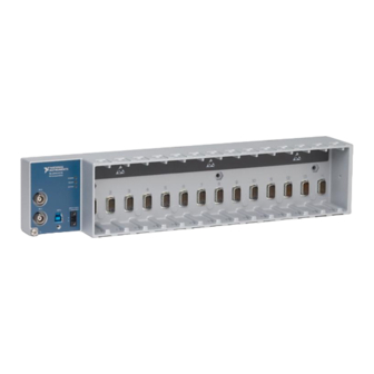
C Series modules. The 14-slot NI cDAQ-9179 USB chassis is designed for use with C Series modules. The cDAQ chassis is capable of measuring a broad range of analog and digital I/O signals using a SuperSpeed USB 3.0 interface. -
Page 12: Safety Guidelines For Hazardous Voltages
Getting Started with the cDAQ Chassis Note Because some C Series modules may have more stringent certification standards than the NI cDAQ-9179 chassis, the combined system may be limited by individual component restrictions. Refer to the NI cDAQ-9179 Specifications more details. -
Page 13: Hardware Symbol Definitions
At the end of the product life cycle, all products must be sent to a WEEE recycling center. For more information about WEEE recycling centers, National Instruments WEEE initiatives, and compliance with WEEE Directive 2002/96/EC on Waste and Electronic Equipment, visit ni.com/environment/... -
Page 14: Installing The Cdaq Chassis
Install NI-DAQmx. For more information, download the Read Me First: NI-DAQmx and DAQ Device Installation Guide. Note NI-DAQmx 15.1 is the earliest supported driver version for the cDAQ-9179. The NI-DAQmx software is included on the media shipped with your kit and is available for download at . - Page 15 NI cDAQ-9179 User Manual Figure 1-2. Ring Lug Attached to Ground Terminal - 9 1 a c t T IV 9 - 3 IN P Make sure that no signals are connected to the C Series module. Align the C Series module with the cDAQ chassis slot.
- Page 16 If an error occurs, refer to ni.com/support/daqmx 14. Run a Test Panel in MAX by expanding Devices and Interfaces»NI cDAQ-9179, right-clicking your C Series module, and selecting Test Panels to open a test panel for the selected module.
-
Page 17: Mounting The Cdaq Chassis
Mounting the cDAQ Chassis You can use the cDAQ chassis on a desktop or mount it to a panel, wall, DIN rail, or rack. For accessory ordering information, refer to the pricing section of the NI cDAQ-9179 product page ni.com The following sections contain mounting method information. -
Page 18: Using The Cdaq Chassis On A Desktop
Do not stack the cDAQ chassis. Installing the Desktop Mounting Kit The National Instruments Desktop Mounting Kit for 14-Slot CompactDAQ (part number 784302-01) is an accessory you can use to mount 14-slot chassis on a desktop. With this kit, you can tilt the cDAQ chassis for convenient access to the C Series module connectors. - Page 19 NI cDAQ-9179 User Manual Align one of the end brackets with the mounting hole at one of the ends of the chassis, as shown in Figure 1-5. Figure 1-5. Connecting the End Brackets to the Chassis -9 1 a c tD Use the screwdriver to tighten the captive screw on the end bracket.
-
Page 20: Mounting The Cdaq Chassis On A Panel
You can panel mount the cDAQ chassis with or without a panel mount kit. Installing the Panel Mount Kit The National Instruments panel mount kit for 14-slot CompactDAQ (part number 784303-01) is an accessory you can use to mount the 14-slot cDAQ chassis onto flat surfaces. The hardware in the kit consists of the panel mounting plate and three M4×21 screws. - Page 21 NI cDAQ-9179 User Manual Attach the panel mounting plate to a panel or wall using screws that are appropriate for the surface, as shown in Figure 1-8. Screws for mounting to a panel or wall are not included in the kit.
-
Page 22: Panel Mounting Without A Panel Mount Kit
Make sure that no C Series modules are in the chassis before removing it from the surface. Mounting the cDAQ Chassis on a DIN Rail Use the NI 9916 DIN rail kit (part number 780982-01) to mount the NI cDAQ-9179 chassis on a DIN rail. Each DIN rail kit contains one clip three ×... -
Page 23: Mounting The Cdaq Chassis On A Rack
NI cDAQ-9179 User Manual Figure 1-12. NI cDAQ-9179 DIN Rail Installation Clip the chassis onto the DIN rail with the larger lip of the DIN clip positioned up, as shown in Figure 1-13. Figure 1-13. DIN Rail Clip Parts Locator Diagram... -
Page 24: Cdaq Chassis Features
Chapter 1 Getting Started with the cDAQ Chassis cDAQ Chassis Features The cDAQ chassis features a chassis grounding screw, USB cable strain relief, LEDs, power connector, and two PFI BNC connectors. Refer to Figure 1-1 for locations of the cDAQ chassis features. -
Page 25: Usb 3.0 Port And Cable Strain Relief
USB cable by using the jackscrew on a locking USB cable to securely attach the cable to the chassis. Power Connector Refer to the NI cDAQ-9179 Specifications for information about the power connector on the cDAQ chassis. Cables and Accessories Table 1-2 contains information about cables and accessories available for the cDAQ chassis. -
Page 26: Using The Cdaq Chassis
I/O Module 8 C Series Module National Instruments C Series modules provide built-in signal conditioning and screw terminal, spring terminal, BNC, D-SUB, or RJ-50 connectors. A wide variety of I/O types are available, allowing you to customize the cDAQ system to meet your application needs. -
Page 27: Parallel Versus Serial Dio Modules
Digital Output Triggering Signals section of Chapter 4, Digital Input/Output and The cDAQ-9179 supports up to 12 data streams with a USB 3.0 SuperSpeed connection and up to eight data streams with a USB 2.0 Hi-Speed connection. © National Instruments | 1-17... - Page 28 PFI terminals provided on the cDAQ chassis. Refer to Chapter 5, Counters, for more information. The cDAQ-9179 supports up to 12 data streams with a USB 3.0 SuperSpeed connection and up to eight data streams with a USB 2.0 Hi-Speed connection.
-
Page 29: Analog Input
The cDAQ chassis features the following analog input timing signals: • AI Sample Clock Signal* • AI Sample Clock Timebase Signal • AI Start Trigger Signal* • AI Reference Trigger Signal* • AI Pause Trigger Signal* © National Instruments | 2-1... -
Page 30: Ai Sample Clock Signal
Chapter 2 Analog Input Signals with an * support digital filtering. Refer to the PFI Filters section of Chapter 4, Digital Input/Output and PFI, for more information. Refer to the AI Convert Clock Signal Behavior For Analog Input Modules section for AI Convert Clock signals and the cDAQ chassis. -
Page 31: Simultaneous Sample-And-Hold Modules
NI cDAQ-9179 User Manual Each Convert Clock signals the acquisition of a single channel from that module. The Convert Clock rate depends on the module being used, the number of channels used on that module, and the system Sample Clock rate. -
Page 32: Slow Sample Rate Modules
Chapter 2 Analog Input Slow Sample Rate Modules Some C Series analog input modules are specifically designed for measuring signals that vary slowly, such as temperature. Because of their slow rate, it is not appropriate for these modules to constrain the AI Sample Clock to operate at or slower than their maximum rate. When using such a module in the cDAQ chassis, the maximum Sample Clock rate can run faster than the maximum rate for the module. -
Page 33: Using A Digital Source
NI cDAQ-9179 User Manual When you are using an internal sample clock, you can specify a default delay from the start trigger to the first sample. Using a Digital Source To use the Start Trigger signal with a digital source, specify a source and a rising or falling edge. -
Page 34: Using A Digital Source
Chapter 2 Analog Input When the reference trigger occurs, the cDAQ chassis continues to write samples to the buffer until the buffer contains the number of posttrigger samples desired. Figure 2-3 shows the final buffer. Figure 2-3. Reference Trigger Final Buffer Reference Trigger Pretrigger Samples Posttrigger Samples... -
Page 35: Using An Analog Source
NI cDAQ-9179 User Manual Using an Analog Source Some C Series modules can generate a trigger based on an analog signal. In NI-DAQmx, this is called the Analog Comparison Event. When you use an analog trigger source, the internal sample clock pauses when the Analog Comparison Event signal is low and resumes when the signal goes high (or vice versa). -
Page 36: Analog Output
You can configure software-timed generations to simultaneously update • Only one simultaneous update task can run at a time • A hardware-timed AO task and a simultaneous update AO task cannot run at the same time © National Instruments | 3-1... -
Page 37: Hardware-Timed Generations
Chapter 3 Analog Output Hardware-Timed Generations With a hardware-timed generation, a digital hardware signal controls the rate of the generation. This signal can be generated internally on the chassis or provided externally. Hardware-timed generations have several advantages over software-timed acquisitions: •... -
Page 38: Analog Output Triggering Signals
NI cDAQ-9179 User Manual Analog Output Triggering Signals Analog output supports two different triggering actions: AO Start Trigger and AO Pause Trigger. An analog or digital trigger can initiate these actions. Up to two C Series parallel digital input modules can be used in any chassis slot to supply a digital trigger. An analog trigger can be supplied by some C Series analog modules. -
Page 39: Routing Ao Sample Clock To An Output Terminal
Chapter 3 Analog Output Routing AO Sample Clock to an Output Terminal You can route AO Sample Clock to any output PFI terminal. AO Sample Clock is active high by default. AO Sample Clock Timebase Signal The AO Sample Clock Timebase (ao/SampleClockTimebase) signal is divided down to provide a source for AO Sample Clock. -
Page 40: Ao Pause Trigger Signal
NI cDAQ-9179 User Manual AO Pause Trigger Signal Use the AO Pause Trigger signal (ao/PauseTrigger) to mask off samples in a DAQ sequence. When AO Pause Trigger is active, no samples occur, but AO Pause Trigger does not stop a sample that is in progress. -
Page 41: Minimizing Glitches On The Output Signal
Chapter 3 Analog Output Note Depending on the C Series module capabilities, you may need two modules to utilize analog triggering. Minimizing Glitches on the Output Signal When you use a DAC to generate a waveform, you may observe glitches on the output signal. These glitches are normal;... -
Page 42: Digital Input/Output And Pfi
You can only do hardware timing in one direction at a time on a serial bidirectional module. To determine the capability of digital modules supported by the cDAQ chassis, go to ni.com/ and enter the Info Code info rdcdaq © National Instruments | 4-1... -
Page 43: Static Dio
Chapter 4 Digital Input/Output and PFI Static DIO Each of the DIO lines can be used as a static DI or DO line. You can use static DIO lines to monitor or control digital signals on some C Series modules. Each DIO line can be individually configured as a digital input (DI) or digital output (DO), if the C Series module being used allows such configuration. - Page 44 NI cDAQ-9179 User Manual DI Sample Clock Signal Use the DI Sample Clock (di/SampleClock) signal to sample digital I/O on any slot using parallel digital modules, and store the result in the DI waveform acquisition FIFO. If the cDAQ chassis receives a DI Sample Clock signal when the FIFO is full, it reports an overflow error to the host software.
- Page 45 Chapter 4 Digital Input/Output and PFI Using an External Source You can route the following signals as DI Sample Clock: • Any PFI terminal • Analog Comparison Event (an analog trigger) You can sample data on the rising or falling edge of DI Sample Clock. Routing DI Sample Clock to an Output Terminal You can route DI Sample Clock to any output PFI terminal.
- Page 46 NI cDAQ-9179 User Manual Routing DI Start Trigger to an Output Terminal You can route DI Start Trigger to any output PFI terminal. The output is an active high pulse. DI Reference Trigger Signal Use a reference trigger (di/ReferenceTrigger) signal to stop a measurement acquisition. To use a reference trigger, specify a buffer of finite size and a number of pretrigger samples (samples that occur before the reference trigger).
-
Page 47: Digital Input Filters
Chapter 4 Digital Input/Output and PFI Using an Analog Source Some C Series modules can generate a trigger based on an analog signal. In NI-DAQmx, this is called the Analog Comparison Event. When you use an analog trigger source, the acquisition stops on the first rising or falling edge of the Analog Comparison Event signal, depending on the trigger properties. -
Page 48: Getting Started With Di Applications In Software
NI cDAQ-9179 User Manual In NI-DAQmx, the filter is programmed by setting the minimum pulse width, Tp , that will pass the filter, and is selectable in 25 ns increments. The appropriate Filter Clock is selected by the driver. Pulses of length less than 1/2 Tp will be rejected, and the filtering behavior of lengths between 1/2 Tp and 1 Tp are not defined because they depend on the phase of the Filter Clock relative to the input signal. -
Page 49: Digital Output
Chapter 4 Digital Input/Output and PFI Change detection acquisitions can be buffered or nonbuffered: • Nonbuffered Change Detection Acquisition—In a nonbuffered acquisition, data is transferred from the cDAQ chassis directly to a PC buffer. • Buffered Change Detection Acquisition—A buffer is a temporary storage in computer memory for acquired samples. - Page 50 NI cDAQ-9179 User Manual Hardware-Timed Generations With a hardware-timed generation, a digital hardware signal controls the rate of the generation. This signal can be generated internally on the chassis or provided externally. Hardware-timed generations have several advantages over software-timed acquisitions: •...
-
Page 51: Digital Output Triggering Signals
Chapter 4 Digital Input/Output and PFI Digital Output Triggering Signals Digital output supports two different triggering actions: DO Start Trigger and DO Pause Trigger. A digital or analog trigger can initiate these actions. Any PFI terminal can supply a digital trigger, and some C Series analog modules can supply an analog trigger. - Page 52 NI cDAQ-9179 User Manual DO Sample Clock Timebase Signal The DO Sample Clock Timebase (do/SampleClockTimebase) signal is divided down to provide a source for DO Sample Clock. DO Sample Clock Timebase can be generated from external or internal sources, and is not available as an output from the chassis.
- Page 53 Chapter 4 Digital Input/Output and PFI When you generate digital output signals, the generation pauses as soon as the pause trigger is asserted. If the source of the sample clock is the onboard clock, the generation resumes as soon as the pause trigger is deasserted, as shown in Figure 4-5. Figure 4-5.
-
Page 54: Getting Started With Do Applications In Software
NI cDAQ-9179 User Manual Getting Started with DO Applications in Software You can use the cDAQ chassis in the following digital output applications: • Single-point (on-demand) generation • Finite generation • Continuous generation For more information about programming digital output applications and triggers in software, refer to the LabVIEW Help or the NI-DAQmx Help. - Page 55 Chapter 4 Digital Input/Output and PFI Assume that an input terminal has been low for a long time. The input terminal then changes from low to high, but glitches several times. When the Filter Clock has sampled the signal high on N consecutive edges, the low-to-high transition is propagated to the rest of the circuit.
-
Page 56: Counters
(Embedded Ctrn) for use in what are traditionally two-counter measurements and generations. The embedded counters cannot be programmed independent of the main counter; signals from the embedded counters are not routable. © National Instruments | 5-1... -
Page 57: Counter Timing Engine
Chapter 5 Counters Counter Timing Engine Unlike analog input, analog output, digital input, and digital output, the cDAQ chassis counters do not have the ability to divide down a timebase to produce an internal counter sample clock. For sample clocked operations, an external signal must be provided to supply a clock source. The source can be any of the following signals: •... -
Page 58: Counter Input Applications
NI cDAQ-9179 User Manual Table 5-1. Counter Timing Measurements (Continued) Implicit Sample Clocked Measurement Timing Support Timing Support Buffered Position Buffered Two-Signal Edge Separation Counter Input Applications The following sections list the various counter input applications available on the cDAQ chassis: •... -
Page 59: Buffered (Sample Clock) Edge Counting
Chapter 5 Counters You also can use a pause trigger to pause (or gate) the counter. When the pause trigger is active, the counter ignores edges on its Source input. When the pause trigger is inactive, the counter counts edges normally. You can route the pause trigger to the Gate input of the counter. -
Page 60: Controlling The Direction Of Counting
NI cDAQ-9179 User Manual Controlling the Direction of Counting In edge counting applications, the counter can count up or down. You can configure the counter to do the following: • Always count up • Always count down • Count up when the Counter 0 B input is high; count down when it is low... -
Page 61: Single Pulse-Width Measurement
Chapter 5 Counters Single Pulse-Width Measurement With single pulse-width measurement, the counter counts the number of edges on the Source input while the Gate input remains active. When the Gate input goes inactive, the counter stores the count in the FIFO and ignores other edges on the Gate and Source inputs. Software then reads the stored count. -
Page 62: Sample Clocked Buffered Pulse-Width Measurement
NI cDAQ-9179 User Manual Sample Clocked Buffered Pulse-Width Measurement A sample clocked buffered pulse-width measurement is similar to single pulse-width measurement, but buffered pulse-width measurement takes measurements over multiple pulses correlated to a sample clock. The counter counts the number of edges on the Source input while the Gate input remains active. -
Page 63: Single Pulse Measurement
Chapter 5 Counters Single Pulse Measurement Single (on-demand) pulse measurement is equivalent to two single pulse-width measurements on the high (H) and low (L) ticks of a pulse, as shown in Figure 5-8. Figure 5-8. Single (On-Demand) Pulse Measurement Counter Armed Gate Source Latched... -
Page 64: Semi-Period Measurement
NI cDAQ-9179 User Manual Figure 5-10 shows an example of a sample clocked buffered pulse measurement. Figure 5-10. Sample Clocked Buffered Pulse Measurement Counter Armed Gate Source Sample Clock Buffer Note If a pulse does not occur between sample clocks, an overrun error occurs. -
Page 65: Implicit Buffered Semi-Period Measurement
Chapter 5 Counters Implicit Buffered Semi-Period Measurement In implicit buffered semi-period measurements, on each edge of the Gate signal, the counter stores the count in the FIFO. The STC3 transfers the sampled values to host memory using a high-speed data stream. The counter begins counting when it is armed. -
Page 66: Frequency Measurement
NI cDAQ-9179 User Manual Frequency Measurement You can use the counters to measure frequency in several different ways. Refer to the following sections for information about cDAQ chassis frequency measurement options: • Low Frequency with One Counter • High Frequency with Two Counters •... -
Page 67: Large Range Of Frequencies With Two Counters
Chapter 5 Counters In this method, you route a pulse of known duration (T) to the Gate of a counter. You can generate the pulse using a second counter. You also can generate the pulse externally and connect it to a PFI terminal. You only need to use one counter if you generate the pulse externally. Route the signal to measure (fx) to the Source of the counter. - Page 68 NI cDAQ-9179 User Manual You can route the signal to measure to the Source input of Counter 0, as shown in Figure 5-14. Assume this signal to measure has frequency fx. NI-DAQmx automatically configures Counter 0 to generate a single pulse that is the width of N periods of the source input signal.
-
Page 69: Sample Clocked Buffered Frequency Measurement
Chapter 5 Counters Sample Clocked Buffered Frequency Measurement Sample clocked buffered point frequency measurements can either be a single frequency measurement or an average between sample clocks. Use CI.Freq.EnableAveraging to set the behavior. For buffered frequency, the default is True. A sample clocked buffered frequency measurement with CI.Freq.EnableAveraging set to True uses the embedded counter and a sample clock to perform a frequency measurement. -
Page 70: Choosing A Method For Measuring Frequency
NI cDAQ-9179 User Manual With sample clocked frequency measurements, ensure that the frequency to measure is twice as fast as the sample clock to prevent a measurement overflow. Choosing a Method for Measuring Frequency The best method to measure frequency depends on several factors including the expected frequency of the signal to measure, the desired accuracy, how many counters are available, and how long the measurement can take. -
Page 71: Which Method Is Best
– --- - 1 – Note: Accuracy equations do not take clock stability into account. Refer to the NI cDAQ-9179 Specifications for information about clock stability. Which Method Is Best? This depends on the frequency to be measured, the rate at which you want to monitor the frequency and the accuracy you desire. - Page 72 NI cDAQ-9179 User Manual Table 5-3. 50 kHz Frequency Measurement Methods (Continued) Two Counter Sample High Variable Clocked One Counter Frequency Large Range Max. frequency .638 31.27 1,000 .625 error (Hz) Max. error % .00128 .0625 .00125 From this, you can see that while the measurement time for one counter is shorter, the accuracy is best in the sample clocked and two counter large range measurements.
-
Page 73: Period Measurement
Chapter 5 Counters must be at least twice the sample clock rate to ensure that a full period of the frequency to be measured occurs between sample clocks. • Low frequency measurements with one counter is a good method for many applications. However, the accuracy of the measurement decreases as the frequency increases. -
Page 74: Position Measurement
NI cDAQ-9179 User Manual You can route an internal or external periodic clock signal (with a known period) to the Source input of the counter. The counter counts the number of rising (or falling) edges occurring on the Source input between the two active edges of the Gate signal. -
Page 75: Channel Z Behavior
Chapter 5 Counters Figure 5-18. X2 Encoding Ch A Ch B Counter Value 5 • X4 Encoding—Similarly, the counter increments or decrements on each edge of channels A and B for X4 encoding. Whether the counter increments or decrements depends on which channel leads the other. -
Page 76: Measurements Using Two Pulse Encoders
NI cDAQ-9179 User Manual Figure 5-20. Channel Z Reload with X4 Decoding Ch A Ch B Ch Z Max Timebase Counter Value A = 0 B = 0 Z = 1 Measurements Using Two Pulse Encoders The counter supports two pulse encoders that have two channels—channels A and B. -
Page 77: Two-Signal Edge-Separation Measurement
Chapter 5 Counters Figure 5-22 shows an example of a buffered X1 position measurement. Figure 5-22. Buffered Position Measurement Counter Armed Sample Clock (Sample on Rising Edge) Ch A Ch B Count Buffer Two-Signal Edge-Separation Measurement Two-signal edge-separation measurement is similar to pulse-width measurement, except that there are two measurement signals—Aux and Gate. -
Page 78: Single Two-Signal Edge-Separation Measurement
NI cDAQ-9179 User Manual Single Two-Signal Edge-Separation Measurement With single two-signal edge-separation measurement, the counter counts the number of rising (or falling) edges on the Source input occurring between an active edge of the Gate signal and an active edge of the Aux signal. The counter then stores the count in the FIFO and ignores other edges on its inputs. -
Page 79: Counter Output Applications
Chapter 5 Counters falling) edges on the Source input occurring between an active edge of the Gate signal and an active edge of the Aux signal. The counter then stores the count in the FIFO on a sample clock edge. On the next active edge of the Gate signal, the counter begins another measurement. The STC3 transfers the sampled values to host memory using a high-speed data stream. -
Page 80: Single Pulse Generation
NI cDAQ-9179 User Manual Single Pulse Generation The counter can output a single pulse. The pulse appears on the Counter n Internal Output signal of the counter. You can specify a delay from when the counter is armed to the beginning of the pulse. The delay is measured in terms of a number of active edges of the Source input. -
Page 81: Pulse Train Generation
Chapter 5 Counters Pulse Train Generation Refer to the following sections for more information about the cDAQ chassis pulse train generation options: • Finite Pulse Train Generation • Retriggerable Pulse or Pulse Train Generation • Continuous Pulse Train Generation • Buffered Pulse Train Generation •... -
Page 82: Continuous Pulse Train Generation
NI cDAQ-9179 User Manual The counter ignores the Gate input while a pulse generation is in progress. After the pulse generation is finished, the counter waits for another Start Trigger signal to begin another pulse generation. For retriggered pulse generation, pause triggers are not allowed since the pause trigger also uses the gate input. -
Page 83: Buffered Pulse Train Generation
Chapter 5 Counters You specify the high and low pulse widths of the output signal. The pulse widths are also measured in terms of a number of active edges of the Source input. You also can specify the active edge of the Source input (rising or falling). The counter can begin the pulse train generation as soon as the counter is armed, or in response to a hardware Start Trigger. -
Page 84: Finite Implicit Buffered Pulse Train Generation
NI cDAQ-9179 User Manual Finite Implicit Buffered Pulse Train Generation This function generates a predetermined number of pulses with variable idle and active times. Each point you write generates a single pulse. The number of pairs of idle and active times (pulse specifications) you write determines the number of pulses generated. -
Page 85: Continuous Buffered Sample Clocked Pulse Train Generation
Chapter 5 Counters Table 5-7 and Figure 5-33 detail a finite sample clocked generation of three samples where the pulse specifications from the create channel are two ticks idle, two ticks active, and three ticks initial delay. Table 5-7. Finite Buffered Sample Clocked Pulse Train Generation Sample Idle Ticks Active Ticks... -
Page 86: Frequency Generation
NI cDAQ-9179 User Manual each sample clock. When a sample clock occurs, the current pulse finishes generation and the next pulse uses the next sample specifications. Frequency Generation You can generate a frequency by using a counter in pulse train generation mode or by using the... -
Page 87: Frequency Division
Chapter 5 Counters In software, program the frequency generator as you would program one of the counters for pulse train generation. For information about connecting counter signals, refer to the Default Counter/Timer Routing section. Frequency Division The counters can generate a signal with a frequency that is a fraction of an input signal. This function is equivalent to continuous pulse train generation. -
Page 88: Counter Timing Signals
NI cDAQ-9179 User Manual Counter Timing Signals The cDAQ chassis features the following counter timing signals: • Counter n Source Signal • Counter n Gate Signal • Counter n Aux Signal • Counter n A Signal • Counter n B Signal •... -
Page 89: Routing A Signal To Counter N Source
Chapter 5 Counters Routing a Signal to Counter n Source Each counter has independent input selectors for the Counter n Source signal. Any of the following signals can be routed to the Counter n Source input: • 80 MHz Timebase •... -
Page 90: Routing Counter N Gate To An Output Terminal
NI cDAQ-9179 User Manual Some of these options may not be available in some driver software. Refer to the Device Routing in MAX topic in the NI-DAQmx Help or the LabVIEW Help for more information about available routing options. Routing Counter n Gate to an Output Terminal You can route Counter n Gate out to any PFI terminal. -
Page 91: Counter N Up_Down Signal
Chapter 5 Counters Counter n Up_Down Signal Counter n Up_Down is another name for the Counter n B signal. Counter n HW Arm Signal The Counter n HW Arm signal enables a counter to begin an input or output function. To begin any counter input or output function, you must first enable, or arm, the counter. -
Page 92: Using An Internal Source
NI cDAQ-9179 User Manual Using an Internal Source To use Counter n Sample Clock with an internal source, specify the signal source and the polarity of the signal. The source can be any of the following signals: • DI Sample Clock •... -
Page 93: Routing Frequency Output To A Terminal
Chapter 5 Counters Routing Frequency Output to a Terminal You can route Frequency Output to any PFI terminal. Default Counter/Timer Routing Counter/timer signals are available to parallel digital I/O C Series modules. To determine the signal routing options for modules installed in your system, refer to the Device Routes tab in MAX. -
Page 94: Other Counter Features
NI cDAQ-9179 User Manual Other Counter Features The following sections list the other counter features available on the cDAQ chassis. Cascading Counters You can internally route the Counter n Internal Output and Counter n TC signals of each counter to the Gate inputs of the other counter. By cascading two counters together, you can effectively create a 64-bit counter. -
Page 95: 80 Mhz Source Mode
Chapter 5 Counters 80 MHz Source Mode In 80 MHz source mode, the chassis synchronizes signals on the rising edge of the source, and counts on the third rising edge of the source. Edges are pipelined so no counts are lost, as shown in Figure 5-38. -
Page 96: Digital Routing And Clock Generation
Figure 6-1. Clock Routing Circuitry 80 MHz Timebase Onboard 80 MHz 20 MHz Timebase Oscillator ÷ 100 kHz Timebase ÷ 80 MHz Timebase You can use the 80 MHz Timebase as the Source input to the 32-bit general-purpose counter/timers. © National Instruments | 6-1... -
Page 97: 20 Mhz Timebase
Chapter 6 Digital Routing and Clock Generation 20 MHz Timebase The 20 MHz Timebase normally generates many of the AI and AO timing signals. It can function as the Source input to the 32-bit general-purpose counter/timers. The 20 MHz Timebase is generated by dividing down the 80 MHz Timebase, as shown in Figure 6-1. -
Page 98: Appendix A Where To Go From Here
NI-DAQmx 9.8 or later. NI cDAQ Chassis Documentation The NI cDAQ-9179 Quick Start packaged with your cDAQ chassis, describes how to install your NI-DAQmx for Windows software, how to install the cDAQ chassis and C Series module, and how to confirm that your device is operating properly. - Page 99 Where to Go from Here NI-DAQmx The NI-DAQmx Readme lists which devices, ADEs, and NI application software are supported by this version of NI-DAQmx. Select Start»All Programs»National Instruments» NI-DAQmx»NI-DAQ Readme. The NI-DAQmx Help contains API overviews, general information about measurement concepts, key NI-DAQmx concepts, and common applications that are applicable to all programming environments.
- Page 100 Select Start»All Programs»National Instruments»NI-DAQmx»NI-DAQmx Help. The NI-DAQmx C Reference Help describes the NI-DAQmx Library functions, which you can use with National Instruments data acquisition devices to develop instrumentation, acquisition, and control applications. Select Start»All Programs»National Instruments»NI-DAQmx» Text-Based Code Support»NI-DAQmx C Reference Help.
- Page 101 Appendix A Where to Go from Here .NET Languages without NI Application Software With the Microsoft .NET Framework, you can use NI-DAQmx to create applications using Visual C# and Visual Basic .NET without Measurement Studio. Refer to the NI-DAQmx Readme for specific versions supported. Training Courses If you need more help getting started developing an application with NI products, NI offers training courses.
- Page 102 NI Services National Instruments provides global services and support as part of our commitment to your success. Take advantage of product services in addition to training and certification programs that meet your needs during each phase of the application life cycle; from planning and development through deployment and ongoing maintenance.
- Page 103 Appendix B NI Services • Training and Certification—The NI training and certification program is the most effective way to increase application development proficiency and productivity. Visit for more information. ni.com/training – The Skills Guide assists you in identifying the proficiency requirements of your current application and gives you options for obtaining those skills consistent with your time and budget constraints and personal learning preferences.
- Page 104 Counter n Aux, 5-35 applications Counter n B, 5-35 counter input, 5-3 Counter n Gate, 5-34 counter output, 5-24 Counter n HW Arm, 5-36 edge counting, 5-3 Counter n Internal Output, 5-37 arm start trigger, 5-38 © National Instruments | I-1...
- Page 105 Index Counter n Source, 5-33 digital input signals Counter n TC, 5-37 DI Pause Trigger, 4-6 Counter n Up_Down, 5-36 DI Reference Trigger, 4-5 FREQ OUT, 5-37 DI Sample Clock, 4-3 Frequency Output, 5-37 DI Sample Clock Timebase, 4-3 counters, 5-1 DI Start Trigger, 4-4 cascading, 5-39 digital output...
- Page 106 NI cDAQ-9179 User Manual features, 1-14 hardware-timed generations features, counter, 5-39 analog output, 3-2 filters digital output, 4-9 digital input (parallel DIO modules only), 4-6 PFI, 4-13 implicit buffered FREQ OUT signal, 5-37 pulse-width measurement, 5-6 frequency semi-period measurement, 5-10...
- Page 107 Index mounting desktop use, 1-8 reciprocal frequency measurement, 5-12 DIN rail, 1-12 related documentation, A-1 panel, 1-10 retriggerable single pulse generation, 5-26 routing clock, 6-1 digital, 6-1 .NET languages documentation, A-4 NI-DAQmx device documentation browser, A-1 documentation, A-2 safety guidelines, 1-1 for hazardous voltages, 1-2 sample clock edge counting, 5-4...
- Page 108 NI cDAQ-9179 User Manual technical support, A-4 unpacking, 1-3 timebase using the cDAQ chassis, 1-16 100 kHz, 6-2 20 MHz, 6-2 80 MHz, 6-1 X1 encoding, 5-19 training, A-4 X2 encoding, 5-19 TRIG (PFI) BNC connectors, 1-14 X4 encoding, 5-20...
Need help?
Do you have a question about the cDAQ-9179 and is the answer not in the manual?
Questions and answers