
Related Manuals for National Instruments NI cDAQ-9178


Summary of Contents for National Instruments NI cDAQ-9178
- Page 1 (217) 352-9330 | Click HERE Find the National Instruments cDAQ-9171 at our website:...
- Page 2 NI cDAQ -9171/9174/9178 User Manual NI CompactDAQ USB 2.0 Chassis NI cDAQ-9171/9174/9178 User Manual July 2016 372838E-01 Artisan Technology Group - Quality Instrumentation ... Guaranteed | (888) 88-SOURCE | www.artisantg.com...
- Page 3 For further support information, refer to the appendix. To comment on NI ni.com/info feedback documentation, refer to the NI website at and enter the Info Code © 2009–2016 National Instruments. All rights reserved. Artisan Technology Group - Quality Instrumentation ... Guaranteed | (888) 88-SOURCE | www.artisantg.com...
- Page 4 National Instruments Corporation. National Instruments respects the intellectual property of others, and we ask our users to do the same. NI software is protected by copyright and other intellectual property laws. Where NI software may be used to reproduce software or other materials belonging to others, you may use NI software only to reproduce materials that you may reproduce in accordance with the terms of any applicable license or other legal restriction.
- Page 5 The ExpressCard ™ word mark and logos are owned by PCMCIA and any use of such marks by National Instruments is under license. The mark LabWindows is used under a license from Microsoft Corporation. Windows is a registered trademark of Microsoft Corporation in the United States and other countries.
-
Page 6: Table Of Contents
AI Convert Clock Signal Behavior For Analog Input Modules....... 2-2 Scanned Modules....................2-3 Simultaneous Sample-and-Hold Modules ............2-3 Sigma-Delta Modules ..................2-3 Slow Sample Rate Modules................2-4 © National Instruments | v Artisan Technology Group - Quality Instrumentation ... Guaranteed | (888) 88-SOURCE | www.artisantg.com... - Page 7 Contents AI Start Trigger Signal ..................... 2-5 Using a Digital Source ..................2-5 Using an Analog Source ................... 2-5 Routing AI Start Trigger to an Output Terminal ..........2-5 AI Reference Trigger Signal..................2-5 Using a Digital Source ..................2-6 Using an Analog Source ...................
- Page 8 Measurements Using Quadrature Encoders ............. 5-18 Channel Z Behavior....................5-19 Measurements Using Two Pulse Encoders ............5-20 Buffered (Sample Clock) Position Measurement..........5-20 © National Instruments | vii Artisan Technology Group - Quality Instrumentation ... Guaranteed | (888) 88-SOURCE | www.artisantg.com...
- Page 9 Contents Two-Signal Edge-Separation Measurement ............. 5-21 Single Two-Signal Edge-Separation Measurement .......... 5-21 Implicit Buffered Two-Signal Edge-Separation Measurement ......5-22 Sample Clocked Buffered Two-Signal Separation Measurement ....5-22 Counter Output Applications .................... 5-23 Simple Pulse Generation...................5-23 Single Pulse Generation..................5-23 Single Pulse Generation with Start Trigger ............5-24 Pulse Train Generation .....................
- Page 10 20 MHz Timebase ....................6-2 100 kHz Timebase ....................6-2 Appendix A Where to Go from Here Appendix B NI Services Index © National Instruments | ix Artisan Technology Group - Quality Instrumentation ... Guaranteed | (888) 88-SOURCE | www.artisantg.com...
-
Page 11: Getting Started With The Cdaq Chassis
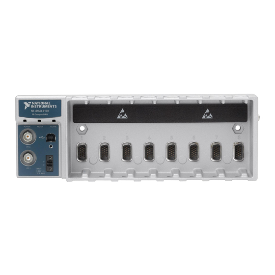
This chapter provides an NI CompactDAQ chassis overview and lists information about mounting the chassis and installing C Series modules. The one-slot NI cDAQ-9171, four-slot NI cDAQ-9174, and eight-slot NI cDAQ-9178 USB chassis are designed for use with C Series modules. The cDAQ chassis are capable of measuring a broad range of analog and digital I/O signals using a Hi-Speed USB 2.0 interface. - Page 12 15 W MAX POWER, READY, and ACTIVE LEDs Module Slots USB Connector with Strain Relief Chassis Grounding Screw Power Connector Figure 1-3 shows the cDAQ-9178 chassis. Figure 1-3. cDAQ-9178 Chassis NI cDAQ-9178 NI CompactDAQ POWER READY ACTIVE TRIG 0 INPUT TRIG 1...
-
Page 13: Safety Guidelines
To minimize the potential for the product to cause interference to radio and television reception or to experience unacceptable performance © National Instruments | 1-3 Artisan Technology Group - Quality Instrumentation ... Guaranteed | (888) 88-SOURCE | www.artisantg.com... -
Page 14: Hardware Symbol Definitions
At the end of the product life cycle, all products must be sent to EU Customers a WEEE recycling center. For more information about WEEE recycling centers, National Instruments WEEE initiatives, and compliance with WEEE Directive ni.com/environment/ 2002/96/EC on Waste and Electronic Equipment, visit... -
Page 15: Installing The Cdaq Chassis
Note ni.com/support available for download at . The documentation for NI-DAQmx is available after installation from Start»All Programs»National Instruments» NI-DAQ. Other NI documentation is available from ni.com/manuals © National Instruments | 1-5 Artisan Technology Group - Quality Instrumentation ... Guaranteed | (888) 88-SOURCE | www.artisantg.com... - Page 16 Chapter 1 Getting Started with the cDAQ Chassis Table 1-1 lists the earliest NI-DAQmx support version for each cDAQ chassis. Table 1-1. cDAQ Chassis NI-DAQmx Software Support cDAQ Chassis NI-DAQmx Version Support cDAQ-9171 NI-DAQmx 9.4 and later cDAQ-9174 NI-DAQmx 9.0.2 and later cDAQ-9178 NI-DAQmx 9.0.2 and later (Optional) Mount the cDAQ chassis to a panel, wall, or DIN rail as described in the...
-
Page 17: Mounting The Cdaq Chassis
DIN rail. For accessory ordering information, refer to the pricing ni.com section of your cDAQ chassis product page at © National Instruments | 1-7 Artisan Technology Group - Quality Instrumentation ... Guaranteed | (888) 88-SOURCE | www.artisantg.com... -
Page 18: Using The Cdaq Chassis On A Desktop
Chapter 1 Getting Started with the cDAQ Chassis Your installation must meet the following requirements: Caution • Allows 25.4 mm (1 in.) of clearance above and below the cDAQ chassis for air circulation. • Allows at least 50.8 mm (2 in.) of clearance in front of the modules for common connector cabling such as the 10-terminal detachable screw terminal connector and, as needed, up to 88.9 mm (3.5 in.) of clearance in front of the modules for other types of cabling. -
Page 19: Mounting The Cdaq Chassis On A Panel
M4, M5, No. 8, or No.10 panhead screws. Refer to the documentation included with the panel mount kit for more detailed dimensions. © National Instruments | 1-9 Artisan Technology Group - Quality Instrumentation ... Guaranteed | (888) 88-SOURCE | www.artisantg.com... - Page 20 Chapter 1 Getting Started with the cDAQ Chassis Figure 1-6. cDAQ-9174/9178 Panel Mount Dimensions and Installation 330.2 mm (13.00 in.) NI cDAQ-9178 NI CompactDAQ POWER READY ACTIVE 88.1 mm (3.47 in.) PFI 0 PFI 1 INPUT 9-30 V 15 W MAX 48.1 mm...
-
Page 21: Mounting The Cdaq-9174/9178 On A Din Rail
Figure 1-7. The cDAQ-9174 uses two M4 or No. 8 flathead screws. The cDAQ-9178 uses two M4 or No. 8 panhead screws. National Instruments does not provide these screws with the chassis. Figure 1-7. Mounting the cDAQ Chassis Directly on a Flat Surface... -
Page 22: Cdaq Chassis Features
Chapter 1 Getting Started with the cDAQ Chassis Figure 1-8. cDAQ-9174/9178 DIN Rail Installation Clip the chassis onto the DIN rail with the larger lip of the DIN clip positioned up, as shown in Figure 1-9. Figure 1-9. DIN Rail Clip Parts Locator Diagram DIN Rail Clip DIN Rail Spring DIN Rail... -
Page 23: Usb Port And Cable Strain Relief
(16 AWG) or larger solid copper wire with a maximum length of 1.5 m (5 ft). Attach the wire to the earth ground of the facility’s power system. For more © National Instruments | 1-13 Artisan Technology Group - Quality Instrumentation ... Guaranteed | (888) 88-SOURCE | www.artisantg.com... -
Page 24: Cables And Accessories
Chapter 1 Getting Started with the cDAQ Chassis information about earth ground connections, refer to the KnowledgeBase document, Grounding for Test and Measurement Devices, by going to ni.com/info and entering the Info Code emcground If you use shielded cabling to connect to a C Series module with a plastic Note connector, you must attach the cable shield to the chassis grounding terminal using 1.31 mm... -
Page 25: Using The Cdaq Chassis
(cDAQ-9178) C Series Module National Instruments C Series modules provide built-in signal conditioning and screw terminal, spring terminal, BNC, D-SUB, or RJ-50 connectors. A wide variety of I/O types are available, allowing you to customize the cDAQ system to meet your application needs. -
Page 26: Parallel Versus Serial Dio Modules
Chapter 1 Getting Started with the cDAQ Chassis Parallel versus Serial DIO Modules Digital C Series module capabilities are determined by the type of digital signals that the module is capable of measuring or generating. • Serial digital C Series modules are designed for signals that change slowly and are accessed by software-timed reads and writes. - Page 27 PFI terminals provided on the cDAQ-9178 chassis. Refer to Chapter 5, Counters, for more information. © National Instruments | 1-17 Artisan Technology Group - Quality Instrumentation ... Guaranteed | (888) 88-SOURCE | www.artisantg.com...
-
Page 28: Analog Input
The cDAQ chassis features the following analog input timing signals: AI Sample Clock Signal* • AI Sample Clock Timebase Signal • AI Start Trigger Signal* • © National Instruments | 2-1 Artisan Technology Group - Quality Instrumentation ... Guaranteed | (888) 88-SOURCE | www.artisantg.com... -
Page 29: Ai Sample Clock Signal
Chapter 2 Analog Input AI Reference Trigger Signal* • AI Pause Trigger Signal* • PFI Filters Digital Signals with an * support digital filtering. Refer to the section of Chapter 4, Input/Output and PFI, for more information. AI Convert Clock Signal Behavior For Analog Input Modules Refer to the section for AI Convert Clock signals and the cDAQ chassis. -
Page 30: Scanned Modules
When sigma-delta modules are in an AI task, the chassis automatically issues a synchronization pulse to each sigma-delta modules that resets their ADCs at the same time. Because of the © National Instruments | 2-3 Artisan Technology Group - Quality Instrumentation ... Guaranteed | (888) 88-SOURCE | www.artisantg.com... -
Page 31: Slow Sample Rate Modules
Chapter 2 Analog Input filtering used in sigma-delta A/D converters, these modules usually exhibit a fixed input delay relative to non-sigma-delta modules in the system. This input delay is specified in the C Series module documentation. Slow Sample Rate Modules Some C Series analog input modules are specifically designed for (cDAQ-9174/9178) measuring signals that vary slowly, such as temperature. -
Page 32: Ai Start Trigger Signal
The number of posttrigger samples (samples that occur after the reference trigger) desired is the buffer size minus the number of pretrigger samples. © National Instruments | 2-5 Artisan Technology Group - Quality Instrumentation ... Guaranteed | (888) 88-SOURCE | www.artisantg.com... -
Page 33: Using A Digital Source
Chapter 2 Analog Input Once the acquisition begins, the cDAQ chassis writes samples to the buffer. After the cDAQ chassis captures the specified number of pretrigger samples, the cDAQ chassis begins to look for the reference trigger condition. If the reference trigger condition occurs before the cDAQ chassis captures the specified number of pretrigger samples, the chassis ignores the condition. -
Page 34: Routing The Reference Trigger Signal To An Output Terminal
For more information about programming analog input applications and triggers in software, refer to the NI-DAQmx Help or the LabVIEW Help for more information. © National Instruments | 2-7 Artisan Technology Group - Quality Instrumentation ... Guaranteed | (888) 88-SOURCE | www.artisantg.com... -
Page 35: Analog Output
Only one simultaneous update task can run at a time • A hardware-timed AO task and a simultaneous update AO task cannot run at the same time © National Instruments | 3-1 Artisan Technology Group - Quality Instrumentation ... Guaranteed | (888) 88-SOURCE | www.artisantg.com... -
Page 36: Hardware-Timed Generations
Chapter 3 Analog Output Hardware-Timed Generations With a hardware-timed generation, a digital hardware signal controls the rate of the generation. This signal can be generated internally on the chassis or provided externally. Hardware-timed generations have several advantages over software-timed acquisitions: •... -
Page 37: Analog Output Triggering Signals
Routing AO Sample Clock to an Output Terminal You can route AO Sample Clock to any output PFI terminal. AO Sample Clock is active high by default. © National Instruments | 3-3 Artisan Technology Group - Quality Instrumentation ... Guaranteed | (888) 88-SOURCE | www.artisantg.com... -
Page 38: Ao Sample Clock Timebase Signal
Chapter 3 Analog Output AO Sample Clock Timebase Signal The AO Sample Clock Timebase (ao/SampleClockTimebase) signal is divided down to provide a source for AO Sample Clock. AO Sample Clock Timebase can be generated from external or internal sources, and is not available as an output from the chassis. AO Start Trigger Signal Use the AO Start Trigger (ao/StartTrigger) signal to initiate a waveform generation. -
Page 39: Ao Pause Trigger Signal
Some C Series modules can generate a trigger based on an analog signal. In NI-DAQmx, this is called the Analog Comparison Event, depending on the trigger properties. © National Instruments | 3-5 Artisan Technology Group - Quality Instrumentation ... Guaranteed | (888) 88-SOURCE | www.artisantg.com... -
Page 40: Minimizing Glitches On The Output Signal
Chapter 3 Analog Output When you use an analog trigger source, the samples are paused when the Analog Comparison Event signal is at a high or low level, depending on the trigger properties. The analog trigger circuit must be configured by a simultaneously running analog input task. Depending on the C Series module capabilities, you may need two modules Note to utilize analog triggering. -
Page 41: Digital Input/Output And Pfi
You can only do hardware timing in one direction at a time on a serial bidirectional module. To determine the capability of digital modules supported by the cDAQ chassis, go to ni.com/info rdcdaq and enter the Info Code © National Instruments | 4-1 Artisan Technology Group - Quality Instrumentation ... Guaranteed | (888) 88-SOURCE | www.artisantg.com... -
Page 42: Static Dio
Chapter 4 Digital Input/Output and PFI Static DIO Each of the DIO lines can be used as a static DI or DO line. You can use static DIO lines to monitor or control digital signals on some C Series modules. Each DIO line can be individually configured as a digital input (DI) or digital output (DO), if the C Series module being used allows such configuration. - Page 43 Several other internal signals can be routed to DI Sample Clock. Refer to the Device Routing in MAX topic in the NI-DAQmx Help or the LabVIEW Help for more information. © National Instruments | 4-3 Artisan Technology Group - Quality Instrumentation ... Guaranteed | (888) 88-SOURCE | www.artisantg.com...
- Page 44 Chapter 4 Digital Input/Output and PFI Using an External Source You can route the following signals as DI Sample Clock: • Any PFI terminal • Analog Comparison Event (an analog trigger) You can sample data on the rising or falling edge of DI Sample Clock. Routing DI Sample Clock to an Output Terminal You can route DI Sample Clock to any output PFI terminal.
- Page 45 Either PFI or one of several internal signals on the cDAQ chassis can provide the source. Refer to the Device Routing in MAX topic in the NI-DAQmx Help or the LabVIEW Help for more information. © National Instruments | 4-5 Artisan Technology Group - Quality Instrumentation ... Guaranteed | (888) 88-SOURCE | www.artisantg.com...
-
Page 46: Digital Input Filters
Chapter 4 Digital Input/Output and PFI Using an Analog Source Some C Series modules can generate a trigger based on an analog signal. In NI-DAQmx, this is called the Analog Comparison Event. When you use an analog trigger source, the acquisition stops on the first rising or falling edge of the Analog Comparison Event signal, depending on the trigger properties. -
Page 47: Getting Started With Di Applications In Software
The rising and falling edge lines do not necessarily have to be in the task. Tp is a nominal value; the accuracy of the chassis timebase and I/O distortion will affect this value. © National Instruments | 4-7 Artisan Technology Group - Quality Instrumentation ... Guaranteed | (888) 88-SOURCE | www.artisantg.com... -
Page 48: Digital Output
Chapter 4 Digital Input/Output and PFI Change detection acquisitions can be buffered or nonbuffered: Nonbuffered Change Detection Acquisition—In a nonbuffered acquisition, data is • transferred from the cDAQ chassis directly to a PC buffer. Buffered Change Detection Acquisition—A buffer is a temporary storage in computer •... - Page 49 If the program does not write new data to the buffer at a fast enough rate to keep up with the generation, the buffer underflows and causes an error. © National Instruments | 4-9 Artisan Technology Group - Quality Instrumentation ... Guaranteed | (888) 88-SOURCE | www.artisantg.com...
-
Page 50: Digital Output Triggering Signals
Chapter 4 Digital Input/Output and PFI Digital Output Triggering Signals Digital output supports two different triggering actions: DO Start Trigger and DO Pause Trigger. A digital or analog trigger can initiate these actions. Any PFI terminal can supply a digital trigger, and some C Series analog modules can supply an analog trigger. - Page 51 When DO Pause Trigger is active, no samples occur, but DO Pause Trigger does not stop a sample that is in progress. The pause does not take effect until the beginning of the next sample. © National Instruments | 4-11 Artisan Technology Group - Quality Instrumentation ... Guaranteed | (888) 88-SOURCE | www.artisantg.com...
- Page 52 Chapter 4 Digital Input/Output and PFI When you generate digital output signals, the generation pauses as soon as the pause trigger is asserted. If the source of the sample clock is the onboard clock, the generation resumes as soon as the pause trigger is deasserted, as shown in Figure 4-5. Figure 4-5.
-
Page 53: Getting Started With Do Applications In Software
However, the filter also introduces jitter onto the PFI signal. The following is an example of low-to-high transitions of the input signal. High-to-low transitions work similarly. © National Instruments | 4-13 Artisan Technology Group - Quality Instrumentation ... Guaranteed | (888) 88-SOURCE | www.artisantg.com... - Page 54 Chapter 4 Digital Input/Output and PFI Assume that an input terminal has been low for a long time. The input terminal then changes from low to high, but glitches several times. When the Filter Clock has sampled the signal high on N consecutive edges, the low-to-high transition is propagated to the rest of the circuit.
-
Page 55: Counters
Unlike analog input, analog output, digital input, and digital output, the cDAQ chassis counters do not have the ability to divide down a timebase to produce an internal counter sample clock. © National Instruments | 5-1 Artisan Technology Group - Quality Instrumentation ... Guaranteed | (888) 88-SOURCE | www.artisantg.com... - Page 56 Chapter 5 Counters For sample clocked operations, an external signal must be provided to supply a clock source. The source can be any of the following signals: • AI Sample Clock • AI Start Trigger • AI Reference Trigger • AO Sample Clock •...
-
Page 57: Counter Input Applications
You also can use a pause trigger to pause (or gate) the counter. When the pause trigger is active, the counter ignores edges on its Source input. When the pause trigger is inactive, the counter counts edges normally. © National Instruments | 5-3 Artisan Technology Group - Quality Instrumentation ... Guaranteed | (888) 88-SOURCE | www.artisantg.com... -
Page 58: Buffered (Sample Clock) Edge Counting
Chapter 5 Counters You can route the pause trigger to the Gate input of the counter. You can configure the counter to pause counting when the pause trigger is high or when it is low. Figure 5-3 shows an example of on-demand edge counting with a pause trigger. -
Page 59: Pulse-Width Measurement
Figure 5-5 shows an example of a single pulse-width measurement. Figure 5-5. Single Pulse-Width Measurement GATE SOURCE Counter Value Latched Value © National Instruments | 5-5 Artisan Technology Group - Quality Instrumentation ... Guaranteed | (888) 88-SOURCE | www.artisantg.com... -
Page 60: Implicit Buffered Pulse-Width Measurement
Chapter 5 Counters Implicit Buffered Pulse-Width Measurement An implicit buffered pulse-width measurement is similar to single pulse-width measurement, but buffered pulse-width measurement takes measurements over multiple pulses. The counter counts the number of edges on the Source input while the Gate input remains active. On each trailing edge of the Gate signal, the counter stores the count in the counter FIFO. -
Page 61: Pulse Measurement
Gate input but the counting does not start until the desired edge. You can select whether to read the high pulse or low pulse first using the StartingEdge property in NI-DAQmx. © National Instruments | 5-7 Artisan Technology Group - Quality Instrumentation ... Guaranteed | (888) 88-SOURCE | www.artisantg.com... -
Page 62: Sample Clocked Buffered Pulse Measurement
Chapter 5 Counters Figure 5-9 shows an example of an implicit buffered pulse measurement. Figure 5-9. Implicit Buffered Pulse Measurement Counter Armed Gate Source Buffer Sample Clocked Buffered Pulse Measurement A sample clocked buffered pulse measurement is similar to single pulse measurement, but a buffered pulse measurement takes measurements over multiple pulses correlated to a sample clock. -
Page 63: Single Semi-Period Measurement
Counter Starting Armed Edge GATE SOURCE Counter Value Buffer Default Counter/Timer Routing For information about connecting counter signals, refer to the section. © National Instruments | 5-9 Artisan Technology Group - Quality Instrumentation ... Guaranteed | (888) 88-SOURCE | www.artisantg.com... -
Page 64: Pulse Versus Semi-Period Measurements
Chapter 5 Counters Pulse versus Semi-Period Measurements In hardware, pulse measurement and semi-period are the same measurement. Both measure the high and low times of a pulse. The functional difference between the two measurements is how the data is returned. In a semi-period measurement, each high or low time is considered one point of data and returned in units of seconds or ticks. -
Page 65: High Frequency With Two Counters
Figure 5-13. High Frequency with Two Counters Width of Pulse (T ) Pulse Pulse Gate … Source Pulse-Width Width of Measurement Pulse Frequency of fx = © National Instruments | 5-11 Artisan Technology Group - Quality Instrumentation ... Guaranteed | (888) 88-SOURCE | www.artisantg.com... -
Page 66: Large Range Of Frequencies With Two Counters
Chapter 5 Counters Large Range of Frequencies with Two Counters By using two counters, you can accurately measure a signal that might be high or low frequency. This technique is called reciprocal frequency measurement. When measuring a large range of frequencies with two counters, you generate a long pulse using the signal to measure. -
Page 67: Sample Clocked Buffered Frequency Measurement
Figure 5-16. Figure 5-16. Sample Clocked Buffered Frequency Measurement (Non-Averaging) Counter Armed Gate Source Sample Clock Latched Values © National Instruments | 5-13 Artisan Technology Group - Quality Instrumentation ... Guaranteed | (888) 88-SOURCE | www.artisantg.com... -
Page 68: Choosing A Method For Measuring Frequency
Chapter 5 Counters With sample clocked frequency measurements, ensure that the frequency to measure is twice as fast as the sample clock to prevent a measurement overflow. Choosing a Method for Measuring Frequency The best method to measure frequency depends on several factors including the expected frequency of the signal to measure, the desired accuracy, how many counters are available, and how long the measurement can take. -
Page 69: Which Method Is Best
One Counter Frequency Large Range 50,000 50,000 50,000 50,000 80 M 80 M 1,000 80 M Measurement time (mS) — — — © National Instruments | 5-15 Artisan Technology Group - Quality Instrumentation ... Guaranteed | (888) 88-SOURCE | www.artisantg.com... - Page 70 Chapter 5 Counters Table 5-3. 50 kHz Frequency Measurement Methods (Continued) Two Counter Sample High Variable Clocked One Counter Frequency Large Range Max. frequency .638 31.27 1,000 .625 error (Hz) Max. error % .00128 .0625 .00125 From this, you can see that while the measurement time for one counter is shorter, the accuracy is best in the sample clocked and two counter large range measurements.
- Page 71 Sample clocked Good Good (averaged) Default Counter/Timer Routing For information about connecting counter signals, refer to the section. © National Instruments | 5-17 Artisan Technology Group - Quality Instrumentation ... Guaranteed | (888) 88-SOURCE | www.artisantg.com...
-
Page 72: Period Measurement
Chapter 5 Counters Period Measurement In period measurements, the counter measures a period on its Gate input signal after the counter is armed. You can configure the counter to measure the period between two rising edges or two falling edges of the Gate input signal. You can route an internal or external periodic clock signal (with a known period) to the Source input of the counter. -
Page 73: Channel Z Behavior
After the reload occurs, the counter continues to count as before. The figure illustrates channel Z reload with X4 decoding. © National Instruments | 5-19 Artisan Technology Group - Quality Instrumentation ... Guaranteed | (888) 88-SOURCE | www.artisantg.com... -
Page 74: Measurements Using Two Pulse Encoders
Chapter 5 Counters Figure 5-20. Channel Z Reload with X4 Decoding Ch A Ch B Ch Z Max Timebase Counter Value A = 0 B = 0 Z = 1 Measurements Using Two Pulse Encoders The counter supports two pulse encoders that have two channels—channels A and B. The counter increments on each rising edge of channel A. -
Page 75: Two-Signal Edge-Separation Measurement
Aux signal. The counter then stores the count in the FIFO and ignores other edges on its inputs. Software then reads the stored count. © National Instruments | 5-21 Artisan Technology Group - Quality Instrumentation ... Guaranteed | (888) 88-SOURCE | www.artisantg.com... -
Page 76: Implicit Buffered Two-Signal Edge-Separation Measurement
Chapter 5 Counters Figure 5-23 shows an example of a single two-signal edge-separation measurement. Figure 5-23. Single Two-Signal Edge-Separation Measurement Counter Armed Measured Interval GATE SOURCE Counter Value Latched Value Implicit Buffered Two-Signal Edge-Separation Measurement Implicit buffered and single two-signal edge-separation measurements are similar, but implicit buffered measurement measures multiple intervals. -
Page 77: Counter Output Applications
You can specify a delay from when the counter is armed to the beginning of the pulse. The delay is measured in terms of a number of active edges of the Source input. © National Instruments | 5-23 Artisan Technology Group - Quality Instrumentation ... Guaranteed | (888) 88-SOURCE | www.artisantg.com... -
Page 78: Single Pulse Generation With Start Trigger
Chapter 5 Counters You can specify a pulse width. The pulse width is also measured in terms of a number of active edges of the Source input. You also can specify the active edge of the Source input (rising or falling). -
Page 79: Finite Pulse Train Generation
Start Trigger signal to begin another pulse generation. For retriggered pulse generation, pause triggers are not allowed since the pause trigger also uses the gate input. © National Instruments | 5-25 Artisan Technology Group - Quality Instrumentation ... Guaranteed | (888) 88-SOURCE | www.artisantg.com... -
Page 80: Continuous Pulse Train Generation
Chapter 5 Counters Figure 5-29 shows a generation of two pulses with a pulse delay of five and a pulse width of three (using the rising edge of Source) with CO.EnableInitalDelayOnRetrigger set to the default True. Figure 5-29. Retriggerable Single Pulse Generation with Initial Delay on Retrigger Counter Load Values 4 3 2 1 0 2 1 0... -
Page 81: Buffered Pulse Train Generation
All points are generated back to back to create a user defined pulse train. © National Instruments | 5-27 Artisan Technology Group - Quality Instrumentation ... Guaranteed | (888) 88-SOURCE | www.artisantg.com... -
Page 82: Continuous Buffered Implicit Pulse Train Generation
Chapter 5 Counters Table 5-6 and Figure 5-32 detail a finite implicit generation of three samples. Table 5-6. Finite Implicit Buffered Pulse Train Generation Sample Idle Ticks Active Ticks Figure 5-32. Finite Implicit Buffered Pulse Train Generation SOURCE Counter Armed Continuous Buffered Implicit Pulse Train Generation This function generates a continuous train of pulses with variable idle and active times. -
Page 83: Continuous Buffered Sample Clocked Pulse Train Generation
When a sample clock occurs, the current pulse finishes generation and the next pulse uses the next sample specifications. © National Instruments | 5-29 Artisan Technology Group - Quality Instrumentation ... Guaranteed | (888) 88-SOURCE | www.artisantg.com... -
Page 84: Frequency Generation
Chapter 5 Counters Frequency Generation You can generate a frequency by using a counter in pulse train generation mode or by using the Using the Frequency Generator frequency generator circuit, as described in the section. Using the Frequency Generator The frequency generator can output a square wave at many different frequencies. The frequency generator is independent of the four general-purpose 32-bit counter/timer modules on the cDAQ chassis. -
Page 85: Frequency Division
D2 = D1 + ΔD D3 = D1 + 2ΔD Default Counter/Timer Routing For information about connecting counter signals, refer to the section. © National Instruments | 5-31 Artisan Technology Group - Quality Instrumentation ... Guaranteed | (888) 88-SOURCE | www.artisantg.com... -
Page 86: Counter Timing Signals
Chapter 5 Counters Counter Timing Signals The cDAQ chassis features the following counter timing signals: Counter n Source Signal • Counter n Gate Signal • Counter n Aux Signal • Counter n A Signal • Counter n B Signal • Counter n Z Signal •... -
Page 87: Routing A Signal To Counter N Source
Change Detection Event • Analog Comparison Event In addition, a counter’s Internal Output or Source can be routed to a different counter’s gate. © National Instruments | 5-33 Artisan Technology Group - Quality Instrumentation ... Guaranteed | (888) 88-SOURCE | www.artisantg.com... -
Page 88: Routing Counter N Gate To An Output Terminal
Chapter 5 Counters Some of these options may not be available in some driver software. Refer to the Device Routing in MAX topic in the NI-DAQmx Help or the LabVIEW Help for more information about available routing options. Routing Counter n Gate to an Output Terminal You can route Counter n Gate out to any PFI terminal. -
Page 89: Counter N Up_Down Signal
If the cDAQ chassis receives a Counter n Sample Clock when the FIFO is full, it reports an overflow error to the host software. © National Instruments | 5-35 Artisan Technology Group - Quality Instrumentation ... Guaranteed | (888) 88-SOURCE | www.artisantg.com... -
Page 90: Using An Internal Source
Chapter 5 Counters Using an Internal Source To use Counter n Sample Clock with an internal source, specify the signal source and the polarity of the signal. The source can be any of the following signals: • DI Sample Clock •... -
Page 91: Routing Frequency Output To A Terminal
When using a pause trigger, the pause trigger source is routed to the Counter n Gate signal input of the counter. © National Instruments | 5-37 Artisan Technology Group - Quality Instrumentation ... Guaranteed | (888) 88-SOURCE | www.artisantg.com... -
Page 92: Other Counter Features
Chapter 5 Counters Other Counter Features The following sections list the other counter features available on the cDAQ chassis. Cascading Counters You can internally route the Counter n Internal Output and Counter n TC signals of each counter to the Gate inputs of the other counter. By cascading two counters together, you can effectively create a 64-bit counter. -
Page 93: 80 Mhz Source Mode
Source signal, and counts on the following rising edge of the source, as shown in Figure 5-39. Figure 5-39. External or Internal Source Less than 20 MHz Source Synchronize Delayed Source Count © National Instruments | 5-39 Artisan Technology Group - Quality Instrumentation ... Guaranteed | (888) 88-SOURCE | www.artisantg.com... -
Page 94: Digital Routing And Clock Generation
100 kHz Timebase 80 MHz Timebase You can use the 80 MHz Timebase as the Source input to the 32-bit general-purpose counter/timers. © National Instruments | 6-1 Artisan Technology Group - Quality Instrumentation ... Guaranteed | (888) 88-SOURCE | www.artisantg.com... -
Page 95: 20 Mhz Timebase
Chapter 6 Digital Routing and Clock Generation 20 MHz Timebase The 20 MHz Timebase normally generates many of the AI and AO timing signals. It can function as the Source input to the 32-bit general-purpose counter/timers. The 20 MHz Timebase is generated by dividing down the 80 MHz Timebase, as shown in Figure 6-1. -
Page 96: Appendix A Where To Go From Here
NI-DAQmx for Windows software, how to install the cDAQ chassis and C Series module, and how to confirm that your device is operating properly. The NI cDAQ-9171 Specifications, NI cDAQ-9174 Specifications, or NI cDAQ-9178 Specifications lists all specifications for your cDAQ chassis. Go to ni.com/manuals... - Page 97 NI-DAQmx The NI-DAQmx Readme lists which devices, ADEs, and NI application software are supported by this version of NI-DAQmx. Select Start»All Programs»National Instruments» NI-DAQmx»NI-DAQ Readme. The NI-DAQmx Help contains API overviews, general information about measurement concepts, key NI-DAQmx concepts, and common applications that are applicable to all programming environments.
- Page 98 Select NI DAQ Windows Application. You add DAQ tasks as part of this step. Choose a project type. You add DAQ tasks as a part of this step. © National Instruments | A-3 Artisan Technology Group - Quality Instrumentation ... Guaranteed | (888) 88-SOURCE | www.artisantg.com...
- Page 99 Select Start»All Programs»National Instruments»NI-DAQmx» NI-DAQmx Help. The NI-DAQmx C Reference Help describes the NI-DAQmx Library functions, which you can use with National Instruments data acquisition devices to develop instrumentation, acquisition, and control applications. Select Start»All Programs»National Instruments»NI-DAQmx» Text-Based Code Support»NI-DAQmx C Reference Help.
- Page 100 System Integration—If you have time constraints, limited in-house technical resources, or • other project challenges, National Instruments Alliance Partner members can help. To learn ni.com/alliance more, call your local NI office or visit © National Instruments | B-1...
- Page 101 Appendix B NI Services Training and Certification—The NI training and certification program is the most • effective way to increase application development proficiency and productivity. Visit ni.com/training for more information. – The Skills Guide assists you in identifying the proficiency requirements of your current application and gives you options for obtaining those skills consistent with ni.com/ your time and budget constraints and personal learning preferences.
- Page 102 5-23 Counter n A, 5-34 edge counting, 5-3 Counter n Aux, 5-34 arm start trigger, 5-37 Counter n B, 5-34 © National Instruments | I-1 Artisan Technology Group - Quality Instrumentation ... Guaranteed | (888) 88-SOURCE | www.artisantg.com...
- Page 103 Index Counter n Gate, 5-33 timing signals, 4-2 Counter n HW Arm, 5-35 triggering, 4-2 Counter n Internal Output, 5-36 digital input signals Counter n Source, 5-32 DI Pause Trigger, 4-6 Counter n TC, 5-36 DI Reference Trigger, 4-5 Counter n Up_Down, 5-35 DI Sample Clock, 4-3 FREQ OUT, 5-36 DI Sample Clock Timebase, 4-3...
- Page 104 DO applications in software, 4-13 desktop use, 1-8 with the cDAQ chassis, 1-1 DIN rail, 1-11 panel, 1-9 hardware-timed generations analog output, 3-2 digital output, 4-9 © National Instruments | I-3 Artisan Technology Group - Quality Instrumentation ... Guaranteed | (888) 88-SOURCE | www.artisantg.com...
- Page 105 Index .NET languages documentation, A-4 safety guidelines, 1-3 NI-DAQmx for hazardous voltages, 1-3 device documentation browser, A-2 sample clock measurement, 5-20 documentation, A-2 sample clock, edge counting, 5-4 semi-period measurement, 5-8 implicit buffered, 5-9 single, 5-9 on-demand edge counting, 5-3 simple pulse generation, 5-23 output signals, minimizing glitches, 3-6 single...
- Page 106 5-21 unpacking, 1-4 USB cable strain relief, 1-13 using the cDAQ chassis, 1-15 X1 encoding, 5-18 X2 encoding, 5-19 X4 encoding, 5-19 © National Instruments | I-5 Artisan Technology Group - Quality Instrumentation ... Guaranteed | (888) 88-SOURCE | www.artisantg.com...
Need help?
Do you have a question about the NI cDAQ-9178 and is the answer not in the manual?
Questions and answers