Siemens ET 200SP Operating Instructions Manual
Industrial ethernet
Hide thumbs
Also See for ET 200SP:
- System manual (409 pages) ,
- Manual (270 pages) ,
- Operating instructions manual (166 pages)
Table of Contents
Advertisement
Quick Links
SIMATIC NET
ET 200SP - Industrial Ethernet
CP 1542SP-1, CP 1542SP-1 IRC,
CP 1543SP-1
Operating Instructions
01/2017
C79000-G8976-C426-03
___________________
Preface
___________________
Application and functions
___________________
LEDs and connectors
Installation and connecting
___________________
up
___________________
Configuration and operation
___________________
Programming (OUC)
Diagnostics and
___________________
maintenance
___________________
Technical specifications
___________________
Approvals
___________________
Dimension drawings
___________________
Accessories
___________________
Documentation references
1
2
3
4
5
6
7
A
B
C
D
Advertisement
Table of Contents

Related Manuals for Siemens ET 200SP


Summary of Contents for Siemens ET 200SP
- Page 1 ___________________ Preface ___________________ Application and functions ___________________ SIMATIC NET LEDs and connectors Installation and connecting ___________________ ET 200SP - Industrial Ethernet CP 1542SP-1, CP 1542SP-1 IRC, ___________________ Configuration and operation CP 1543SP-1 ___________________ Programming (OUC) Operating Instructions Diagnostics and ___________________...
-
Page 2: Legal Information
Note the following: WARNING Siemens products may only be used for the applications described in the catalog and in the relevant technical documentation. If products and components from other manufacturers are used, these must be recommended or approved by Siemens. Proper transport, storage, installation, assembly, commissioning, operation and maintenance are required to ensure that the products operate safely and without any problems. -
Page 3: Preface
This document contains information on the following modules: ● CP 1542SP-1 Article number 6GK7542-6UX00-0XE0 Hardware version 1 Firmware version V1.0 Communications processor for connecting a SIMATIC ET 200SP CPU to Industrial Ethernet ● CP 1542SP-1 IRC Article number 6GK7542-6VX00-0XE0 Hardware version 1 Firmware version V1.0... - Page 4 You will also find information about the diagnostics options of the device. Required experience To install, commission and operate the CP, you require experience in the following areas: ● Automation engineering ● Setting up the SIMATIC ET 200SP ● SIMATIC STEP 7 Professional New in this issue Editorial revision (MSIP approval)
- Page 5 Preface Current manual release on the Internet You will also find the current version of this manual on the Internet pages of Siemens Industry Online Support under at the following addresses: ● CP 1542SP-1 / CP 1543SP-1 Link: (https://support.industry.siemens.com/cs/ww/en/ps/22144/man) ● CP 1542SP-1 IRC Link: (https://support.industry.siemens.com/cs/ww/en/ps/22143/man)
- Page 6 Feed under Link: (http://www.siemens.com/industrialsecurity). Firmware The firmware is signed and encrypted. This ensures that only firmware created by Siemens can be downloaded to the device. SIMATIC NET glossary Explanations of many of the specialist terms used in this documentation can be found in the SIMATIC NET glossary.
-
Page 7: Table Of Contents
Table of contents Preface ..............................3 Application and functions ........................11 Components of the product ....................11 Application ..........................11 Communications services ....................... 12 Telecontrol communication of the CP 1542SP-1 IRC ............13 Other services and properties ....................14 Security functions (CP 1542SP-1 IRC, CP 1543SP-1) ............15 Configuration limits and performance data ................ - Page 8 Table of contents 4.5.2 Communication types ......................46 4.5.3 Address and authentication information ................47 4.5.4 Ethernet interface (X1) > Advanced options ................48 4.5.5 Partner stations ........................52 4.5.5.1 Partner configuration ......................52 4.5.5.2 Addressing of single and redundant communications partners ..........55 4.5.5.3 Partner for inter-station communication .................
- Page 9 Table of contents Approvals ............................111 Dimension drawings ..........................115 Accessories ............................117 BusAdapter ........................... 117 Assignment of the Ethernet interface of the bus adapter ............. 118 Documentation references ........................119 Index..............................121 CP 1542SP-1, CP 1542SP-1 IRC, CP 1543SP-1 Operating Instructions, 01/2017, C79000-G8976-C426-03...
- Page 10 Table of contents CP 1542SP-1, CP 1542SP-1 IRC, CP 1543SP-1 Operating Instructions, 01/2017, C79000-G8976-C426-03...
-
Page 11: Application And Functions
Application Application of the CP variants The CP is used to connect the ET 200SP to Industrial Ethernet via a copper cable or fiber- optic cable. It can be used as an additional Ethernet interface of the CPU for S7 communication. -
Page 12: Communications Services
Application and functions 1.3 Communications services Communications services Communications services The following communications services are supported: ● S7 communication and PG/OP communication with the following functions: – PUT/GET as client and server for data exchange with S7 stations – PG functions –... -
Page 13: Telecontrol Communication Of The Cp 1542Sp-1 Irc
● TeleControl Basic This is a proprietary protocol of Siemens for telecontrol applications. The IP-based protocol is used to connect the CP to the application TCSB. TCSB is installed on a PC in the master station, the telecontrol server. Via the OPC-DA or OPC-UA server of TCSB, an OPC client can access the process data of the CP. -
Page 14: Other Services And Properties
Application and functions 1.5 Other services and properties – SIMATIC WinCC OA – Third-party systems that support the DNP3 specification named above. Properties of the telecontrol CP ● Data point configuration The process values are configured as data points for the communication. The data points access PLC tags in the CPU. -
Page 15: Security Functions (Cp 1542Sp-1 Irc, Cp 1543Sp-1)
Application and functions 1.6 Security functions (CP 1542SP-1 IRC, CP 1543SP-1) – Only CP 1542SP-1 IRC When telecontrol communication is enabled, the CP always obtains its local time of day as UTC time from the communications partner. The time of day of the CP can be read by the CPU using a PLC tag. - Page 16 Secure underlying networks can be operated via additional Ethernet/PROFINET interfaces of the CPU. As a result of using the CP, as a security module, the following security functions are accessible to the ET 200SP station on the interface to the Ethernet network: ● Firewall The firewall protects the device with: –...
-
Page 17: Configuration Limits And Performance Data
Configuration limits and performance data Number of CPs per station In each ET 200SP station, up to three special modules can be plugged in and configured; this allows a maximum of two CP 154xSP-1 modules. For details of the permitted special modules and the slot rules, refer to section Installing the CP (Page 32). - Page 18 Application and functions 1.7 Configuration limits and performance data The size of the send buffer can be configured in STEP 7, refer to the section Communication with the CPU (Page 56). The maximum size of the send buffer depends on the telecontrol protocol being used and is as follows: ●...
-
Page 19: Requirements For Use
For more detailed information on the bus adapters, refer to the section BusAdapter (Page 117) and the manual /2/ (Page 119). CPUs and other components of the ET 200SP The CP supports operation in stations that contain one of the following CPUs: ●... -
Page 20: Software Requirements
● CPU 1512SP F-1 PN Article number: 6ES7512-1SK01-0AB0 Further parts and modules that are also required to set up the ET 200SP station, such as rails, I/O modules or cabling are not listed here. See also /2/ (Page 119) for information on this. - Page 21 CP 1543SP-1 - Cell protection with Security functions The CP communicates encrypted with communications partners in the connected network. The firewall monitors the access to the ET 200SP and therefore protects lower-level networks. This avoids data loss, disruptions of production and damage to machines.
- Page 22 Application and functions 1.9 Configuration examples CP 1542SP-1 IRC - Connection to control centers By using the CP the ET 200SP can be used as a remote terminal unit. For the communication, the following telecontrol protocols can be used: ● TeleControl Basic The Siemens telecontrol protocol for connection to master stations with TCSB ●...
- Page 23 Application and functions 1.9 Configuration examples Figure 1-4 Configuration example of an ET 200SP with CP 1542SP-1 IRC; protocol: DNP3 or IEC 60870-5-104 CP 1542SP-1, CP 1542SP-1 IRC, CP 1543SP-1 Operating Instructions, 01/2017, C79000-G8976-C426-03...
- Page 24 Application and functions 1.9 Configuration examples CP 1542SP-1, CP 1542SP-1 IRC, CP 1543SP-1 Operating Instructions, 01/2017, C79000-G8976-C426-03...
-
Page 25: Leds And Connectors
LEDs and connectors LEDs Meaning of the LED displays of the CP The CP has the following light emitting diodes (LEDs) on the front: LED name Meaning Power supply Operating mode Error Maintenance Table 2- 1 Legend for the following tables Symbol Meaning / LED flashes... -
Page 26: Power Supply
LEDs and connectors 2.2 Power supply LEDs of the bus adapter Every port of a bus adapter has an LED "LKx" that informs about the connection status with Ethernet and the frame traffic of the port. Table 2- 3 Meaning of the LED displays of the bus adapters Meaning (green) No Ethernet connection. -
Page 27: Connector For The Busadapter
LEDs and connectors 2.3 Connector for the BusAdapter Reverse polarity protection The plug-in terminal block for connector X80 is designed so that it can only be plugged in in one position. This provides constructional reverse polarity protection. The connector X80 also has electronic reverse polarity protection. You will find further data on the power supply in section Technical specifications (Page 109). - Page 28 LEDs and connectors 2.3 Connector for the BusAdapter CP 1542SP-1, CP 1542SP-1 IRC, CP 1543SP-1 Operating Instructions, 01/2017, C79000-G8976-C426-03...
-
Page 29: Installation And Connecting Up
Installation and connecting up Important notes on using the device Safety notices on the use of the device Note the following safety notices when setting up and operating the device and during all associated work such as installation, connecting up or replacing the device. Overvoltage protection NOTICE Protection of the external power supply... - Page 30 Zone 2, the device must be installed in a cabinet or a suitable enclosure. WARNING DIN rail In the ATEX and IECEx area of application only the Siemens DIN rail 6ES5 710-8MA11 may be used to mount the modules. CP 1542SP-1, CP 1542SP-1 IRC, CP 1543SP-1...
-
Page 31: Notes On Use In Hazardous Areas According To Atex / Iecex
Installation and connecting up 3.1 Important notes on using the device 3.1.2 Notes on use in hazardous areas according to ATEX / IECEx WARNING Requirements for the cabinet/enclosure To comply with EU Directive 94/9 (ATEX95), the enclosure or cabinet must meet the requirements of at least IP54 in compliance with EN 60529. -
Page 32: General Notices On Use In Hazardous Areas According To Fm
Install and remove the CP only when the power is off Switch off the power supply of the ET 200SP and the CP before you install or remove modules. Installing and removing modules with the power supply on can lead to damage to the modules and to loss of data. - Page 33 Vertical installation of the rack Slot rules The CPU always occupies slot 1. In an ET 200SP you can plug in up to three of the following modules in slots 1 ... 4 (see figure) to the right of the CPU: ●...
- Page 34 Protecting the modules from slipping on the DIN rail If you install the modules in an area with mechanical load, use suitable clamping devices at both ends of the device group to secure the modules on the DIN rail, e.g. Siemens and retainer 8WA1808.
- Page 35 Installation and connecting up 3.2 Installing the CP The ET 200SP system is suitable for installation on a mounting rail according to EN 60715 (35 × 7.5 mm or 35 × 15 mm) 1. Hang the CPU / the interface module on the mounting rail.
-
Page 36: Connecting The Cp
Installation and connecting up 3.3 Connecting the CP 4. Plug the connector of the connecting cable into the socket of the bus adapter if you use a bus adapter with plug. For information on plugging in the bus adapter and fitting cables see also the manual /2/ (Page 119). - Page 37 Installation and connecting up 3.3 Connecting the CP The 2-terminal plug-in terminal block has the following pin assignment for the socket: Terminal Assignment 1L+ / 2L+ 24 VDC 1M / 2M Ground The two terminals 1L+/L2+ and 1M/2m of the terminal block are each bridged internally so that you can connect either a single or a redundant power supply.
- Page 38 Installation and connecting up 3.3 Connecting the CP CP 1542SP-1, CP 1542SP-1 IRC, CP 1543SP-1 Operating Instructions, 01/2017, C79000-G8976-C426-03...
-
Page 39: Configuration And Operation
● Keep the firmware up to date. Check regularly for security updates of the firmware and use them. ● Check regularly for new features on the Siemens Internet pages. – Here you will find information on network security: Link: (http://www.siemens.com/industrialsecurity) –... - Page 40 Configuration and operation 4.1 Security recommendations Network attachment Do not connect the PC directly to the Internet. If a connection from the CP to the Internet is required, arrange for suitable protection before the CP, for example a SCALANCE S with firewall or use the CP 1543SP-1.
- Page 41 Configuration and operation 4.1 Security recommendations ● Make sure that all passwords are protected and inaccessible to unauthorized personnel. See also the preceding section for information on this. ● Do not use one password for different users and systems. Protocols Secure and non-secure protocols ●...
-
Page 42: Configuration In Step 7
You configure the modules and networks in SIMATIC STEP 7. You will find the required version in the section Software requirements (Page 20). You can configure a maximum of two CP 154xSP-1 for an ET 200SP. You will find comprehensive information on configuration in the Information system of STEP 7 and in the following sections. -
Page 43: Ethernet Interface
Configuration and operation 4.3 Ethernet interface 7. Optional: Create the program blocks for the Open User Communication. 8. Save and compile the project. Here you will find information on individual parameter groups in the following sections. You will find information on parameters not described in this manual in the information system of STEP 7. - Page 44 Configuration and operation 4.3 Ethernet interface Note No forwarding of the time of day with NTP / NTP (secure) Both the CPU and CP can have the time of day synchronized using NTP. If you enable time- of-day synchronization for both modules, it is recommended that you use the same NTP server to retain a consistent time-of-day within the station.
-
Page 45: Snmp
Configuration and operation 4.4 SNMP SNMP "SNMP" parameter group ● "Enable SNMP" parameter group Releases the function of the SNMP agent on the CP. Note If the security functions are enabled for the CP 1543SP-1 you will find the parameter group "SNMP"... -
Page 46: Communication Types
Configuration and operation 4.5 Telecontrol communication (CP 1542SP-1 IRC) 4.5.2 Communication types In this parameter group, you enable the communication types you want to use for the particular CP.. To minimize the risk of unauthorized access to the station via Ethernet, you need to enable the communications services that the CP will execute individually. -
Page 47: Address And Authentication Information
Configuration and operation 4.5 Telecontrol communication (CP 1542SP-1 IRC) ● Activate online functions Enables access to the CPU for the online functions via the CP (diagnostics, loading project data etc.). If the function is enabled, the engineering station can access the CPU via the CP. -
Page 48: Ethernet Interface (X1) > Advanced Options
Configuration and operation 4.5 Telecontrol communication (CP 1542SP-1 IRC) Address information required by the CP You will find information about the address information of the communications partner required by the CP in section Partner stations (Page 52). 4.5.4 Ethernet interface (X1) > Advanced options Configure the generally available parameters just as for every other Ethernet interface: ●... - Page 49 Configuration and operation 4.5 Telecontrol communication (CP 1542SP-1 IRC) Transmission settings - TeleControl Basic ● Connection establishment delay Basic value for the wait time until the next connection establishment following an unsuccessful attempt to establish a connection. After every 3 attempts, the basic value is doubled up to a maximum of 900 s.
- Page 50 Configuration and operation 4.5 Telecontrol communication (CP 1542SP-1 IRC) ● Buffer for class 1 / 2 / 3 events Here, for each of the three event classes you specify the number of events after which the stored events are sent to the communications partner. Permitted range: 1 ...
- Page 51 Configuration and operation 4.5 Telecontrol communication (CP 1542SP-1 IRC) ● Monitoring time for S and U frames (t Monitoring time for the acknowledgment of data frames of the master by the CP. After receiving data from the master, the CP acknowledges the received data alternatively: –...
-
Page 52: Partner Stations
Configuration and operation 4.5 Telecontrol communication (CP 1542SP-1 IRC) Port [X1 Px] If you do not want to use both ports of the bus adapter, you can disable one of the two ports. You will find information on the other parameters in the information system of STEP 7. 4.5.5 Partner stations 4.5.5.1... - Page 53 Configuration and operation 4.5 Telecontrol communication (CP 1542SP-1 IRC) ● Partner number The partner number is always signed by STEP 7. ● Station address / Master station address The station address of the telecontrol server is assigned automatically by the system if telecontrol communication is enabled.
- Page 54 Configuration and operation 4.5 Telecontrol communication (CP 1542SP-1 IRC) ● Connection establishment Specifies the communications partner that establishes the connection (always the CP). ● Partner port Port number of the communications partner "Connection to redundant partner" (only with DNP3 / IEC) ●...
-
Page 55: Addressing Of Single And Redundant Communications Partners
Configuration and operation 4.5 Telecontrol communication (CP 1542SP-1 IRC) 4.5.5.2 Addressing of single and redundant communications partners Addressing the telecontrol server ● Addressing of a single telecontrol server Configure the IP address of the telecontrol server or the DSL router when connecting via the Internet. -
Page 56: Communication With The Cpu
Configuration and operation 4.5 Telecontrol communication (CP 1542SP-1 IRC) Project Here, enter the project number of the CP in the partner station. (Parameter group "Security > CP identification" on the partner) Station Here, enter the station number of the CP in the partner station. (Parameter group "Security > CP identification"... -
Page 57: Data Point Configuration
Configuration and operation 4.5 Telecontrol communication (CP 1542SP-1 IRC) The fourth parameter "Frame memory size" decides the size of the send buffer on the CP for frames of data points that are configured as an event. ● Cycle pause time Wait time between two scan cycles of the CPU memory area ●... - Page 58 Configuration and operation 4.5 Telecontrol communication (CP 1542SP-1 IRC) Figure 4-1 Open the data point and message editor Open the data point and message editor by double-clicking on the entry "Data points" or "Messages". Requirement for data points: PLC tags and/or data blocks (DBs) PLC tags or DBs must first be created in the CPU program to allow configuration of the data points.
-
Page 59: Datapoint Types
Configuration and operation 4.5 Telecontrol communication (CP 1542SP-1 IRC) Properties of the data points All PLC tags intended to be used for data point configuration must have the attribute "Visible in HMI". Note Length of the data point names If you want to use the maximum number of configurable data points, assign data point names, CP names and station names that are as short as possible. - Page 60 Configuration and operation 4.5 Telecontrol communication (CP 1542SP-1 IRC) Format (memory re- Data point type S7 data types Address area quirements) Counter (32 bits) Counter input UDInt, DWord I, Q, M, DB Floating-point number Analog input Real Q, M, DB with sign (32 bits) Analog output Real...
- Page 61 Configuration and operation 4.5 Telecontrol communication (CP 1542SP-1 IRC) Format (memory Data point type DNP3 object group Direction S7 data types Operand area requirements) [variations] Integer (32 bits) Counter Static 20 [1] UDInt, DWord I, Q, M, DB Frozen Counter 21 [1, 5] Counter Event 22 [1, 5]...
- Page 62 Configuration and operation 4.5 Telecontrol communication (CP 1542SP-1 IRC) Assign each data point on the master using the configurable data point index in STEP 7. The data point of the DNP3 CP is then assigned to the corresponding data point on the master. Example of configuring the data point Binary Output (10 [2]) The data point is configured as follows: On the DNP3 CP as Binary Command (12 [1])
-
Page 63: Process Image, Types Of Transmission, Event Classes, Triggers
Configuration and operation 4.5 Telecontrol communication (CP 1542SP-1 IRC) Format (memory Data point type IEC type Direction S7 data types Operand area requirements) Integer (32 bits) Bitstring of 32 bits <7> UDInt, DWord I, Q, M, DB Bitstring of 32 bits with time tag <33>... - Page 64 Configuration and operation 4.5 Telecontrol communication (CP 1542SP-1 IRC) Data points are configured as a static value or as an event using the "Type of transmission" parameter (see below): ● Static value (no event) Static values are entered in the image memory (process image of the CP). Static values correspond to the following classes: –...
- Page 65 Configuration and operation 4.5 Telecontrol communication (CP 1542SP-1 IRC) ● TeleControl Basic The forced image mode If the send buffer reaches a fill level of 80%, the CP changes to the forced image mode. New values from data points configured as an event are no longer added to the send buffer but rather they overwrite older existing values in the image memory.
- Page 66 Configuration and operation 4.5 Telecontrol communication (CP 1542SP-1 IRC) ● DNP3 The evaluation of the following classification must be handled by the master. – Event class 1 Class according to DNP3 protocol: Class 1 Each value change is entered in the send buffer in chronological order. –...
-
Page 67: Status Ids Of The Data Points
Configuration and operation 4.5 Telecontrol communication (CP 1542SP-1 IRC) ● Event trigger The value of the data point is transferred when a configurable trigger signal is fired. For the trigger signal, the edge change (0 → 1) of a trigger bit is evaluated that is set by the user program. - Page 68 Configuration and operation 4.5 Telecontrol communication (CP 1542SP-1 IRC) Status IDs - TeleControl Basic The status bits are converted to the OPC quality code as follows by TCSB. ● Quality = BAD, If: NON_EXISTENT or OVER_RANGE = 1 ● Quality = UNCERTAIN, If: RESTART or CARRY or SB = 1 ●...
-
Page 69: Rules For Configuring The Data Point Index
Configuration and operation 4.5 Telecontrol communication (CP 1542SP-1 IRC) Status IDs - IEC The status IDs can be evaluated by the master. They correspond to the following elements of the specification: Quality descriptor - IEC 60870 Part 5-101 Table 4- 6 Bit assignment of the status byte Flag name substituted... -
Page 70: Read Cycle
Configuration and operation 4.5 Telecontrol communication (CP 1542SP-1 IRC) DNP3 On a CP, data point indexes must be unique within each of the following object groups: ● Binary Input / Binary Input Event ● Binary Output / Binary Command ● Counter / Counter Event ●... -
Page 71: Trigger" Tab
Configuration and operation 4.5 Telecontrol communication (CP 1542SP-1 IRC) ● Low priority read jobs Some of the values of input data points with the scan priority "Low-priority" are read in every scan cycle. The number of values read per cycle is specified for the CP in the "Communication with the CPU"... - Page 72 Configuration and operation 4.5 Telecontrol communication (CP 1542SP-1 IRC) ● Event trigger (Trigger tag) The value of the data point is saved when a configurable trigger signal is fired. For the trigger signal, the edge change (0 → 1) of a trigger tag is evaluated that is set by the user program.
-
Page 73: Threshold Value Trigger
Configuration and operation 4.5 Telecontrol communication (CP 1542SP-1 IRC) 4.5.7.8 Threshold value trigger Note Threshold value trigger: Calculation only after "Analog value preprocessing" Note that the analog value preprocessing is performed before the check for a configured threshold value and before calculating the threshold value. This affects the value that is configured for the threshold value trigger. -
Page 74: Analog Value Preprocessing
Configuration and operation 4.5 Telecontrol communication (CP 1542SP-1 IRC) Integrative method The integration threshold value calculation works with a cyclic comparison of the integrated current value with the last stored value. The calculation cycle in which the two values are compared is 500 milliseconds. - Page 75 Configuration and operation 4.5 Telecontrol communication (CP 1542SP-1 IRC) Requirements and restrictions You will find the requirements for the configuration of the preprocessing options and restrictions in the section relating to the particular function. Note Restrictions due to configured triggers The analog value preprocessing options "Fault suppression time", "Limit value calculation"...
- Page 76 Configuration and operation 4.5 Telecontrol communication (CP 1542SP-1 IRC) Sequence of the analog value preprocessing options The values of analog inputs configured as an event are processed on the CPU according to the following scheme: Figure 4-2 Sequence of the analog value preprocessing CP 1542SP-1, CP 1542SP-1 IRC, CP 1543SP-1 Operating Instructions, 01/2017, C79000-G8976-C426-03...
- Page 77 Configuration and operation 4.5 Telecontrol communication (CP 1542SP-1 IRC) The 500 millisecond cycle is started by the integrative threshold value calculation. In this cycle, the values are saved even when the following preprocessing options are enabled: ● Unipolar transfer ● Fault suppression time ●...
- Page 78 Configuration and operation 4.5 Telecontrol communication (CP 1542SP-1 IRC) The calculation of a new mean value is then started. If the analog value remains in the overflow or underflow range, one of the two values named is again saved as an invalid mean value and sent when the next message is triggered.
- Page 79 Configuration and operation 4.5 Telecontrol communication (CP 1542SP-1 IRC) Input modules The suppression is adjusted to analog values that are acquired directly by the S7 analog input modules as raw values. These modules return the specified values for the overflow or underflow range for all input ranges (also for live zero inputs).
- Page 80 Configuration and operation 4.5 Telecontrol communication (CP 1542SP-1 IRC) Set limit value 'low' / Set limit value 'high' Requirements for the function ● Configuration of the threshold trigger for this data point ● PLC tag in the bit memory operand area or data area The analog value data point must be linked to a PLC tag in the bit memory or data area (data block).
-
Page 81: Message Configuration
Configuration and operation 4.5 Telecontrol communication (CP 1542SP-1 IRC) Range Raw value (16 bits) of the PLC tag Module output [mA] Measuring range [%] Decimal Hexadecimal 0 .. 20 -20 .. +20 4 .. 20 (unipolar) (bipolar) (life zero) Nominal range (bipolar) 27648 6C00 0000... - Page 82 Configuration and operation 4.5 Telecontrol communication (CP 1542SP-1 IRC) Requirements and necessary information Remember the following requirements in the CP configuration for the transfer of e-mails: ● Enabling telecontrol communication ("Communication types") parameter group ● Configuring the "E-mail configuration" parameter group (see "Security" parameter group) To do this, you require the following information: –...
-
Page 83: Security > Cp Identification
Configuration and operation 4.5 Telecontrol communication (CP 1542SP-1 IRC) Enable identifier for processing status If this option is enabled in STEP 7, a status is output on the CP that provides information about the processing status of the sent message. The status is written to a PLC tag of the type DWORD. - Page 84 Configuration and operation 4.5 Telecontrol communication (CP 1542SP-1 IRC) DNP3 security options ● Enable DNP3 security options Method with which the CP authenticates itself to the master. – Disabled Non-secure authentication. If this option is selected the CP logs on only using its station address.
- Page 85 Configuration and operation 4.5 Telecontrol communication (CP 1542SP-1 IRC) ● Key length Length of the pre-shared key in bytes The following lengths are used depending on the key wrap algorithm. – For AES-128: 16 bytes – For AES-256: 32 bytes ●...
-
Page 86: Security > E-Mail Configuration
Configuration and operation 4.6 Security configuration(CP 1543SP-1) 4.5.11 Security > E-mail configuration E-mail configuration ● No configuration As default, the sending of e-mails is disabled. ● Activate SMTP Enable this option if you want to use the sending of unencrypted e-mails via SMTP port ●... - Page 87 Configuration and operation 4.6 Security configuration(CP 1543SP-1) Properties ● VPN forms a logical subnet that is embedded in a neighboring (assigned) network. VPN uses the usual addressing mechanisms of the assigned network, however in terms of the data, it transports its own frames and therefore operates independent of the rest of this network.
-
Page 88: Creating A Vpn Tunnel For S7 Communication Between Stations
Configuration and operation 4.6 Security configuration(CP 1543SP-1) 4.6.1.2 Creating a VPN tunnel for S7 communication between stations Requirements To allow a VPN tunnel to be created for S7 communication between two S7 stations or between an S7 station and an engineering station with a security CP (for example CP 1628), the following requirements must be met: ●... - Page 89 Configuration and operation 4.6 Security configuration(CP 1543SP-1) Select the "Activate security features" check box After logging on, you need to select the "Activate security features" check box in the configuration of both CPs. You now have the security functions available for both CPs. Creating the VPN group and assigning security modules 1.
-
Page 90: Vpn Communication With Softnet Security Client (Engineering Station)
Configuration and operation 4.6 Security configuration(CP 1543SP-1) 4.6.1.3 VPN communication with SOFTNET Security Client (engineering station) VPN tunnel communication works only if the internal node is disabled Under certain circumstances the establishment of VPN tunnel communication between SOFTNET Security ClientSOFTNET Security Client and the CP fails. SOFTNET Security Client also attempts to establish VPN tunnel communication to a lower- level internal node. -
Page 91: Firewall
3. Insert a new entry of the type "Echo Reply" and another of the type "Echo Request". 4. Now select the CP in the ET 200SP station. 5. Enable the advanced firewall mode in the local security settings of the CP in the "Security >... -
Page 92: Notation For The Source Ip Address (Advanced Firewall Mode)
Configuration and operation 4.7 Table "Certificate manager" (CP 1542SP-1 IRC, CP 1543SP-1) 4.6.2.3 Notation for the source IP address (advanced firewall mode) If you specify an address range for the source IP address in the advanced firewall settings of the CP, make sure that the notation is correct: ●... - Page 93 Configuration and operation 4.7 Table "Certificate manager" (CP 1542SP-1 IRC, CP 1543SP-1) The local certificate manager Certificates that were imported via the certificate manager in the global security settings are not automatically assigned to the corresponding modules. Imported certificates must be included in the list of trustworthy partner certificates manually via the entry "Certificate manager"...
- Page 94 Configuration and operation 4.7 Table "Certificate manager" (CP 1542SP-1 IRC, CP 1543SP-1) Assign the certificates in the CP configuration Select the following certificates in the CP configuration: ● Table "Device certificates": The device certificate of the CP generated by STEP 7 ●...
-
Page 95: Programming (Ouc)
Programming (OUC) Program blocks for OUC Using the program blocks for Open User Communication (OUC) Connections of Open User Communication are not configured. For TCP / UDP / ISO-on-TCP communication via Ethernet, the blocks of Open User Communication (OUC) listed below are used. For this, create a suitable program blocks. You will find details on the program blocks in the information system of STEP 7. - Page 96 Programming (OUC) 5.1 Program blocks for OUC Connection descriptions in system data types (SDTs) For the connection description, the blocks listed above use the parameter CONNECT (or MAIL_ADDR_PARAM with TMAIL_C). The connection description is stored in a data block whose structure is specified by the system data type (SDT). Creating an SDT for the data blocks You create the SDT required for every connection description as a data block.
- Page 97 Programming (OUC) 5.1 Program blocks for OUC SDT only for CP 1543SP-1 The CP 1543SP-1 can use the following SDT for data transfer with Security function: ● TCON_IP_V4_SEC For the secure transfer of data via TCP Connection establishment and termination Connections are established using the program block TCON.
- Page 98 Programming (OUC) 5.1 Program blocks for OUC CP 1542SP-1, CP 1542SP-1 IRC, CP 1543SP-1 Operating Instructions, 01/2017, C79000-G8976-C426-03...
-
Page 99: Diagnostics And Maintenance
Diagnostics and maintenance Diagnostics options The following diagnostics options are available. LEDs of the module For information on the LED displays, refer to the section LEDs (Page 25). STEP 7: The "Diagnostics" tab in the Inspector window Here, you can obtain the following information on the selected module: ●... -
Page 100: Diagnostics With Snmp
The information on the properties of SNMP-compliant devices is entered in MIB files (MIB = Management Information Base). You will find detailed information on SNMP and the Siemens Automation MIB in the manual /6/ (Page 120). Scope of performance of the CPs The CPs support the following SNMP version: ●... - Page 101 The following groups of the standard MIB II are not supported: – Adress Translation (AT) – EGP – Transmission ● LLDP MIB ● Siemens Automation MIB Note that write access is permitted only for the following MIB objects of the "System" group: – sysContact – sysLocation –...
-
Page 102: Web Server Of The Cpu
Diagnostics and maintenance 6.3 Web server of the CPU Web server of the CPU The Web server of the CPU The CPU has a Web server which you can access from an engineering station using HTTP/HTTPS via the CP. The Web server of the CPU provides a wide variety of functions for diagnostics and service purposes for example loading firmware files. - Page 103 Diagnostics and maintenance 6.3 Web server of the CPU Depending on the protocol used you need to make the following further settings in the parameter group of the firewall "From external to station". ● With connection establishment using HTTP – Enable the "Allow HTTP" option. –...
-
Page 104: Processing Status Of The Telecontrol E-Mails
Diagnostics and maintenance 6.4 Processing status of the telecontrol e-mails Connection establishment with HTTPS 1. Connect the PC on which the new firmware is located to the CP or CPU via the Ethernet interface. 2. Enter the address of the CP in the address box of your web browser: https://<IP address>... - Page 105 Diagnostics and maintenance 6.4 Processing status of the telecontrol e-mails Processing status of the telecontrol e-mails The meaning of the status of the "PLC tag for processing status" is as follows: Table 6- 2 Meaning of the status ID output in hexadecimal format Status Meaning 0000...
-
Page 106: Downloading Firmware
Downloading firmware New firmware versions of the CP If a new firmware version is available for the CP, you will find this on the Internet pages of Siemens Industry Online Support: Link: (https://support.industry.siemens.com/cs/ww/en/ps/22144/dl) Link: (https://support.industry.siemens.com/cs/ww/en/ps/22143/dl) There are three different ways of loading a new firmware file on the CP: ●... - Page 107 Diagnostics and maintenance 6.5 Downloading firmware Note Duration of the firmware update Downloading a new firmware file can take several minutes. Note that the procedure takes longer the larger the station due to I/O modules. Always wait until the completion of the firmware update can be recognized from the LEDs (LED pattern "Maintenance demanded"...
-
Page 108: Module Replacement
Read the system manual "SIMATIC ET 200SP Distributed I/O System" Prior to installation, connecting up and commissioning, read the relevant sections in the system manual "SIMATIC ET 200SP Distributed I/O System" refer to the documentation in the Appendix. When installing and connecting up, keep to the procedures described in the system manual "SIMATIC ET 200SP Distributed I/O System". -
Page 109: Technical Specifications
Technical specifications Technical specifications Article numbers CP 1542SP-1 6GK7542-6UX00-0XE0 CP 1542SP-1 IRC 6GK7542-6VX00-0XE0 CP 1543SP-1 6GK7543-6WX00-0XE0 Attachment to Industrial Ethernet Quantity Design Slot for bus adapter Properties 100BASE-TX, IEEE 802.3-2005, half duplex/full duplex, autocrossover, autonego- tiation, galvanically isolated Transmission speed 10/100 Mbps Permitted cable lengths Ethernet, copper, at 100 Mbps * Cable type - Copper... - Page 110 • • Product functions ** * For details of the cable lengths see ET 200SP system manual, /2/ (Page 119). ** You will find additional properties and performance data in the section Application and functions (Page 11). CP 1542SP-1, CP 1542SP-1 IRC, CP 1543SP-1...
-
Page 111: Approvals
EC L174, 01/07/2011, page 88-110 The EC Declaration of Conformity is available for all responsible authorities at: Siemens Aktiengesellschaft Division Process Industries and Drives Process Automation... - Page 112 DE-76181 Karlsruhe Germany You will find the EC Declaration of Conformity on the Internet at the following address: Link: (https://support.industry.siemens.com/cs/ww/en/ps/) > Entry type: "Certificates", certificate type: "EC declaration of conformity" IECEx The CP meet the requirements of explosion protection according to IECEx.
- Page 113 You should also note the information in the document "Use of subassemblies/modules in a Zone 2 Hazardous Area" that you will find on the Internet at the following address: Link: (https://support.industry.siemens.com/cs/ww/en/view/78381013) The CP meets the requirements of the EC Directive 2014/30/EU "Electromagnetic Compatibility”...
- Page 114 SIMATIC NET products are regularly submitted to the relevant authorities and approval centers for approvals relating to specific markets and applications. If you require a list of the current approvals for individual devices, consult your Siemens contact or check the Internet pages of Siemens Industry Online Support: Link: (http://support.automation.siemens.com/WW/view/en/45605894)
-
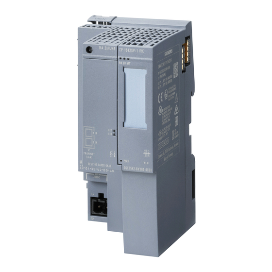
Page 115: Dimension Drawings
Dimension drawings All dimensions in the dimension drawings are in millimeters. Figure B-1 Front view of the CP CP 1542SP-1, CP 1542SP-1 IRC, CP 1543SP-1 Operating Instructions, 01/2017, C79000-G8976-C426-03... - Page 116 Dimension drawings Figure B-2 Side view (left) of the CP CP 1542SP-1, CP 1542SP-1 IRC, CP 1543SP-1 Operating Instructions, 01/2017, C79000-G8976-C426-03...
-
Page 117: Accessories
Accessories BusAdapter BusAdapter To connect to the Ethernet network, the CP requires a BusAdapter. A BusAdapter does not ship with the CP. Figure C-1 Example of a bus adapter, here BA SCRJ/RJ45 The CP supports the following bus adapters: ● BA 2×RJ45 PROFINET bus adapter with the following connectors: –... -
Page 118: Assignment Of The Ethernet Interface Of The Bus Adapter
– 1 x direct connection of the bus cable (FastConnect) Article number: 6ES7193-6AP40-0AA0 You will find further details in the manual /2/ (Page 119) and in the Siemens Industry Mall in Link: (https://mall.industry.siemens.com). Assignment of the Ethernet interface of the bus adapter Pinout of the Ethernet interface The table below shows the pin assignment of the Ethernet interface. -
Page 119: Documentation References
Documentation references Where to find Siemens documentation ● Article numbers You will find the article numbers for the Siemens products of relevance here in the following catalogs: – SIMATIC NET - Industrial Communication / Industrial Identification, catalog IK PI – SIMATIC - Products for Totally Integrated Automation and Micro Automation, catalog... - Page 120 Documentation references SIMATIC NET TeleControl Server Basic (Version V3) Operating Instructions Siemens AG Link: (https://support.industry.siemens.com/cs/ww/en/ps/15918/man) SIMATIC NET Industrial Ethernet Security Basics and Application Configuration Manual Siemens AG Link: (https://support.industry.siemens.com/cs/ww/en/ps/15326/man) SIMATIC NET TIM DNP3 System manual Siemens AG Link: (https://support.industry.siemens.com/cs/ww/en/ps/15940/man) SIMATIC NET...
-
Page 121: Index
Index Abbreviations/acronyms, 4 Hardware product version, 3 Article number, 3 IEC 60870-5-104 BusAdapter, 27 Device profile, 13 Protocol, 13 Image memory, 64 IPv4, 14 IPv6, 14 Conditional spontaneous, 72 Connection resources, 17 CPU firmware, 20 Cross references (PDF), 5 MAC address, 3 MIB, 100 Mirroring back, 62 Data buffering, 17... - Page 122 Index S7 connections - enable, 46 Safety notices, 29 Security, 15 Send buffer, 17, 64 Service & Support, 6 SIMATIC NET glossary, 6 Slot rules, 33 SMTPS, 86 SNMP, 15, 100 SNMPv3, 17 STARTTLS, 86 Static values, 64 STEP 7 version, 20 TCSB, 4 TeleControl Basic, 13 Telecontrol server, 4...
Need help?
Do you have a question about the ET 200SP and is the answer not in the manual?
Questions and answers