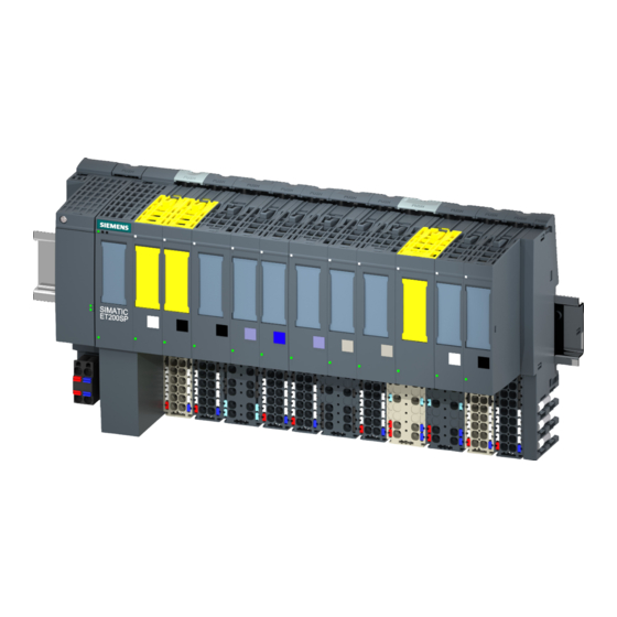
Siemens SIMATIC ET 200SP User Manual

Siemens SIMATIC ET 200SP User Manual

Open controller
Hide thumbs Also See for SIMATIC ET 200SP:
Table of Contents

Advertisement

Advertisement

Table of Contents
loading

Summary of Contents for Siemens SIMATIC ET 200SP

  • Page 2 ___________________ Preface ___________________ Documentation guide ___________________ SIMATIC Safety notes ___________________ Product overview ET 200SP Open Controller CPU 1515SP PC (F) ___________________ Installing ___________________ Connection Manual ___________________ Diagnostics, error and system alarm ___________________ Commissioning ___________________ Functions ___________________ Maintenance ___________________ Technical data ___________________ Accessories/spare parts ___________________...
  • Page 3 Note the following: WARNING Siemens products may only be used for the applications described in the catalog and in the relevant technical documentation. If products and components from other manufacturers are used, these must be recommended or approved by Siemens. Proper transport, storage, installation, assembly, commissioning, operation and maintenance are required to ensure that the products operate safely and without any problems.
  • Page 4: Preface

    Basic knowledge required The system must be operated and used by qualified staff only. The following knowledge is required: ● Installation guideline for SIMATIC ET 200SP ● Programming with STEP 7 ● PC based automation with an S7-1500 software controller and with WinCC Runtime Advanced ●...
  • Page 5 In order to protect plants, systems, machines and networks against cyber threats, it is necessary to implement – and continuously maintain – a holistic, state-of-the-art industrial security concept. Siemens’ products and solutions only form one element of such a concept. Customer is responsible to prevent unauthorized access to its plants, systems, machines and networks.
  • Page 6 This information is provided by the Siemens Industry Online Support in the Internet (http://www.siemens.com/automation/service&support). Industry Mall The Industry Mall is the catalog and order system of Siemens AG for automation and drive solutions on the basis of Totally Integrated Automation (TIA) and Totally Integrated Power (TIP).
  • Page 7 Preface CPU 1515SP PC (F) Manual, 05/2017, A5E32701806-AC...
  • Page 8: Table Of Contents

    Table of contents Preface ..............................4 Documentation guide ..........................11 Documentation on CPU 1515SP PC (F) ................14 Safety notes ............................15 Notes on use .......................... 17 Product overview ..........................18 Fail-safe option........................18 Properties ..........................19 Sample configuration ......................21 Components ...........................
  • Page 9 Table of contents Commissioning ............................. 49 Notes on commissioning ......................49 Initial commissioning ....................... 50 Initial configuration of an Open Controller ................53 Installing license keys ......................55 Windows Security Center ....................... 57 Switching CPU 1515SP PC (F) on/off ..................58 Functions ..............................
  • Page 10 Table of contents Technical data ............................. 101 10.1 Standards and approvals ..................... 101 10.2 Electromagnetic compatibility ....................105 10.3 Shipping and storage conditions ..................108 10.4 Mechanical and climatic ambient conditions ................ 108 10.5 Information on insulation, protection class, degree of protection and rated voltage ... 110 10.6 Use of the ET 200SP in zone 2 potentially explosive atmospheres ........
  • Page 11: Documentation Guide

    Documentation guide The documentation for the SIMATIC ET 200SP distributed I/O system is arranged into three areas. This arrangement enables you to access the specific content you require. Basic information The system manual describes in detail the configuration, installation, wiring and commissioning of the SIMATIC ET 200SP.
  • Page 12 You can download the product information free of charge from the Internet (https://support.industry.siemens.com/cs/us/en/view/73021864). Manual Collection ET 200SP The Manual Collection contains the complete documentation on the SIMATIC ET 200SP distributed I/O system gathered together in one file. You can find the Manual Collection on the Internet (http://support.automation.siemens.com/WW/view/en/84133942).
  • Page 13 ● Manuals, characteristics, operating manuals, certificates ● Product master data You can find "mySupport" - CAx Data in the Internet (http://support.industry.siemens.com/my/ww/en/CAxOnline). Application examples The application examples support you with various tools and examples for solving your automation tasks. Solutions are shown in interplay with multiple components in the system - separated from the focus in individual products.
  • Page 14: Documentation On Cpu 1515Sp Pc (F)

    You can find the SIMATIC Automation Tool on the Internet (https://support.industry.siemens.com/cs/ww/en/view/98161300). PRONETA With SIEMENS PRONETA (PROFINET network analysis), you analyze the plant network during commissioning. PRONETA features two core functions: ● The topology overview independently scans PROFINET and all connected components.
  • Page 15: Safety Notes

    Seal the cover with lead to protect the CFast card with the operating system of the CPU 1515SP PC (F) against unauthorized access. For more information on Industrial Security, refer to the Internet (http://www.siemens.com/industrialsecurity). CPU 1515SP PC (F) Manual, 05/2017, A5E32701806-AC...
  • Page 16 Safety notes Repairs WARNING Damage caused by opening the device Unauthorized opening of and improper repairs to the device may result in substantial damage to equipment or endanger the user. Only authorized personnel are permitted to repair the device. For additional information on repairs, see section Sending the device to customer service (Page 99).
  • Page 17: Notes On Use

    Safety notes 2.1 Notes on use Notes on use WARNING Hazards at an unprotected machine or plant According to the results of a risk analysis, hazards can occur at an unprotected machine. The hazards may lead to personal injury. According to the risk analysis, the risk of injury to persons can be countered with the following measures: •...
  • Page 18: Product Overview

    SIMATIC Safety - Configuring and Programming (http://support.automation.siemens.com/WW/view/en/54110126). You can find information on using the CPU 1505SP (F) software controller in the corresponding product manual (https://support.industry.siemens.com/cs/ww/en/view/109740725) and in the F product information (https://support.industry.siemens.com/cs/ww/en/view/109478599). CPU 1515SP PC (F) Manual, 05/2017, A5E32701806-AC...
  • Page 19: Properties

    Product overview 3.2 Properties Properties Article number 6ES7677-2xAxx-0xx0 The complete article number depends on the system version and the ordering option. View of the module The figure below shows the CPU 1515SP PC. Figure 3-1 CPU 1515SP PC with supplied accessories CPU 1515SP PC (F) Manual, 05/2017, A5E32701806-AC...
  • Page 20 Product overview 3.2 Properties Properties CPU 1515SP PC (F) is a PC based automation device in the design of the ET 200SP. It is used for control and visualization purposes. The supplied IPC DiagBase software provides basic diagnostics functions and supports you in handling the BIOS. CPU 1515SP PC (F) has the following technical properties: ●...
  • Page 21: Sample Configuration

    Product overview 3.3 Sample configuration System versions and ordering options System version SIMATIC software CFast card Article number WES7 E 32Bit CPU 1505SP V2.1 30 GB 6ES7677-2AA31-0EB0 WES7 P 64Bit CPU 1505SP V2.1 30 GB 6ES7677-2AA41-0FB0 (multitouch functionality) CPU 1505SP V2.1 & WinCC Runtime 30 GB 6ES7677-2AA41-0FK0 Adv.
  • Page 22 Product overview 3.3 Sample configuration Sample configuration The figure below shows an example configuration with CPU 1515SP PC (F). Figure 3-2 Example configuration with the CPU 1515SP PC (F) ① CPU 1515SP PC (F), I/O module, server module ② Mounting rail ③...
  • Page 23: Components

    Product overview 3.4 Components Components Components of the CPU 1515SP PC (F) The table below contains an overview of the components of the CPU 1515SP PC (F): Table 3- 1 Components of the CPU 1515SP PC Component Function Figure Mounting rail in accordance The mounting rail is the module carri- with EN 60715 er for the CPU 1515SP PC (F).
  • Page 24: Configuration Of The Devices

    Product overview 3.5 Configuration of the devices Configuration of the devices Front view Figure 3-3 Front view CPU 1515SP PC (F) ① Mounting rail release mechanism ② Labeling strips ③ Server module ④ Cooling fins ⑤ Strain relief ⑥ Reference labels CPU 1515SP PC (F) Manual, 05/2017, A5E32701806-AC...
  • Page 25: Operator Controls And Display Elements

    Product overview 3.6 Operator controls and display elements Operator controls and display elements Front view of the module The figure below shows the operator control and connection elements of the CPU 1515SP PC (F). Figure 3-4 View of the CPU 1515SP PC (F) ①...
  • Page 26 Product overview 3.6 Operator controls and display elements Slot for CFast card The operating system, Runtime software and project are installed on the supplied SIMATIC CFast card. The CFast card is the only mass storage device of the CPU 1515SP PC (F). Note Unauthorized access Seal the cover of the shaft with lead to protect the CFast card with the operating system of...
  • Page 27 Product overview 3.6 Operator controls and display elements Connector for supply voltage CPU 1515SP PC (F) has a 2-pole terminal for the power supply. The connection plug for the supply voltage is plugged in when the CPU is shipped from the factory.
  • Page 28: Scope Of Delivery

    ● Check packaging and contents for visible damage from transport. ● Check the delivery for completeness. Please inform your Siemens contact partner should you determine damages from transport or any irregularities. ● Keep the supplied documentation and licenses. They belong to the device and are the proof that you have purchased the software preinstalled on the CFast card.
  • Page 29 Product overview 3.7 Scope of delivery WARNING Electric shock and fire hazard from damaged device A damaged device can carry dangerous voltage and trigger a fire in the machine or plant. A damaged device has unpredictable properties and states. Death or severe injury could occur. Make sure that the damaged device is not installed and commissioned accidentally.
  • Page 30: Scope Of Delivery - System Version Wes7 E 32Bit 4Gb Ram

    Product overview 3.7 Scope of delivery 3.7.2 Scope of delivery - System version WES7 E 32Bit 4GB RAM Note The designation CPU 1515SP PC with the article number 6ES7677-2AA40-0AA0 is always on the device regardless of the order option. The following components are included in the scope of delivery of the CPU 1515SP PC: Order option CPU 1515SP PC CPU 1515SP PC...
  • Page 31 Product overview 3.7 Scope of delivery The following components are contained in the scope of delivery of the CPU 1515SP PC F: Order option CPU 1515SP PC F Article number 6ES7677-2FA31-0EB0 Strain relief with fixing screws Server module 30 GB CFast card with the following pre-installations: Windows Embedded Standard 7 E operating system •...
  • Page 32: Scope Of Delivery - System Version Wes7 P 64Bit 4Gb Ram

    Product overview 3.7 Scope of delivery 3.7.3 Scope of delivery - System version WES7 P 64Bit 4GB RAM Note The designation CPU 1515SP PC with the article number 6ES7677-2AA40-0AA0 is always on the device regardless of the order option. The following components are included in the scope of delivery of the CPU 1515SP PC: Order option CPU 1515SP PC CPU 1515SP PC + HMI...
  • Page 33: S7-1500 Software Controller Cpu 1505Sp F

    Product overview 3.7 Scope of delivery The following components are contained in the scope of delivery of the CPU 1515SP PC F: Order option CPU 1515SP PC F CPU 1515SP PC F + HMI Article number 6ES7677-2FA41-0FB0 6ES7677-2FA41- 0FK0 HMI 128PT •...
  • Page 34: Installing

    Installing Basics Introduction The CPU 1515SP PC (F) is an open operation resource. This means that you may only install it in enclosures, cabinets or electrical operating areas. These housings, cabinets or electrical operating areas must only be accessible with a key or tool. Access may only be possible for instructed or authorized personnel.
  • Page 35 Installing 4.1 Basics Mounting rail CPU 1515SP PC (F) is mounted on a mounting rail according to EN 60715 (35 × 7.5 mm and/or 35 × 15 mm). You must ground the mounting rail separately in the control cabinet. Exception: If you install the rail on grounded, zinc-plated mounting plates, there is no need to ground the rail separately.
  • Page 36: Cpu 1515Sp Pc (F)

    ● This is followed by BaseUnits BU..B (with dark-colored terminal box). ● The respective corresponding I/O modules can be connected to the BaseUnits. Suitable combinations of BaseUnits and I/O modules can be found in the ET 200SP System Manual (http://support.automation.siemens.com/WW/view/en/84133942). ● The server module completes the installation. Note Only install the CPU 1515SP PC (F) when the power supply is switched off.
  • Page 37: Hardware Configuration

    Installing 4.2 Hardware configuration Hardware configuration Maximum mechanical configuration As soon as one of the following rules applies, the maximum configuration has been reached: Table 4- 1 Maximum mechanical configuration Properties Rule Number of modules Horizontal mounting • – 0 to 60 °C ambient temperature: a maximum of 32 I/O modules and USB load –...
  • Page 38: Installing Cpu 1515Sp Pc (F)

    Installing 4.3 Installing CPU 1515SP PC (F) Installing CPU 1515SP PC (F) Requirements The mounting rail is fitted. Required tools 3 to 3.5 mm screwdriver (only to fix the strain relief and dismantle the BusAdapter) Fixing strain relief Fasten the strain relief at the upper and lower left side of the CPU 1515SP PC (F) with the supplied screws.
  • Page 39 Installing 4.3 Installing CPU 1515SP PC (F) Disassemble CPU 1515SP PC (F) The BaseUnits with the I/O modules are located to the left of the CPU 1515SP PC (F): 1. Switch off the supply voltage on the CPU. 2. Press the mounting rail release button on the first BaseUnit and, at the same time, move the CPU in parallel to the left until it comes off the remaining the module group.
  • Page 40: Connection

    Note Rules and regulations for operation Wiring Observe the information contained in the section in the system manual ET 200SP distributed I/O system (http://support.automation.siemens.com/WW/view/en/58649293) and in the function manual Designing interference-free controllers (http://support.automation.siemens.com/WW/view/en/59193566). NOTICE Fault caused by I/O devices The connection of I/O devices can lead to faults on the device.
  • Page 41: Terminal And Block Diagram

    Connection 5.2 Terminal and block diagram Terminal and block diagram Block diagram The figure below shows the block diagram of the CPU 1515SP PC (F). ① Switch X1 PN (LAN) PROFINET interface X1 ② Electronics PROFINET interface X1 Port 1 ③...
  • Page 42: Electrical Configuration

    Connection 5.3 Electrical configuration Electrical configuration Non-isolated configuration Note Unlike the distribution I/O system ET 200SP, only a non-isolated configuration is possible the CPU 1515SP PC (F). CPU 1515SP PC (F) Manual, 05/2017, A5E32701806-AC...
  • Page 43 Connection 5.3 Electrical configuration The figure below shows a CPU 1515SP PC (F) in the overall configuration with infeed from a TN-S system. The power supply supplies the CPU 1515SP PC (F) and the load circuits for the 24 V DC modules. With the CPU 1515SP PC (F) there is a fixed connection between the ground infeed terminal and the contact springs to the mounting rail.
  • Page 44: Connecting Devices To Networks

    Connection 5.4 Connecting devices to networks Connecting devices to networks The following options are available for integrating devices into existing or planned system environments and networks. Ethernet You can use the integrated Ethernet interface X2 PN/IE (LAN) (10/100/1000 Mbps) for communication and data exchange with automation devices, for example, SIMATIC S7.
  • Page 45 Connection 5.5 Securing cables Requirements ● The strain relief is fixed to the CPU. ● The CPU is installed. Procedure Secure the USB and PROFINET cables to the strain relief using cable ties. Figure 5-3 Secured cables CPU 1515SP PC (F) Manual, 05/2017, A5E32701806-AC...
  • Page 46: Diagnostics, Error And System Alarm

    Diagnostics, error and system alarm Status and error display LED display The figure below shows the LED displays of the CPU 1515SP PC (F). ① RUN/STOP LED (yellow/green LED) ② ERROR LED (red LED) ③ MAINT LED (yellow LED) ④ POWER LED (yellow/green LED) Figure 6-1 LED displays of the CPU 1515SP PC (F).
  • Page 47 Diagnostics, error and system alarm 6.1 Status and error display Meaning of the LED displays with active software controller CPU 1515SP PC (F) has a display of the current operating state and of the diagnostics status (three LEDs). The following table shows the meaning of the color combinations of the LED displays in connection with the software controller.
  • Page 48 Diagnostics, error and system alarm 6.1 Status and error display RUN/STOP LED ERROR LED MAINT LED Meaning Startup (CPU booting) Test of LEDs during startup, inserting a LED flashes red LED flashes yel- LED flashes module. yellow/green LED flashing test POWER LED Table 6- 2 POWER LED...
  • Page 49: Commissioning

    Commissioning Notes on commissioning WARNING Improper commissioning in hazardous areas Device failure or risk of explosion in hazardous areas. • Do not commission the device unless it is fully mounted and connected according to the specifications in the section Enhanced Write Filter (EWF) (Page 78). •...
  • Page 50: Initial Commissioning

    → The PWR LED lights up yellow first, then green. → The device carries out the hardware initialization. 4. Wait until the Siemens logo disappears from the screen. 5. Follow the instructions on the screen to configure the device NOTICE...
  • Page 51 Commissioning 7.2 Initial commissioning Initial commissioning an open controller The basic settings, user name, administrator password and IP address are prompted for during initial power-up of your CPU 1515SP PC (F). The device is then automatically set up for the operating system that is installed on the CFast card. Restart the device after the operating system has been set up.
  • Page 52 User "Operator" A user "Operator" with standard user rights is already created on the Windows system. The user is in a user group "SIEMENS TIA Engineer". This grants the user the rights to use the installed SIMATIC software products. To be able to use the CPU 1515SP PC (F) directly, the Windows "Autologon" is activated for the user "Operator".
  • Page 53: Initial Configuration Of An Open Controller

    Commissioning 7.3 Initial configuration of an Open Controller Initial configuration of an Open Controller Creating the configuration You have created a new project in the TIA Portal. To create the configuration in the TIA Portal, follow these steps: 1. Double-click "Add new device" in the project tree. 2.
  • Page 54 WinCC Runtime Advanced contains all the essential functions for operator control and monitoring of machinery or plants. Reference For more information on WinCC RT Advanced, refer to the WinCC Advanced V14 (http://support.automation.siemens.com/WW/view/en/109742297) system manual. CPU 1515SP PC (F) Manual, 05/2017, A5E32701806-AC...
  • Page 55: Installing License Keys

    CPU 1515SP PC (F). Open the software using the icon on the desktop or a menu command. 1. In the Windows start bar, select Start > All Programms > Siemens Automation > Automation License Manager. Automation License Manager 2.
  • Page 56 Automation License Manager For additional information on licenses, refer to the manual. You can find the manual for the CPU 1515SP PC (F) under Start > All Programs > Siemens Automation > Documentation and in the Internet (http://support.automation.siemens.com/WW/view/en/56956174). CPU 1515SP PC (F)
  • Page 57: Windows Security Center

    Commissioning 7.5 Windows Security Center Windows Security Center Warning from the Windows Security Center A warning from the Windows Security Center appears when you first switch on your device. The Security Center check the status of the device with regard to the main security aspects listed below.
  • Page 58: Switching Cpu 1515Sp Pc (F) On/Off

    Commissioning 7.6 Switching CPU 1515SP PC (F) on/off Switching CPU 1515SP PC (F) on/off Requirements Initial commissioning was successfully completed. Switching on the CPU 1515SP PC 1. Switch on the power supply of the CPU. The Boot Manager GRUB4DOS opens. 2.
  • Page 59: Functions

    Functions Monitoring functions Introduction CPU 1515SP PC (F) has monitoring functions that you can use with the corresponding software. The following display, monitoring and control functions are available. ● Temperature monitoring ● Monitoring of drives with SMART functionality ● Operating hours counter (information on the total runtime) SIMATIC IPC DiagBase The SIMATIC IPC DiagBase software is contained in the scope of delivery of the CPU 1515SP PC (F).
  • Page 60: Retentive Memory Nvram

    Functions 8.2 Retentive memory NVRAM Temperature monitoring Three thermistors monitor the temperature at multiple locations of the CPU 1515SP PC (F): ● Processor temperature ● Temperature in the vicinity of the RAM ICs/blocks ● Temperature of the basic module If one of the temperature values exceeds the set temperature threshold, the temperature monitoring triggers a temperature error.
  • Page 61: Bios Description

    Functions 8.3 BIOS description BIOS description 8.3.1 Introduction BIOS setup The BIOS setup is located in the BIOS ROM. The information is stored to the memory of the CPU 1515SP PC (F) via the system configuration. You can set the following using the Setup: ●...
  • Page 62: Starting Bios Setup

    Functions 8.3 BIOS description 8.3.2 Starting BIOS setup Start the setup program as follows: 1. Disconnect the device from the power supply and switch it on again (cold restart). The following screen appears in the default setting of the CPU 1515SP PC (F) after it is switched on: Figure 8-1 BIOS setup...
  • Page 63: Bios Setup Menus

    Functions 8.3 BIOS description 8.3.3 BIOS setup menus Overview of BIOS setup The menus and submenus are shown on the following pages. ① Menu bar ② Selectable submenu ③ Help window ④ Operating line Figure 8-2 Structure of the BIOS setup menus CPU 1515SP PC (F) Manual, 05/2017, A5E32701806-AC...
  • Page 64 Functions 8.3 BIOS description Menu structure ① In the menu bar , you can select between the following menu forms: [Information] [Main] [Advanced] [Security] [Power] [Boot] [Exit]. ② In the main window , various settings are displayed or submenus selected. ③...
  • Page 65: Information Menu

    Functions 8.3 BIOS description 8.3.3.1 Information menu This menu shows the versions of the device-specific functions. Keep this information at hand for Customer Support when you have technical questions regarding your system. Example Figure 8-3 Information menu CPU 1515SP PC (F) Manual, 05/2017, A5E32701806-AC...
  • Page 66: Main Menu

    Functions 8.3 BIOS description 8.3.3.2 Main menu Settings in the Main menu Figure 8-4 Main menu In the Main menu, you can use the [↑] up and [↓] down arrow keys to select between the following system setting fields: Array Meaning System Time Displaying and setting the current time...
  • Page 67: Advanced Menu

    Functions 8.3 BIOS description 8.3.3.3 Advanced menu Settings in the Advanced menu Figure 8-5 Advanced menu Entry Meaning Boot Configuration Configuring the boot settings IDE Configuration Configuring the devices Video Configuration Configuring the graphics parameters CPU Related setting Configuring CPU parameters AMD PBS Option Configuring interfaces "IDE Configuration"...
  • Page 68 Functions 8.3 BIOS description "Video Configuration" submenu Entry Meaning UMA Sharing Memory Size Setting the size of the work memory for the graphics processor. (256 MB) (Unified Memory Architecture; also Shared Memory) "CPU Related setting" submenu Entry Meaning SVM support Enabling (Enabled) or disabling (Disabled) Secure Virtual Machine functionality .
  • Page 69: Security Menu

    Functions 8.3 BIOS description 8.3.3.4 Security menu Settings in the Security menu Figure 8-6 Security menu To protect the CPU 1515SP PC (F) against unauthorized access, assign a password. Supervisor Pass- Installed Specific setup fields, including the Supervisor password, word can be modified by the user.
  • Page 70: Power Menu

    Functions 8.3 BIOS description 8.3.3.5 Power menu Settings in the Power menu Figure 8-7 Power menu In the Power menu, you specify the device reaction to a power failure and a Wake Event. Entry Meaning Wake on PME When activated (Enabled), the device switches itself on when a Power Management Event occurs.
  • Page 71: Boot Menu

    Functions 8.3 BIOS description 8.3.3.6 Boot menu Entries in the Boot menu Figure 8-8 Boot menu In this menu, you define the boot behavior of the device. Entry Meaning Quick Boot Enabling (Enabled) or disabling (Disabled). The device starts up faster when this option is enabled, because vari- ous hardware function tests are skipped.
  • Page 72 Functions 8.3 BIOS description Boot Device Priority > submenu "Boot Type Order" Entry Meaning Hard Disk Drive Setting the boot sequence of the group of drives Setting the boot sequence of the group of USB drives Others Setting the boot sequence of the group Others,, e.g. Remote Boot Device All connected boot-capable components and their boot position are displayed in this menu.
  • Page 73: Exit Menu

    Functions 8.3 BIOS description 8.3.3.7 Exit menu Settings in the Exit menu Figure 8-9 Exit menu The setup program is always terminated via the Exit menu. The menu is used to save or discard the changes made. Entry Meaning Exit Saving Changes Saves all changes and then starts the system with the new parame- ters.
  • Page 74: Bios Setup Default Settings

    Functions 8.3 BIOS description 8.3.4 BIOS setup default settings Documenting the device configuration If you change the default setting of the BIOS Setup, then enter this in the following table. This will ensure that values you set will be readily available if hardware changes are made later.
  • Page 75: Bios Update

    Functions 8.3 BIOS description Menu System parameters Default settings User settings Exit Exit Saving Change Standard Save Change Without Exit Exit Discarding Changes Load Optimal Defaults Load Custom Defaults Safe Custom Defaults Discard Changes 8.3.5 BIOS update With the SIMATIC IPC DiagBase software (included in scope of delivery), you can perform the following actions: ●...
  • Page 76: Power Options

    4. Switch off the power supply at the CPU 1515SP PC (F). 5. Connect the power supply. 6. Wait until the Siemens logo disappears. → The CPU 1515SP PC (F) restarts. NOTICE Overwriting of the Supervisor password during a BIOS update A BIOS update overwrites the password.
  • Page 77: Protective Functions For Data Carriers

    Functions 8.5 Protective functions for data carriers Protective functions for data carriers NOTICE Data loss The number of write cycles on CFast cards is limited due to technical reasons. To prevent data loss, the CFast card must therefore be provided with special protection. Use a write filter to lengthen of service life of the CFast card and avoid the CPU 1515SP PC (F).
  • Page 78: Enhanced Write Filter (Ewf)

    A Commit command will also be executed before the next reboot. The operating instructions for the SIMATIC Industrial PC: IPC EWF Manager (http://support.automation.siemens.com/WW/view/en/50867677) is available on the CPU 1515SP PC (F) under Start > All Programs > Siemens Automation > Documents > Manuals. CPU 1515SP PC (F)
  • Page 79 Functions 8.5 Protective functions for data carriers Console application ewfmgr.exe The application is called via the Windows command line (Command Prompt). The following functions are available, among others, for setting, switching on and switching off the EWF: Table 8- 2 Enhanced Write Filter functions Function Command...
  • Page 80 Functions 8.5 Protective functions for data carriers Special features when using the EWF NOTICE Data loss upon power failure and upon shutdown/restart If the EWF is active, all changes made on the C drive are lost after power failure and on shutdown/restart.
  • Page 81 Functions 8.5 Protective functions for data carriers Note Disabling automatic daylight saving changes In systems without central time management and with activated EWF, the time is advanced or set back by one hour in the daylight saving time or standard time period each time the system performs a cold or warm restart, due to the system-specific function for automatic daylight saving changes.
  • Page 82: File-Based Write Filter (Fbwf)

    Functions 8.5 Protective functions for data carriers 8.5.2 File-Based Write Filter (FBWF) Purpose and function The FBWF allows you to write-protect specific files and folders of a partition. FBWF is enabled by default on the CPU 1515SP PC (F). The FBWF is activated by means of the Windows console application fbwfmgr.exe. NOTICE Data loss If both write filters are activated, the EWF blocks direct write access of the FBWF.
  • Page 83 Functions 8.5 Protective functions for data carriers Rule for exclusion list The following sequence applies if you define exclusions for files and folders that do not yet exist: ● Defining exclusions ● Restart CPU 1515SP PC (F) ● Create file/folder Display of the partition size with activated FBWF The partition size displayed in the Explorer does not correspond with the actual size when the FBWF is active.
  • Page 84: Maintenance

    For additional information, please refer to the corresponding product documentation. SIMATIC IPC Service USB flash drive You can use the SIMATIC IPC Service USB flash drives for data backup and restore. You obtain these through the Siemens online ordering system (http://www.siemens.com/automation/mall). CPU 1515SP PC (F)
  • Page 85: Change Partitioning

    Maintenance 9.2 Change partitioning Change partitioning 9.2.1 Partitions in the delivery state Partitioning the CFast card The following partitions are set up on the CFast card by default: Partition Name 30 GB CFast card File system (WES7 E 32Bit/WES7 P 64Bit) SYSTEM 19.5 GB NTFS...
  • Page 86: Change Partitioning

    Maintenance 9.2 Change partitioning 9.2.2 Change partitioning If the capacities of the partitions are insufficient, you have the option with Windows 7 to change the size of the partitions (for example, drive C: extend and drive D: reduce). Free space must be available in order to extend the partition. You can recognize free space by the designation "Unallocated".
  • Page 87 Maintenance 9.2 Change partitioning To expand Partition C: you must delete Partition D: first. Right-click on Partition D: and select "Delete Volume..." Figure 9-2 Partition D: Delete The space which was occupied by Partition D: is now available for Partition C: . Figure 9-3 Partition D: cleared CPU 1515SP PC (F)
  • Page 88 Maintenance 9.2 Change partitioning Now right-click on Partition C: and select "Extend Volume...". Figure 9-4 Partition C: expand After selecting the option "Extend Volume...", the "Extend Volume Wizard" appears. Figure 9-5 Extend Volume Wizard CPU 1515SP PC (F) Manual, 05/2017, A5E32701806-AC...
  • Page 89 Maintenance 9.2 Change partitioning In the following window you have the option to expand Partition C: by all or part of the available memory. In our example we expand Partition C: by 500 MB. Figure 9-6 Select memory size When you have completed the steps of the wizard, the Computer Management window shows you the new division of the partition sizes.
  • Page 90 Maintenance 9.2 Change partitioning To reassign the unassigned memory to Partition D: right-click on the unassigned memory and select "New Simple Volume..." Figure 9-8 Recreate partition After selecting the option "New Simple Volume...", the "New Simple Volume Wizard" appears. Set the required memory size there. Figure 9-9 Select memory size CPU 1515SP PC (F)
  • Page 91 Maintenance 9.2 Change partitioning In the following window, select Drive D: Figure 9-10 Assign drive letter Specify the formatting for storing data on the partition. Figure 9-11 Specify formatting CPU 1515SP PC (F) Manual, 05/2017, A5E32701806-AC...
  • Page 92: Restoring The Delivery State

    Maintenance 9.3 Restoring the delivery state Once you have defined the formatting, an overview of your selected settings appears. Then click "Finish" to complete the process. The "Computer Management" window now shows the new partition sizes. Restoring the delivery state Introduction The entire image of your operating system and your Runtime software are located on the supplied Restore DVD.
  • Page 93 Maintenance 9.3 Restoring the delivery state Requirements To restore the original software of the CPU 1515SP PC (F), the following is required: ● A CFast card. Minimum size of the CFast card for the CPU 1515SP PC (F): – WES7 E 32Bit 4GB RAM: 8 GB –...
  • Page 94 Maintenance 9.3 Restoring the delivery state Restore delivery state of the CPU 1515SP PC (F) with the Restore DVD Before the restore 1. Switch off the power supply of the CPU. 2. Remove all USB devices from the CPU. 3. Connect a DVD drive with restore DVD to a USB interface of the CPU. 4.
  • Page 95: Restoring Delivery State Using Usb Stick

    Maintenance 9.4 Restoring delivery state using USB stick Restoring delivery state using USB stick Introduction You can use the Restore menu to create a bootable USB stick in order to restore the original software of the CPU 1515SP PC (F). Use the SIMATIC IPC Service USB FlashDrive (6AV7672-8JD02-0AA0) for the creation.
  • Page 96 Maintenance 9.4 Restoring delivery state using USB stick Restoring delivery state using USB stick Before the restore 1. Switch off the power supply of the CPU. 2. Remove all USB devices from the CPU. 3. Connect the Restore USB stick directly to the CPU. 4.
  • Page 97: Updating Software

    If you update the software, then always start the CPU 1515SP PC (F) in the GRUB menu in Windows mode (see Figure (Page 58)). Information on updating software can be found on the Internet (https://support.industry.siemens.com/cs/ww/en). HMI devices During the installation, make sure that you always use the latest drivers for the HMI devices used (SIMATIC Flat Panels).
  • Page 98: Windows Embedded Standard 7

    Maintenance 9.6 Windows Embedded Standard 7 Windows Embedded Standard 7 The Windows Embedded Standard 7 operating system is pre-installed on the CPU 1515SP PC (F). WES7 E 32Bit or WES7 P 64Bit are available depending on the order option. The WES7 P version supports multi-touch functionality (gesture control). Windows language packs English is available as the basic language for the installation of the Windows operating system.
  • Page 99: Sending The Device To Customer Service

    Maintenance 9.7 Sending the device to customer service Sending the device to customer service Before sending Note Back up data and remove memory cards Before you send in the CPU 1515SP PC (F) for repair: • Create a backup of your data. •...
  • Page 100: Removing And Inserting The Cfast Card

    Maintenance 9.8 Removing and inserting the CFast card Removing and inserting the CFast card Introduction CPU 1515SP PC (F) has one slot for a CFast card. On this card, you will find the operating system, your Runtime software and, after configuration, the project. Seal the cover for the CFast card to protect the system against unauthorized access.
  • Page 101: Technical Data

    Technical data 10.1 Standards and approvals Introduction The general technical specifications cover the following: ● The standards and test values which the CPU 1515SP PC (F) complies with and fulfils. ● The test criteria according to which the CPU 1515SP PC (F) was tested. Currently valid markings and approvals Note The currently valid markings and approvals are printed on the CPU 1515SP PC (F).
  • Page 102 ● 2004/108/EC "Electromagnetic Compatibility" (EMC Directive) ● 94/9/EC "Equipment and protective systems intended for use in potentially explosive atmospheres" (Explosion Protection Directive) The EC declarations of conformity are available for the responsible authorities at: Siemens AG Digital Factory Factory Automation DF FA AS DH AMB...
  • Page 103 Technical data 10.1 Standards and approvals cULus HAZ. LOC. approval Underwriters Laboratories Inc., complying with ● UL 508 (Industrial Control Equipment) ● CSA C22.2 No. 142 (Process Control Equipment) ● ANSI/ISA 12.12.01 ● CSA C22.2 No. 213 (Hazardous Location) APPROVED for use in Class I, Division 2, Group A, B, C, D Tx;...
  • Page 104 Technical data 10.1 Standards and approvals IECEx approval According to IEC 60079-15 (Explosive atmospheres - Part 15: Equipment protection by type of protection "n") and IEC 60079-0 (Explosive atmospheres - Part 0: Equipment - General requirements) Marking for Australia and New Zealand The ET 200SP distributed I/O system meets the requirements of the standard AS/NZS CISPR 16.
  • Page 105: Electromagnetic Compatibility

    ● Installation of the CPU 1515SP PC (F). in grounded control/switch cabinets ● Use of filters in the supply lines Reference The certificates for the markings and approvals can be found on the Internet under Service&Support (http://www.siemens.com/automation/service&support). 10.2 Electromagnetic compatibility Definition Electromagnetic compatibility (EMC) is the ability of an electrical installation to function satisfactorily in its electromagnetic environment without interfering with that environment.
  • Page 106 IEC 61000-4-4. 1 kV (signal cable < 30 m) High-energy single pulse (surge) according to IEC 61000-4-5 External protective circuit required (see function manual Designing interference-free controllers (http://support.automation.siemens.com/WW/view/en/59193566)) 2 kV (power supply cable) asymmetric coupling • DC with protective elements 2 kV (signal cable/data cable only >...
  • Page 107 Technical data 10.2 Electromagnetic compatibility Sinusoidal disturbance The following table shows the electromagnetic compatibility of the CPU 1515SP PC (F) with regard to sinusoidal interference. ● RF radiation Table 10- 3 Sinusoidal disturbance variables with RF radiation RF radiation according to IEC 61000-4-3/NAMUR 21 corresponds to degree of severity Electromagnetic RF field, amplitude-modulated...
  • Page 108: Shipping And Storage Conditions

    Technical data 10.3 Shipping and storage conditions 10.3 Shipping and storage conditions Introduction The CPU 1515SP PC (F) exceeds requirements in terms of shipping and storage conditions according to IEC 61131-2. The following information applies to modules that are shipped and/or stored in their original packaging.
  • Page 109 Technical data 10.4 Mechanical and climatic ambient conditions Mechanical ambient conditions The table below shows the mechanical ambient conditions in the form of sinusoidal oscillations. Table 10- 8 Mechanical ambient conditions Frequency band CPU 1515SP PC (F) 5 ≤ f ≤ 8.4 Hz 3.5 mm amplitude 8.4 ≤...
  • Page 110: Information On Insulation, Protection Class, Degree Of Protection And Rated Voltage

    Technical data 10.5 Information on insulation, protection class, degree of protection and rated voltage Climatic ambient conditions You may use the CPU 1515SP PC (F) under the following climatic, ambient conditions. Table 10- 10 Climatic ambient conditions Ambient conditions Permissible range Comments Temperature: For configuration with 32 I/O modules and 3 x...
  • Page 111: Use Of The Et 200Sp In Zone 2 Potentially Explosive Atmospheres

    Dynamic value: including ripple, for example, with three-phase bridge rectification 10.6 Use of the ET 200SP in zone 2 potentially explosive atmospheres See product information Use of subassemblies/modules in a Zone 2 Hazardous Area (http://support.automation.siemens.com/WW/view/en/19692172). CPU 1515SP PC (F) Manual, 05/2017, A5E32701806-AC...
  • Page 112: Module Data

    Technical data 10.7 Module data 10.7 Module data 10.7.1 CPU 1515SP PC, system version WES7 E 32Bit 4GB RAM CPU 1515SP PC, system version WES7 E 32Bit 4GB RAM 6ES7677-2AA31-0EB0 General information Product type designation CPU 1515SP PC HW release number FS06 Firmware version V2.1...
  • Page 113 Technical data 10.7 Module data 6ES7677-2AA31-0EB0 Memory Type of memory DDR3-SDRAM CFast memory card Yes; 30 GB flash memory SIMATIC memory card required Work memory Integrated (for program) 1 MB Integrated (for data) 5 MB Integrated (for ODK application) 10 MB Load memory Integrated (on PC mass storage medium) 320 MB...
  • Page 114 Technical data 10.7 Module data 6ES7677-2AA31-0EB0 2nd interface Interface hardware Number of ports RJ 45 (Ethernet) Yes; integrated 1000 Mbps Transmission rate, max. • Industrial Ethernet status LED • 3rd interface Interface hardware RS 485 Interface hardware RJ 45 (Ethernet) 100 Mbps Yes;...
  • Page 115: Cpu 1515Sp Pc F, System Version Wes7 E 32Bit 4Gb Ram

    Technical data 10.7 Module data 6ES7677-2AA31-0EB0 Dimensions Width 160 mm Height 117 mm Depth 75 mm Weights Weight, approx. 0.83 kg 10.7.2 CPU 1515SP PC F, system version WES7 E 32Bit 4GB RAM CPU 1515SP PC F, system version WES7 E 32Bit 4GB RAM 6ES7677-2FA31-0EB0 General information Product type designation...
  • Page 116 Technical data 10.7 Module data 6ES7677-2FA31-0EB0 Power Power consumption, max. 36 W; incl. ET 200SP modules and USB use Incoming power to the backplane bus 8.75 W Power loss Power loss, typ. 15 W; without ET 200SP modules and without USB use Memory Type of memory DDR3-SDRAM...
  • Page 117 Technical data 10.7 Module data 6ES7677-2FA31-0EB0 1st interface Interface hardware Number of ports integrated switch RJ 45 (Ethernet) Yes; via BusAdapter BA 2x RJ45 100 Mbps Transmission rate, max. • Industrial Ethernet status LED • 2nd interface Interface hardware Number of ports RJ 45 (Ethernet) Yes;...
  • Page 118: Cpu 1515Sp Pc, System Version Wes7 E 32Bit 4Gb Ram - Spare Part

    Technical data 10.7 Module data 6ES7677-2FA31-0EB0 Ambient temperature during storage / transport Min. -40 °C Max. 70 °C I/O / Options optional for additional mass storage SD card • Dimensions Width 160 mm Height 117 mm Depth 75 mm Weights Weight, approx.
  • Page 119 Technical data 10.7 Module data 6ES7677-2AA40-0AA0 Input current Current consumption (rated value) 1.5 A; full processor load, incl. ET 200SP modules and USB Current consumption (in no-load operation), typ. 0.6 A Inrush current, max. 4.7 A; rated value Power Power consumption, max. 36 W;...
  • Page 120 Technical data 10.7 Module data 6ES7677-2AA40-0AA0 1st interface Interface hardware Number of ports integrated switch RJ 45 (Ethernet) Yes; via BusAdapter BA 2x RJ45 100 Mbps Transmission rate, max. • Industrial Ethernet status LED • 2nd interface Interface hardware Number of ports RJ 45 (Ethernet) Yes;...
  • Page 121: Cpu 1515Sp Pc, System Version Wes7 P 64Bit 4Gb Ram

    Technical data 10.7 Module data 6ES7677-2AA40-0AA0 I/O / Options optional for additional mass storage SD card • Dimensions Width 160 mm Height 117 mm Depth 75 mm Weights Weight, approx. 0.83 kg 10.7.4 CPU 1515SP PC, system version WES7 P 64Bit 4GB RAM CPU 1515SP PC, system version WES7 P 64Bit 4GB RAM 6ES7677-2AA41-0FB0 General information...
  • Page 122 Technical data 10.7 Module data 6ES7677-2AA41-0FB0 Input current Current consumption (rated value) 1.5 A; full processor load, incl. ET 200SP modules and USB Current consumption (in no-load operation), typ. 0.6 A Inrush current, max. 4.7 A; rated value Power Power consumption, max. 36 W;...
  • Page 123 Technical data 10.7 Module data 6ES7677-2AA41-0FB0 Video interfaces Graphics interface 1x DVI-I 1st interface Interface hardware Number of ports integrated switch RJ 45 (Ethernet) Yes; via BusAdapter BA 2x RJ45 100 Mbps Transmission rate, max. • Industrial Ethernet status LED •...
  • Page 124: Cpu 1515Sp Pc F, System Version Wes7 P 64Bit 4Gb Ram

    Technical data 10.7 Module data 6ES7677-2AA41-0FB0 Ambient temperature during storage / transport Min. -40 °C Max. 70 °C I/O / Options optional for additional mass storage SD card • Dimensions Width 160 mm Height 117 mm Depth 75 mm Weights Weight, approx.
  • Page 125 Technical data 10.7 Module data 6ES7677-2FA41-0FB0 Power and voltage failure backup Power/voltage failure backup time 5 ms Input current Current consumption (rated value) 1.5 A; full processor load, incl. ET 200SP modules and USB Current consumption (in no-load operation), typ. 0.6 A Inrush current, max.
  • Page 126 Technical data 10.7 Module data 6ES7677-2FA41-0FB0 Interfaces Number of Industrial Ethernet interfaces Number of PROFINET interfaces Number of PROFIBUS interfaces Number of interfaces RS 485 1; via CM DP module Number of USB interfaces 3; 3x USB 2.0 front, 500 mA each – of which 2 x 500 mA and 1 x 100 mA simultaneously Number of SD card slots Video interfaces...
  • Page 127: Cpu 1515Sp Pc, System Version Wes7 E 64Bit 4Gb Ram - Spare Part

    Technical data 10.7 Module data 6ES7677-2FA41-0FB0 Ambient conditions Ambient temperature in operation Min. 0 °C Max. Up to 60 °C with max. 32 ET 200SP modules and 3x 100 mA USB load; up to 55 °C with max 64 ET 200SP modules and 2x max.
  • Page 128 Technical data 10.7 Module data 6ES7677-2AA40-0AA0 Operator controls Mode selector Supply voltage Type of supply voltage 24 V DC Low limit of permitted range (DC) 19.2 V High limit of permitted range (DC) 28.8 V Reverse polarity protection Power and voltage failure backup Power/voltage failure backup time 5 ms Input current...
  • Page 129 Technical data 10.7 Module data 6ES7677-2AA40-0AA0 Number of SD card slots Video interfaces Graphics interface 1x DVI-I 1st interface Interface hardware Number of ports integrated switch RJ 45 (Ethernet) Yes; via BusAdapter BA 2x RJ45 100 Mbps Transmission rate, max. •...
  • Page 130: Cpu 1515Sp Pc (F) + Hmi

    CPU 1505SP (F) is a PC-based controller of the SIMATIC S7-1500 Software Controller family. For more information about the CPU 1505SP (F), refer to the corresponding manual at (https://support.industry.siemens.com/cs/ww/en/view/109740725). For the CPU 1505SP F, also note the information in the F product information at (https://support.industry.siemens.com/cs/ww/en/view/109478599).
  • Page 131: Dimension Drawings

    Technical data 10.8 Dimension drawings 10.8 Dimension drawings 10.8.1 CPU 1515SP PC (F) This section contains a dimension drawing of the module mounted on a mounting rail. Always observe the specified dimensions for installation in cabinets. Dimension drawings of the CPU 1515SP PC (F). Figure 10-1 Dimension drawing of CPU 1515SP PC, front view CPU 1515SP PC (F)
  • Page 132 Technical data 10.8 Dimension drawings Figure 10-2 Dimension drawing of CPU 1515SP PC, side view CPU 1515SP PC (F) Manual, 05/2017, A5E32701806-AC...
  • Page 133: Accessories/Spare Parts

    Accessories/spare parts Ordering options and accessories for CPU 1515SP PC (F) Table A- 1 Order options for CPU 1515SP PC Description Article number System version WES7 E 32Bit 4GB RAM CPU 1515SP PC, 30 GB CFast card with pre-installed S7-1500 Software 6ES7677-2AA31-0EB0 Controller CPU 1505SP CPU 1515SP PC, 30 GB CFast card with pre-installed S7-1500 Software...
  • Page 134 CFast 16 GB Industrial Grade • 6ES7648-2BF10-0XK10 CFast 30 GB Industrial Grade • Online catalog Additional article numbers can be found on the Internet in the online catalog and online ordering system (http://www.siemens.com/automation/mall). CPU 1515SP PC (F) Manual, 05/2017, A5E32701806-AC...
  • Page 135: Abbreviations

    Abbreviations Abbreviation Term Meaning Alternating current Alternating current Automation License Manager Tool for managing license keys in STEP 7 BIOS Basic Input Output System Basic Input Output System. A set of important software rou- tines used after the startup of the CPU to load the operating system and to provide the routines for data exchange between hardware components.
  • Page 136 Abbreviations Abbreviation Term Meaning PELV Protective Extra Low Voltage PELV, previously called "extra low voltage with safe isolation", is a protective measure against electrical shock. See EN 50178. PROFINET Programming device Compact programming device which meets the special re- quirements of industry. The PG is fully equipped for program- ming SIMATIC PLCs.
  • Page 137: Troubleshooting

    Troubleshooting Problem Possible cause Remedy CPU 1515SP PC (F) is not working. CPU 1515SP PC (F) is not supplied Check the power supply. with current. CPU 1515SP PC (F) does not start. Feedback through USB devices. Use USB devices that comply with the USB 2.0 specification.
  • Page 138: Glossary

    Glossary Cold restart A startup procedure commencing when the CPU is switched on. Upon a cold restart, the system typically performs some basic hardware checks and then loads the operating system from the hard disk into the work memory. Controller Integrated hardware and software controlling the operation of a specific internal or I/O device (e.g.
  • Page 139 License key The license key is the electronic license stamp of a license. Siemens AG provides a license key for software that is protected by licensing laws.
  • Page 140 Glossary S.M.A.R.T Self-Monitoring, Analysis and Reporting Technology (SMART or S.M.A.R.T.) is an industry standard for storage media. It provides for permanent monitoring of relevant parameters and thus early recognition of pending defects. SATA Serial ATA. An interface for hard disk drives and optical drives with serial data transfer. SETUP (BIOS setup) A program used to determine information on the device configuration.

This manual is also suitable for:

Cpu 1515sp pc fCpu 1515sp pcHmi 128ptHmi 2048ptHmi 512pt

Table of Contents