Gefen EXT-DIGAUD-141 User Manual
Digital audio extender
Hide thumbs
Also See for EXT-DIGAUD-141:
- User manual (12 pages) ,
- User manual (10 pages) ,
- User manual (22 pages)
Table of Contents
Advertisement
Quick Links
Download this manual
See also:
User Manual
Advertisement
Table of Contents

Related Manuals for Gefen EXT-DIGAUD-141


Summary of Contents for Gefen EXT-DIGAUD-141
-
Page 1: Digital Audio
® Digital Audio Extender EXT-DIGAUD-141 USER MANUAL www.gefen.com... - Page 2 Notice Gefen, LLC reserves the right to make changes in the hard ware, packaging and any accompanying doc u men ta tion without prior written notice. Digital Audio Extender is a trademark of Gefen, LLC © 2010 Gefen, LLC, All Rights Reserved...
-
Page 3: Table Of Contents
TABLE OF CONTENTS Introduction Box Contents and Operation Notes Connecting the Digital Audio Extender Panel Layouts Link Cable Wiring Diagram Specifi cations Warranty... -
Page 4: Introduction
This unit will extend S/PDIF and TOSLINK digital audio devices up to 100 meters (330 feet). Place your digital audio components anywhere you want with Gefen’s Digital Audio Extender. It supports either S/PDIF or TOSLINK digital audio signals, which are commonly used to transmit stereo and multichannel (7.1, DTS, Dolby Digital, etc.) -
Page 5: Box Contents
BOX CONTENTS The Digital Audio Extender system consists of: (1) Digital Audio Extender (1) 5 VDC power supply (1) TOSLINK Cable (6 FT M-M) (1) User Manual OPERATION NOTES READ THESE NOTES BEFORE IN STALL ING OR OPERATING THE DIGITAL AUDIO EXTENDER SYSTEM Industry standard Category-5 (CAT5 or CAT5e) cables are used to link the Digital Audio Extender sender and receiver boxes together. -
Page 6: Connecting The Digital Audio Extender
CONNECTING THE DIGITAL AUDIO EXTENDER How to Connect the Digital Audio Extender System: 1- Connect your digital audio source’s outputs to the Digital Audio Extender sender unit’s audio inputs with either TOSLINK or S/PDIF cabling. Please see “Panel Layout” on page 4 for a list of connectors on the units. 2- Connect the Sender and Receiver units to one another on their RJ45 link connec- tor jacks using a single CAT5 cable. -
Page 7: Panel Layouts
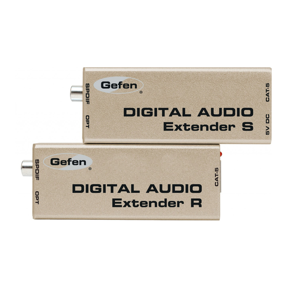
PANEL LAYOUTS Receiver (CAT5 link side) Sender (CAT5 link side) Receiver (output side) Sender (input side) Connections -- Digital Audio Extender Sender & Receiver units 1. RJ45 Jack -- CAT5 cable connection from Sender unit plugs in here 2. Power LED on Receiver -- indicates successful hookup between units 3. -
Page 8: Link Cable Wiring Diagram
LINK CABLE WIRING DIAGRAM... -
Page 9: Specifi Cations
SPECIFICATIONS Data Transmission Rate ................12.8 Mb/s Input/Output ..........S/PDIF (Digital Coax), Optical TOSLINK S/PDIF Performance (Digital Coax): ..............96 kHz Link Connector ................... RJ-45 Shielded Power Supply ....................5V DC Power Consumption: ..........5 Watts (max) per power supply. Dimensions ................1.2”H x 3.8”W x 1.4”D Shipping Weight .................... -
Page 10: Warranty
If equipment fails because of such defects and Gefen Inc. is notifi ed within two (2) years from the date of shipment, Gefen Inc. will, at its option, repair or replace the equipment, provided that the equipment has not been subjected to mechanical, electrical, or other abuse or modifi... - Page 12 Rev A1 20600 Nordhoff St Chatsworth, CA 91311 1-800-545-6900 818-772-9100 fax: 818-772-9120 www.gefen.com gsinfo@gefen.com...
Need help?
Do you have a question about the EXT-DIGAUD-141 and is the answer not in the manual?
Questions and answers