Table of Contents
Advertisement
Advertisement
Table of Contents

Related Manuals for HYT TC-780


Summary of Contents for HYT TC-780
-
Page 2: Table Of Contents
General ..........................1 Radio Overview........................2 Software Specifications.....................5 Circuit Description......................7 CPU Pins...........................12 TC-780 VHF Parts List 1 (Main Board Unit)..............17 TC-780 UHF Parts List 1 (Main Board Unit)..............38 TC-780 VHF/UHF Parts List 1 (Keyboard Unit) ..............66 Adjustment Description ....................67 Troubleshooting Flow Chart ...................75 Disassembly and Assembly for Repair ................79... -
Page 3: General
This equipment should be serviced by qualified technicians only. Use only HYT supplied or approved antenna. Turn off your radio prior to entering any area with a potentially explosive atmosphere. -
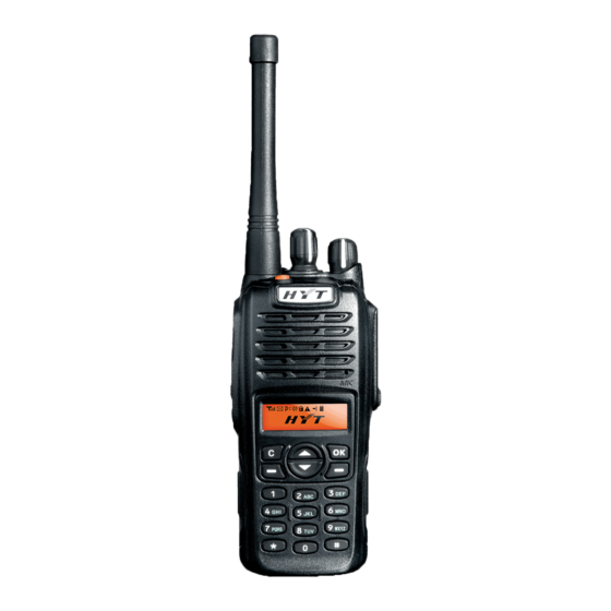
Page 4: Radio Overview
TC-780 Service Manual Radio Overview PTT ( Push -to- SK1 (Side Key 1) SK2 (Side Key 2) Antenna Talk ) Key Microphone Speaker LCD Display Function Keypad Numeric Keypad TK (Top Key) Channel Selector Radio On-Off / Volume Knob Control Knob... - Page 5 TC-780 Service Manual SK1 (Side Key 1) Programmable function key. SK2 (Side Key 2) Programmable function key. LCD Display Used to display radio status information. Function Keypad Exit key Use the Exit key to return to the previous menu.
- Page 6 TC-780 Service Manual TK (Top Key) Programmable function key. Channel Selector Knob Rotate the knob to select a desired channel. Radio On-Off / Volume Control Knob Rotate the knob clockwise to turn the radio on, and rotate the knob fully counter-clockwise until a click is heard to turn the radio off.
-
Page 7: Software Specifications
TC-780 Service Manual Software Specifications Specifications 256 Conventional Channels 32 Channel Groups 2-Tone / DTMF / HDC1200 / HDC2400 Encode & Decode ATIS Encode Priority Channel Scan When the radio operates in talkaround mode, the channel scan feature provides users with an easy way to monitor and join other channels. - Page 8 TC-780 Service Manual Man Down External Scrambler Patrol Record GPS Function Description 1. User Mode This mode is for normal operation by end users. 2. All Reset Mode Allows you to initialize tuning items, channel frequency, and conventional functions. See the Adjustment Description section for details.
-
Page 9: Circuit Description
TC-780 Service Manual Circuit Description Circuit Composition The overall circuit is composed of PLL-VCO circuit, transmit circuit, receive circuit, baseband processing circuit, power supply circuit, and MCU control circuit. Frequency Configuration The receiver section utilizes double conversion. The first IF is 44.85MHz and the second IF is 455 KHz. - Page 10 TC-780 Service Manual through a crystal filter ( XF401 ) to further remove spurious signals. IF Amplifier The first IF signal is amplified by Q412 and then enters U403 ( TA31136FN). The signal is mixed with the second local oscillator signal ( 44.395MHz ) again to create a 455 KHz second IF signal, which passes through a ceramic filter ( wide band: Z404;...
-
Page 11: Frequency Synthesizer
TC-780 Service Manual MIC Circuit and Modulation Circuit The audio signal from microphone is amplified by U204 after passing through the MIC control switch (Q616). The resulting signal is then amplified, pre-emphasized and etc by U203. Simultaneously, DTMF / 2-Tone / 5-Tone signallings generated by the MCU are amplified by U203, and then mixed with MIC audio signal, and finally fed to VCO for modulation. - Page 12 TC-780 Service Manual Figure 3 PLL Circuit Control Circuit The control circuit is comprised of MCU control circuit and power supply controller. U605 ( MCU ) operates at 9.8304 MHz. The CPU controls data transmission among receive circuit, transmit circuit, control circuit, display circuit and peripheral circuit.
- Page 13 TC-780 Service Manual to generate voltage including C5V, 5CNS, R5V, T5V. Figure 5 Power Switch Circuit Keypad and Display Circuit The display circuit is comprised of MCU ( U605 ), LCD module, keyboard, LED and other components. The backlight enable pin LED_EN is controlled by MCU. When the pin LED_EN is H, the backlight shall be turned on.
-
Page 14: Cpu Pins
TC-780 Service Manual CPU Pins Port Name Pin Name Function Remarks Automatic power control/Rx bandpass control. P94/DA1 APC/TV Adjust APC and Rx bandpass through DA (0-5V). DTMF/2-Tone/5-Tone/Beep output /ALARM output (DA P93/DA0 TONEO generates waveform). Cannot output from speaker. LCM data, display module LCM_SDI control data pin. - Page 15 TC-780 Service Manual Port Name Pin Name Function Remarks Used for Programmable port used for future future AUX5 development. develop- ment. (PWM) output CTCSS/CDCSS to P76/TA3O CTC_OUT VCO for modulation. GPS_In GPS input (PWM) output CTCSS/CDCSS to P74/TA2O CTC_PLL PLL for modulation.
- Page 16 TC-780 Service Manual Port Name Pin Name Function Remarks P56/ALE For programming only. P55/HOLD (PROG) 6 Ground through 47K resistor. AK2346 DIR. Control the I/O of data transmission. P54/HLDA AF_DIR H: output control word; L: read data. P53/BLCK AF_SCK AK2346 SCLK...
- Page 17 TC-780 Service Manual Port Name Pin Name Function Remarks Control audio power amplifier. P27/A7 PA_MUTE H: on; L: off. Narrow band control. P26/A6 N_CON H: narrow band path open; L: narrow band path closed. Red light control. P25/A5 LEDR H: on;...
- Page 18 TC-780 Service Manual Port Name Pin Name Function Remarks PTT detect. P02/D2 H: release; L: press. B indicates the second AK2346 (using the same P01/D1 AK2346B_DIR AK2346B register clock with the first AK2346) (for 5-Tone model) B indicates the second AK2346...
-
Page 19: Vhf Parts List 1 (Main Board Unit)
TC-780 Service Manual TC-780 VHF Parts List 1 (Main Board Unit) Material No. Description Qty. Ref No. Print No. 3101051020010 Chip capacitor 0402 1000PF K 50V (RoHS) C101 3101063900000 Chip capacitor 0603 39PF J 50V(RoHS) C102 3101051000020 Chip capacitor 0402 10PF J 50V (RoHS) - Page 20 TC-780 Service Manual Material No. Description Qty. Ref No. Print No. 3101051020010 Chip capacitor 0402 1000PF K 50V (RoHS) C148 3101054700010 Chip capacitor 0402 47PF J 50V(RoHS) C149 3101054710010 Chip capacitor 0402 470PF K 50V (RoHS) C150 3101051020010 Chip capacitor 0402 1000PF K 50V (RoHS)
- Page 21 TC-780 Service Manual Material No. Description Qty. Ref No. Print No. 3101051030020 Chip capacitor 0402 0.01UF K 25V(RoHS) C213 3101054720000 Chip capacitor 0402 4700PF K 50V (RoHS) C214 3101051040060 Chip capacitor 0402 0.1UF K 16V (RoHS) C215 3101051040060 Chip capacitor 0402 0.1UF K 16V (RoHS) C216 3101054740000 Chip capacitor 0402 0.47UF Z 6.3V(RoHS)
- Page 22 TC-780 Service Manual Material No. Description Qty. Ref No. Print No. 131 3101052730000 Chip capacitor 0402 0.027UF K 16V(RoHS) C260 132 3101051510000 Chip capacitor 0402 150PF(± 5%)(50V) (RoHS) C261 133 3101051040060 Chip capacitor 0402 0.1UF K 16V (RoHS) C262 134 3101052200010 Chip capacitor 0402 22PF J 50V (RoHS)
- Page 23 TC-780 Service Manual Material No. Description Qty. Ref No. Print No. 175 3101062400010 Chip capacitor 0603 24PF J 50V (RoHS) C415 176 3101051020010 Chip capacitor 0402 1000PF K 50V (RoHS) C416 177 3101051040060 Chip capacitor 0402 0.1UF K 16V (RoHS) C417 178 3104074750030 Tantalum capacitor 0805 4.7UF M 10V(RoHS)
- Page 24 TC-780 Service Manual Material No. Description Qty. Ref No. Print No. 219 3101051000020 Chip capacitor 0402 10PF J 50V (RoHS) C470 220 3101051500020 Chip capacitor 0402 15PF J 50V(RoHS) C471 221 3101051000020 Chip capacitor 0402 10PF J 50V (RoHS) C472...
- Page 25 TC-780 Service Manual Material No. Description Qty. Ref No. Print No. 263 3101051030020 Chip capacitor 0402 0.01UF K 25V(RoHS) C523 264 3101051020010 Chip capacitor 0402 1000PF K 50V (RoHS) C524 265 3101050900000 Chip capacitor 0402 9PF B 50V (RoHS) C525 266 3101051030020 Chip capacitor 0402 0.01UF K 25V(RoHS)
- Page 26 TC-780 Service Manual Material No. Description Qty. Ref No. Print No. 307 3101051500020 Chip capacitor 0402 15PF J 50V(RoHS) C627 308 3101052700000 Chip capacitor 0402 27PF J 50V (RoHS) C628 309 3101051020010 Chip capacitor 0402 1000PF K 50V (RoHS) C629 310 3101051030020 Chip capacitor 0402 0.01UF K 25V(RoHS)
- Page 27 TC-780 Service Manual Material No. Description Qty. Ref No. Print No. 351 3101051010030 Chip capacitor 0402 100PF J 50V(RoHS) C681 352 3101051010030 Chip capacitor 0402 100PF J 50V(RoHS) C682 353 3101051010030 Chip capacitor 0402 100PF J 50V(RoHS) C683 354 3101051010030 Chip capacitor 0402 100PF J 50V(RoHS)
- Page 28 TC-780 Service Manual Material No. Description Qty. Ref No. Print No. 395 3303020100080 Switching diode MA2S07700L (RoHS) D402 396 3303020100070 Switching diode MA2Z07700L (RoHS) D403 397 3399990000080 Zener diode EDZTE616.8B(RoHS) D405 398 3303020100080 Switching diode MA2S07700L (RoHS) D407 399 3303020100080 Switching diode MA2S07700L (RoHS)
- Page 29 TC-780 Service Manual Material No. Description Qty. Ref No. Print No. 439 3210306270000 Multi-layer chip inductor 0603 27nH (RoHS) L119 440 3210306270000 Multi-layer chip inductor 0603 27nH (RoHS) L120 441 3210306270000 Multi-layer chip inductor 0603 27nH (RoHS) L121 442 3221506601000 Chip ferrite bead 0603 600Ω± 25% (RoHS) L123 443 3213306561000 Multi-layer chip inductor 0603 0.56uH (RoHS)
- Page 30 TC-780 Service Manual Material No. Description Qty. Ref No. Print No. 483 3221506601000 Chip ferrite bead 0603 600Ω± 25% (RoHS) L605 484 3221506601000 Chip ferrite bead 0603 600Ω± 25% (RoHS) L606 485 3221506601000 Chip ferrite bead 0603 600Ω± 25% (RoHS) L607 486 3221506601000 Chip ferrite bead 0603 600Ω±...
- Page 31 TC-780 Service Manual Material No. Description Qty. Ref No. Print No. 527 3403008000070 Transistor DTC144EE(TL) (RoHS) Q609 528 3403008000070 Transistor DTC144EE(TL) (RoHS) Q610 529 3403008000010 Transistor DTC114EE(TL) (RoHS) Q611 530 3403008000010 Transistor DTC114EE(TL) (RoHS) Q612 531 3499000000150 Transistor UMC4(NTR) (RoHS)
- Page 32 TC-780 Service Manual Material No. Description Qty. Ref No. Print No. 571 3001051540020 Chip resistor 0402 150KΩ J 1/16W(RoHS) R134 572 3001051030000 Chip resistor 0402 10KΩ J 1/16W(RoHS) R135 573 3001054720000 Chip resistor 0402 4.7KΩ J 1/16W(RoHS) R136 574 3001053320000 Chip resistor 0402 3.3KΩ J 1/16W(RoHS) R137 575 3001051000000 Chip resistor 0402 10Ω...
- Page 33 TC-780 Service Manual Material No. Description Qty. Ref No. Print No. 615 3001051040010 Chip resistor 0402 100KΩ J 1/16W(RoHS) R233 616 3001054720000 Chip resistor 0402 4.7KΩ J 1/16W(RoHS) R234 617 3001051030000 Chip resistor 0402 10KΩ J 1/16W(RoHS) R235 618 3001051010000 Chip resistor 0402 100Ω J 1/16W(RoHS) R236 619 3001051010000 Chip resistor 0402 100Ω...
- Page 34 TC-780 Service Manual Material No. Description Qty. Ref No. Print No. 659 3001051030000 Chip resistor 0402 10KΩ J 1/16W(RoHS) R277 660 3001052230010 Chip resistor 0402 22KΩ J 1/16W(RoHS) R278 661 3001054720000 Chip resistor 0402 4.7KΩ J 1/16W(RoHS) R279 662 3001051030000 Chip resistor 0402 10KΩ J 1/16W(RoHS) R280 663 3001051040010 Chip resistor 0402 100KΩ...
- Page 35 TC-780 Service Manual Material No. Description Qty. Ref No. Print No. 703 3001063330000 Chip resistor 0603 33KΩ D 1/10W(RoHS) R420 704 3001051530000 Chip resistor 0402 15KΩ J 1/16W(RoHS) R421 705 3099080398000 Chip resistor 1206 0.39Ω J 1/4W(RoHS) R422 706 3099080398000 Chip resistor 1206 0.39Ω J 1/4W(RoHS) R423 707 3099080398000 Chip resistor 1206 0.39Ω...
- Page 36 TC-780 Service Manual Material No. Description Qty. Ref No. Print No. 747 3001054720000 Chip resistor 0402 4.7KΩ J 1/16W(RoHS) R473 748 3001052230010 Chip resistor 0402 22KΩ J 1/16W(RoHS) R474 749 3001052230010 Chip resistor 0402 22KΩ J 1/16W(RoHS) R475 750 3001052230010 Chip resistor 0402 22KΩ J 1/16W(RoHS) R476 751 3001052230010 Chip resistor 0402 22KΩ...
- Page 37 TC-780 Service Manual Material No. Description Qty. Ref No. Print No. 791 3001054720000 Chip resistor 0402 4.7KΩ J 1/16W(RoHS) R614 792 3001051050020 Chip resistor 0402 1MΩ J 1/16W(RoHS) R615 793 3001054730000 Chip resistor 0402 47KΩ J 1/16W(RoHS) R616 794 3001051050020 Chip resistor 0402 1MΩ J 1/16W(RoHS) R617 795 3001051030000 Chip resistor 0402 10KΩ...
- Page 38 TC-780 Service Manual Material No. Description Qty. Ref No. Print No. 835 3001051230000 Chip resistor 0402 12KΩ J 1/16W(RoHS) R669 836 3001051030000 Chip resistor 0402 10KΩ J 1/16W(RoHS) R670 837 3001051030000 Chip resistor 0402 10KΩ J 1/16W(RoHS) R671 838 3001052230010 Chip resistor 0402 22KΩ J 1/16W(RoHS) R672 839 3001052220000 Chip resistor 0402 2.2KΩ...
- Page 39 TC-780 Service Manual Material No. Description Qty. Ref No. Print No. 879 3005051020000 Resistor array 0402 1K*2 J 1/16W*2 (RoHS) RN620 B2G 880 3005051020010 Resistor array 0402 1K*4 J 1/16W*4 (RoHS) RN621 B3G 881 3005051020010 Resistor array 0402 1K*4 J 1/16W*4 (RoHS)
-
Page 40: Uhf Parts List 1 (Main Board Unit)
TC-780 Service Manual TC-780 UHF Parts List 1 (Main Board Unit) Material No. Description Qty. Ref No.Print No. Remarks 3101051020010 Chip capacitor 0402 1000PF K 50V (RoHS) C101 3101065600000 Chip capacitor 0603 56PF J 50V(RoHS) C102 U1:400-470MHz 3101064700000 Chip capacitor 0603 47PF J 50V(RoHS) - Page 41 TC-780 Service Manual Material No. Description Qty. Ref No.Print No. Remarks 3101054710010 Chip capacitor 0402 470PF K 50V(RoHS) C125 3104074750030 Tantalum capacitor 0805 4.7UF M 10V (RoHS) C126 3101054710010 Chip capacitor 0402 470PF K 50V(RoHS) C127 3101054710010 Chip capacitor 0402 470PF K 50V(RoHS)
- Page 42 TC-780 Service Manual Material No. Description Qty. Ref No.Print No. Remarks 3101054700010 Chip capacitor 0402 47PF J 50V (RoHS) U5:350-390MHz 3101050500010 Chip capacitor 0402 5PF B 50V(RoHS) C153 U1:400-470MHz 3101050200010 Chip capacitor 0402 2PF B 50V(RoHS) U2:450-520MHz 3101050500010 Chip capacitor 0402 5PF B 50V(RoHS)
- Page 43 TC-780 Service Manual Material No. Description Qty. Ref No.Print No. Remarks 3101054730000 Chip capacitor 0402 0.047UF K 10V(RoHS) C207 3104074750030 Tantalum capacitor 0805 4.7UF M 10V (RoHS) C208 3101051040060 Chip capacitor 0402 0.1UF K 16V(RoHS) C209 3101051500020 Chip capacitor 0402 15PF J 50V (RoHS)
- Page 44 TC-780 Service Manual Material No. Description Qty. Ref No.Print No. Remarks 3101051230000 Chip capacitor 0402 0.012UF K 25V (RoHS) C254 3101051050000 Chip capacitor 0402 1UF K 6.3V (RoHS) C255 3101053930000 Chip capacitor 0402 0.039UF K 10V(RoHS) C256 3101052210010 Chip capacitor 0402 220PF K 50V (RoHS)
- Page 45 TC-780 Service Manual Material No. Description Qty. Ref No.Print No. Remarks 3101054710010 Chip capacitor 0402 470PF K 50V(RoHS) C405 3101054710010 Chip capacitor 0402 470PF K 50V(RoHS) C406 3101051040060 Chip capacitor 0402 0.1UF K 16V(RoHS) C407 3101061210000 Chip capacitor 0603 120PF J 50V(RoHS)
- Page 46 TC-780 Service Manual Material No. Description Qty. Ref No.Print No. Remarks C433 U1:400-470MHz U2:450-520MHz 3101061500010 Chip capacitor 0603 15PF J 50V(RoHS) U5:350-390MHz 3101060100010 Chip capacitor 0603 1PF B 50V(RoHS) C434 U1:400-470MHz U2:450-520MHz 3101060400010 Chip capacitor 0603 4PF B 50V(RoHS) U5:350-390MHz 3101065690000 Chip capacitor 0603 5.6PF C 50V(RoHS)
- Page 47 TC-780 Service Manual Material No. Description Qty. Ref No.Print No. Remarks 3101064710000 Chip capacitor 0603 470PF K 50V (RoHS) U5:350-390MHz 3101053900000 Chip capacitor 0402 39PF J 50V(RoHS) C452 U1:400-470MHz 3101053900000 Chip capacitor 0402 39PF J 50V(RoHS) U2:450-520MHz 3101056800000 Chip capacitor 0402 68PF J 50V(RoHS)
- Page 48 TC-780 Service Manual Material No. Description Qty. Ref No.Print No. Remarks 3101050500010 Chip capacitor 0402 5PF B 50V(RoHS) U2:450-520MHz 3101051200020 Chip capacitor 0402 12PF J 50V(RoHS) U5:350-390MHz 3199052790000 Chip capacitor 0402 2.7PF B 50V(RoHS C472 U1:400-470MHz 3199052790000 Chip capacitor 0402 2.7PF B 50V(RoHS)
- Page 49 TC-780 Service Manual Material No. Description Qty. Ref No.Print No. Remarks 3101051020010 Chip capacitor 0402 1000PF K 50V (RoHS) C509 U1:400-470MHz 3101051020010 Chip capacitor 0402 1000PF K 50V (RoHS) U2:450-520MHz 3101054710010 Chip capacitor 0402 470PF K 50V(RoHS) U5:350-390MHz 3101058200000 Chip capacitor 0402 82PF J 50V (RoHS)
- Page 50 TC-780 Service Manual Material No. Description Qty. Ref No.Print No. Remarks 3101053300000 Chip capacitor 0402 33PF J 50V(RoHS) U2:450-520MHz 3101056800000 Chip capacitor 0402 68PF J 50V(RoHS) U5:350-390MHz 3101054700010 Chip capacitor 0402 47PF J 50V (RoHS) C536 U1:400-470MHz 3101052700000 Chip capacitor 0402 27PF J 50V (RoHS)
- Page 51 TC-780 Service Manual Material No. Description Qty. Ref No.Print No. Remarks 3101051050000 Chip capacitor 0402 1UF K 6.3V (RoHS) C635 3101052700000 Chip capacitor 0402 27PF J 50V (RoHS) C636 3101051020010 Chip capacitor 0402 1000PF K 50V (RoHS) C637 3101051030020 Chip capacitor 0402 0.01UF K 25V (RoHS)
- Page 52 TC-780 Service Manual Material No. Description Qty. Ref No.Print No. Remarks 3101051010030 Chip capacitor 0402 100PF J 50V(RoHS) C703 3101051010030 Chip capacitor 0402 100PF J 50V(RoHS) C704 3101051010030 Chip capacitor 0402 100PF J 50V(RoHS) C706 3101052230000 Chip capacitor 0402 0.022UF K 16V(RoHS)
- Page 53 TC-780 Service Manual Material No. Description Qty.Ref No.Print No. Remarks 3303020100020 Switching diode MA2S11100L (RoHS) D115 3303030300000 Schottky barrier diode D202 RB706F-40(T106) SOT-323(RoHS) 3303030300000 Schottky barrier diode D203 RB706F-40(T106) SOT-323(RoHS) 3303020100060 Switching diode MA3J74200L 30V 30mA (RoHS) D204 3303020100020 Switching diode MA2S11100L (RoHS)
- Page 54 TC-780 Service Manual Material No. Description Qty. Ref No.Print No. Remarks Bobbin inductor 1206 33nH (RoHS) 3210108330000 U5:350-390MHz 3213306332000 Multi-layer chip inductor 0603 3.3uH (RoHS) L106 3210108230010 Bobbin inductor 1206 23nH(RoHS) L107 U1:400-470MHz 3210108170000 Bobbin inductor 1206 17nH(RoHS) U2:450-520MHz Bobbin inductor 1206 33nH (RoHS)...
- Page 55 TC-780 Service Manual Material No. Description Qty. Ref No.Print No. Remarks 3210107221000 Bobbin inductor 0805 220nH (RoHS) L409 3231351640000 Air-core inductor E2-0.35*1.6*4TL(RoHS) L410 3231351640000 Air-core inductor E2-0.35*1.6*4TL(RoHS) L411 3231351640000 Air-core inductor E2-0.35*1.6*4TL(RoHS) U2:450-520MHz 3231351650000 Air-core inductor E2-0.35*1.6*5TL(RoHS) U5:350-390MHz 3231351640000 Air-core inductor E2-0.35*1.6*4TL(RoHS)
- Page 56 TC-780 Service Manual Material No. Description Qty. Ref No.Print No. Remarks 3221506601000 Chip ferrite bead 0603 600Ω± 25% (RoHS) L702 3499000000140 Transistor 2SK508-K52-T1B-A (RoHS) Q101 3499000000150 Transistor UMC4(NTR) /PNP(RoHS) Q102 3499000000140 Transistor 2SK508-K52-T1B-A (RoHS) Q103 3403003000060 Transistor 2SC4617TLS (RoHS) Q104 3401002000990 Transistor 2SC5108-Y(TE85L.F) (RoHS)
- Page 57 TC-780 Service Manual Material No. Description Qty. Ref No.Print No. Remarks 3403008000010 Transistor DTC114EE(TL) (RoHS) Q612 3403008000050 Transistor DTC114YE(TL) (RoHS) Q615 3503010000010 FET 2SJ243-T1-A P-channel (RoHS) Q616 3503040000010 FET UPA672T-T1-A N-channel (RoHS) Q618 3403002000000 Transistor 2SB1132FD5T100R(RoHS) Q701 3403003000060 Transistor 2SC4617TLS (RoHS)
- Page 58 TC-780 Service Manual Material No. Description Qty. Ref No.Print No. Remarks 3001055600000 Chip resistor 0402 56Ω J 1/16W(RoHS) U5:350-390MHz 3001051000000 Chip resistor 0402 10Ω J 1/16W(RoHS) R130 3001051030000 Chip resistor 0402 10KΩ J 1/16W(RoHS) R131 U1:400-470MHz 3001051530000 Chip resistor 0402 15KΩ J 1/16W(RoHS)
- Page 59 TC-780 Service Manual Material No. Description Qty. Ref No.Print No. Remarks 3001051030000 Chip resistor 0402 10KΩ J 1/16W(RoHS) R219 3001054720000 Chip resistor 0402 4.7KΩ J 1/16W(RoHS) R220 3001051530000 Chip resistor 0402 15KΩ J 1/16W(RoHS) R221 3001053330010 Chip resistor 0402 33KΩ J 1/16W(RoHS)
- Page 60 TC-780 Service Manual Material No. Description Qty. Ref No.Print No. Remarks 3001059130000 Chip resistor 0402 91KΩ F 1/16W(RoHS) R260 3001050000000 Chip resistor 0402 0Ω J 1/16W(RoHS) R261 3001052230010 Chip resistor 0402 22KΩ J 1/16W(RoHS) R262 3001051840000 Chip resistor 0402 180KΩ J 1/16W(RoHS)
- Page 61 TC-780 Service Manual Material No. Description Qty. Ref No.Print No. Remarks 3001052230010 Chip resistor 0402 22KΩ J 1/16W(RoHS) R305 3001051040010 Chip resistor 0402 100KΩ J 1/16W(RoHS) R306 3001052230010 Chip resistor 0402 22KΩ J 1/16W(RoHS) R307 3001050000000 Chip resistor 0402 0Ω J 1/16W(RoHS)
- Page 62 TC-780 Service Manual Material No. Description Qty. Ref No.Print No. Remarks 3001051020010 Chip resistor 0402 1KΩ J 1/16W(RoHS) R441 3001051040010 Chip resistor 0402 100KΩ J 1/16W(RoHS) R442 3001054740000 Chip resistor 0402 470KΩ J 1/16W(RoHS) R445 U1:400-470MHz 3001051040010 Chip resistor 0402 100KΩ J 1/16W(RoHS)
- Page 63 TC-780 Service Manual Material No. Description Qty. Ref No.Print No. Remarks 1011 3001050000000 Chip resistor 0402 0Ω J 1/16W(RoHS) R472 U1:400-470MHz 1012 3001052200000 Chip resistor 0402 22Ω J 1/16W(RoHS) U2:450-520MHz 1013 3001050000000 Chip resistor 0402 0Ω J 1/16W(RoHS) U5:350-390MHz 1014 3001054720000 Chip resistor 0402 4.7KΩ...
- Page 64 TC-780 Service Manual Material No. Description Qty. Ref No.Print No. Remarks 1055 3001052220000 Chip resistor 0402 2.2KΩ J 1/16W(RoHS) R602 1056 3001054730000 Chip resistor 0402 47KΩ J 1/16W(RoHS) R603 1057 3001054720000 Chip resistor 0402 4.7KΩ J 1/16W(RoHS) R604 1058 3001056840000 Chip resistor 0402 680KΩ...
- Page 65 TC-780 Service Manual Material No. Description Qty. Ref No.Print No. Remarks 1099 3001054730000 Chip resistor 0402 47KΩ J 1/16W(RoHS) R652 1100 3001051810010 Chip resistor 0402 180Ω J 1/16W(RoHS) R654 1101 3001051020010 Chip resistor 0402 1KΩ J 1/16W(RoHS) R656 1102 3001052210000 Chip resistor 0402 220Ω...
- Page 66 TC-780 Service Manual Material No. Description Qty. Ref No.Print No. Remarks 1143 3005051020010 Resistor array 0402 1K*4 J 1/16W*4 (RoHS) RN606 1144 3005051020000 Resistor array 0402 1K*2 J 1/16W*2 (RoHS) RN607 1145 3005051020010 Resistor array 0402 1K*4 J 1/16W*4 (RoHS)
- Page 67 TC-780 Service Manual Material No. Description Qty. Ref No.Print No. Remarks 1187 3701016850010 TCXO 16.8MHz 5V DSA535SA(5×3.2)(RoHS) X101 1188 3701041940010 Crystal 4.194304MHz(11.8*5.5*2.5) X201 DSX151GAL(RoHS) 1189 3702368630020 Crystal 3.6864MHz DSX151GA(11.8×5.5)(RoHS) X202 1190 3701443940010 Crystal oscillator 44.395MHz± 10PPm X401 NX3225DA (RoHS) 1191 3701098340010 Crystal 9.8304MHz DSX530GA(5×3.2)(RoHS)
-
Page 68: Vhf/Uhf Parts List 1 (Keyboard Unit)
TC-780 Service Manual TC-780 VHF/UHF Parts List 1 (Keyboard Unit) No. Material No. Description Qty. Ref No. Print No. 1 3001053910000 Chip resistor 0402 390Ω J 1/16W (RoHS) R702 2 3101051020010 Chip capacitor 0402 1000PF K 50V (RoHS) C717 3 3101051020010... -
Page 69: Adjustment Description
TC-780 Service Manual Adjustment Description Required Test Instruments Radio communication test set 1 set Scanner 1 set 3A /10V power supply 1 set Digital voltmeter 1 set 3A ammeter 1 set Preparation All Reset 1) Enter the Mode Turn on the radio while holding down and SK1, and then release the keys to enter all reset mode. -
Page 70: Adjustment Procedures
TC-780 Service Manual Measurement Adjustment Specifications/ Item Condition Test Termin Remarks Part Method Instrument 1. Setting 1. Power supply 2. Tx VCO 1. CH: Tx high. 3.6V± 0.1V Digital Lock TC114 Voltmeter >0.4V 2. CH: Tx low. Check Voltage 3. Rx VCO 1. - Page 71 TC-780 Service Manual select an adjustment item and save the adjustment value of the previous item. When adjusting Tx items, LED glows red; when adjusting Rx items, LED glows green 5) Save an Adjustment Value After adjustment is completed, you need to press to save the adjustment value and go to another adjustment item.
- Page 72 TC-780 Service Manual None 20KHZ None 20KHZ None 20KHZ None 12.5KHZ None 12.5KHZ None 12.5KHZ 67HZ 25KHZ 254.1HZ 25KHZ 25KHZ 25KHZ 2-TONE 25KHZ 5-TONE 25KHZ None 25KHZ Operations and Objectives Transmitter Test Item Condition Method Objective Instrument Power in tuning...
- Page 73 TC-780 Service Manual CTCSS Enter the adjustment Radio PTT (up) Adjust frequency (67.0Hz) mode and select an item. Communication SK1 (down) deviation to 750Hz, Low Frequency Adjust point 3 of wide Test Set 600Hz, 400Hz for Deviation band, point 1 of medium...
- Page 74 TC-780 Service Manual MSK Deviation Enter the adjustment PTT (up) Adjust frequency (MSK Dev) mode and select an item. SK1 (down) deviation to The radio transmits 2.5± 0.2KHz, (disable DTMF, MIC, the Channel 2.0± 0.2KHz, 2-Tone, CTCSS/CDCSS). Selector 1.6± 0.2KHz for wide,...
- Page 75 TC-780 Service Manual Receiver Test Item Condition Method Objective Instrument Bandpass Waveform Enter the adjustment Scanner PTT (up) Adjust the bandpass mode and select the Rx Bandpass Test SK1 (down) waveform to: Sensitivity item. Adjust Fixture point 5 of wide band.
- Page 76 TC-780 Service Manual SQL Value of Normal Enter the adjustment Radio Save Adjust the level Squelch Open mode and select an Communication to -120dBm and (SqlNorOpen) item. Adjust point 5 of Test Cable press PTT to wide band, point 1 of Audio Test save.
-
Page 77: Troubleshooting Flow Chart
TC-780 Service Manual Troubleshooting Flow Chart... - Page 78 TC-780 Service Manual...
- Page 79 TC-780 Service Manual Transmit Circuit No output power Power supply Check power works well? supply circuit The current is Control voltage is Check Q607 normal? normal? High Check transistor, Check drive offset voltage & stage low pass network Repair the...
-
Page 80: Receive Circuit
TC-780 Service Manual Receive Circuit No receive Power Control Supply of audio IC voltage PA_MUTE Replace Q615 is normal? is normal? Replace U609 Baseband Baseband IC Replace IC outputs inputs normally? AK2346 normally? U403 outputs Check U201 normally? Check volume... -
Page 81: Disassembly And Assembly For Repair
TC-780 Service Manual Disassembly and Assembly for Repair Disassemble the Radio Case 1. Remove the Radio On-Off/Volume Control knob and Channel Selector knob 2. Lift the chassis by its bottom and pull it out of the radio case Figure 1 Disassemble the Speaker 1. - Page 82 TC-780 Service Manual Disassemble the Transmit and Receive Units 1. Screw out the waterproof ring , the nut , and screws locking the keypad PCB, shown in figure 3. Figure 3 2. Rotate the keypad PCB module for 180 degrees, and then remove FPC...
- Page 83 TC-780 Service Manual Figure 5 Precautions for Assembly Assemble the Radio Case and Chassis 1. Make sure the waterproof cushion surrounding the chassis is well fitted into the slot of the chassis. 2. Correctly position and assemble the speaker on the radio case Note: Make sure that the speaker is fully assembled into the radio case.
- Page 84 TC-780 Service Manual Figure 6...
-
Page 85: Exploded View
TC-780 Service Manual Exploded View... -
Page 86: Parts List 2
TC-780 Service Manual TC-780 Parts List 2 Material No. Description Qty. 6000135000000 PTT key cover (RoHS) 6100068000000 PTT key (silica rubber) (RoHS) 6100319000000 Emergency key (silica rubber) (RoHS) 7500210000000 Adhesive tape, light guide 3M(9448) (RoHS) 6000609000000 Light guide (RoHS) Felt, speaker PES+PBO(U500PBO) ¢40.0 (RoHS) 7400208000000 Speaker 20Ω... - Page 87 TC-780 Service Manual 6000680000000 Battery latch (RoHS) 7000036000000 Spring (RoHS) 6000612000000 Front cover PC(EXL9330)+PMMA(CP-61) (RoHS) 6100317000000 Numeric keypad (RoHS)
-
Page 88: Packing
TC-780 Service Manual Packing... -
Page 91: Uhf Pcb View
TC-780 UHF PCB View (Main Board Unit) Top Layer... -
Page 95: Tc-780 Block Diagram
TC-780 Block Diagram TC-780 Block Diagram Pre AMP Drive AMP ANT SW final AMP U604 PLL IC Q404 Q409 Q401.Q402 U101 Data SAVE D403 U603 D406 5CNS 16.8MHz Q108 U602 X101 F601 2SA1745 Q606 Q109 ANT SW Q603 Q102 D407... -
Page 96: Vhf Schematic Diagram
TC-780 VHF Schematic Diagram (PLL & VCO Unit) PLL&VCO Circuit of Main Board C149 C149 L122 L122 Q111 Q111 D113 D113 C150 C150 C154 C154 L120 L120 C183 C183 C151 C151 MA2S077 MA2S077 470p 470p DTA114EE DTA114EE D114 D114 C156... - Page 97 TC-780 VHF Schematic Diagram (Power Unit) POWER Circuit of Main Board Q601 Q601 2SA1745 2SA1745 J601 J601 C605 C605 1000pF 1000pF BATTSEL L601 L601 U601 U601 F601 F601 BLM18AG601SN1 BLM18AG601SN1 XC6201T302PR XC6201T302PR R601 R601 VOUT J604 J604 R620 R620 FUSE...
- Page 98 TC-780 VHF Schematic Diagram (MCU Unit) MCU Circuit of Main Board R642 R642 AF_DIO U610 U610 R622 R622 SAVE HOLD R659 R659 P_CON TP629 TP629 AT25256A/AT24C512 AT25256A/AT24C512 Pin42 Pin42 R623 R623 LED_EN U606 U606 SWB+ EECLK AT25256A/AT24C512 AT25256A/AT24C512 EEP_SI R626...
- Page 99 TC-780 VHF Schematic Diagram (Tx/Rx Unit) TX/RX Circuit of Main Board C444 C444 C445 C445 C447 C447 J401 J401 D406 D406 1.5PF 1.5PF ANTENNA ANTENNA MA2Z077 MA2Z077 R431 R431 C437 C437 C442 C442 L436 L436 L437 L437 L438 L438 82PF...
- Page 100 TC-780 VHF Schematic Diagram (AFAMP & EXT Unit) AFAMP&EXT Interface Circuit of Main Board C685 C685 47u/16V 47u/16V R666 R666 470k 470k U609 U609 C680 C680 C679 C679 C678 C678 C677 C677 C676 C676 C675 C675 C674 C674 C673 C673...
- Page 101 TC-780 VHF Schematic Diagram (Baseband Unit) Baseband Circuit of Main Board VOL_OUT AUDIO_AMP R305 R305 R220 R220 R290 R290 C216 C216 5CNS 4.7k 4.7k 0.1uF 0.1uF R204 R204 R207 R207 R208 R208 R211 R211 R212 R212 C209 C209 R210 R210 0.1uF...
- Page 102 TC-780 VHF Schematic Diagram (LCD & Keyboard Unit) LCD&Keyboard Circuit of Main Board LCD&LCM 128*16 LCD&LCM 128*16 J701 J701 L701 L701 Q701 Q701 R706 R706 2SB1132 2SB1132 BLM18AG601SN1 BLM18AG601SN1 SWB+ TP716 TP716 TP717 TP717 TP718 TP718 TP719 TP719 C717 C717...
-
Page 103: Uhf Schematic Diagram
TC-780 UHF Schematic Diagram (Tx/Rx Unit) TX/RX Circuit of Main Board C444 C444 C445 C445 C447 C447 J401 J401 D406 D406 1.5p 1.5p ANTENNA ANTENNA C520 C520 C526 C526 R431 R431 C437 C437 C442 C442 RF AMP 3.6p 3.6p 100p... - Page 104 TC-780 UHF Schematic Diagram (PLL & VCO Unit) PLL&VCO Circuit of Main Board L122 L122 C149 C149 D113 D113 C150 C150 C154 C154 L120 L120 C151 C151 MA2S077 MA2S077 2.7p 2.7p R131 R131 L117 L117 RX Doubler C141 C141 D114...
- Page 105 TC-780 UHF Schematic Diagram (MCU Unit) MCU Circuit of Main Board R683 R683 U610 U610 HOLD R659 R659 R682 R682 AF_DIR TP629 TP629 AF_SCK AT25256A/AT24C512 AT25256A/AT24C512 PIN42 PIN42 AF_TDATA AF_DIO P_CON R681 R681 EEP_ID SAVE EECLK EEP_SI U606 U606 RXD0...
- Page 106 TC-780 UHF Schematic Diagram (Baseband Unit) R204 R204 R208 R208 8.2k 8.2k AUDIO_AMP VOL_OUT R207 R207 R210 R210 R211 R211 DTMF DECODE 5CNS R305 R305 R220 R220 R290 R290 C216 C216 R209 R209 4.7k 4.7k 0.1u 0.1u C255 C255 TONEO...
- Page 107 TC-780 UHF Schematic Diagram (AFAMP & EXT Unit) AFAMP&EXT Interface Circuit of Main Board side interface AUDIO AMP C685 C685 47u/10V 47u/10V SWB+ R666 R666 470k 470k U609 U609 R667 R667 TDA8547TS TDA8547TS C668 C668 R668 R668 470k 470k 0.1u 0.1u...
- Page 108 TC-780 UHF Schematic Diagram (Power Unit) POWER Circuit of Main Board C605 C605 1000p 1000p U601 U601 L601 L601 Q601 Q601 2SA1745 2SA1745 F601 F601 BLM18AG601SN1 BLM18AG601SN1 XC6201T302PR XC6201T302PR J601 J601 VOUT 2.5A-32V FUSE 2.5A-32V FUSE D601 D601 R601 R601...
- Page 109 TC-780 UHF Schematic Diagram (LCD & Keyboard Unit) LCD&Keyboard Circuit of Main Board LCD&LCM 128*32 LCD&LCM 128*32 J701 J701 SWB+ Q701 Q701 L701 L701 R706 R706 2SB1132 2SB1132 TP710 TP710 BLM18AG601SN1 BLM18AG601SN1 SWB+ SWB+ TP716 TP716 TP717 TP717 TP718 TP718...
-
Page 110: Vhf/Uhf Schematic Diagram
TC-780 VHF/UHF Schematic Diagram (FPC Connector Unit) FPC Connector DB13 DB13 CON20 CON20 Speaker Speaker 470p 470p... - Page 111 TC-780 VHF/UHF Schematic Diagram (Keyboard Unit) LED&Keyboard Circuit of Key Board TP701 TP701 TP714 TP714 TP715 TP715 TP716 TP716 J702 J702 SW701 SW701 CON14 CON14 C717 C717 TP702 TP702 1000p 1000p TP717 TP717 C718 C718 1000p 1000p SW702 SW702 SW703...
-
Page 112: Specifications
TC-780 Service Manual Specifications General VHF: 136 ~ 174 MHz Frequency Range UHF: 350 ~ 390 MHz 400 ~ 470 MHz 450 ~ 520 MHz Channel Capacity Channel Spacing 25 / 20 / 12.5 KHz Operating Voltage 7.4 V Battery... - Page 113 HYT endeavors to achieve the accuracy and completeness of this manual, but no warranty of accuracy or reliability is given. All the specifications and design are subject to change without prior notice due to continuous technology development. Changes which may occur after publication are highlighted by Revision History contained in Service Manual.
Need help?
Do you have a question about the TC-780 and is the answer not in the manual?
Questions and answers