Table of Contents
Advertisement
Quick Links
Advertisement
Table of Contents

Related Manuals for HYT TC-500


Summary of Contents for HYT TC-500
-
Page 2: Table Of Contents
Contents 1. Introduction ............................1 2. Product Controls ..........................2 3. Software Specifications ........................5 4. Circuit Description ..........................9 5. CPU Pins ............................16 6. Parts List 1 ............................19 7. Tuning Description ........................... 28 8. Troubleshooting Flow Chart ......................38 9. - Page 3 Copyright Information HYT is the trademark or registered trademark of Hytera Communications Co., Ltd. (the Company) in PRC and/or other countries or areas. The Company retains the ownership of its trademarks and product names. All other trademarks and/or product names that may be used in this manual are properties of their respective owners.
-
Page 4: Introduction
Service Manual Introduction 1. Introduction Intended User This manual is intended for use by qualified technicians only. -
Page 5: Product Controls
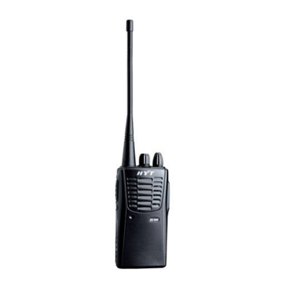
Product Controls Service Manual 2. Product Controls (4) Power (3) Channel (1) Antenna (2) LED Indicator On-Off/Volume Control Selector Knob Knob (5) PTT Key (6) MONI Key (7) Microphone (8) Speaker (9) Accessory Jack (10) Battery (11) Belt Clip (12) Battery Latch (13) Charging Piece *... - Page 6 Service Manual Product Controls Operation Description Short press Squelch Off SK1 Key Long press * Channel Selector Knob Rotate the knob to select your desired channel. * Power On-Off/Volume Control Knob Rotate the knob to turn the radio on/off or to adjust the volume. *...
- Page 7 Product Controls Service Manual Item Indication When the radio is turned on, a power-on alert tone sounds. Power On (to enter User Mode) When the radio is currently on a blank channel, it sounds beep tones continuously. The LED flashes red, and the low-pitched tone Low Battery Alert sounds every 20 seconds (programmable by the dealer).
-
Page 8: Software Specifications
Service Manual Software Specifications 3. Software Specifications Function List Channel Capacity: 1 – 16 Channel Spacing: 25KHz/12.5KHz* Channel Scan RX/TX status indication (red/green LED) CTCSS/CDCSS (38 groups of CTCSS, 83 groups of CDCSS, and CTCSS Tail Invert by 180 degrees.) Low battery alert Battery Save Unlock Detection and Emergency Alarm... - Page 9 Software Specifications Service Manual Scanning Squelch Off Squelch Off Momentary Power Adjustment Battery Strength Indicator Description of Modes 3.3.1 User Mode It is a conventional communication mode. The radio will enter this mode by default after power-on. 3.3.2 PC Programming Mode The radio in User Mode enters PC Programming Mode through specific protocol based communication with the programming software.
- Page 10 Service Manual Software Specifications During cloning, LED of the source radio solidly glows red, and LED of the target radio solidly glows green. When cloning is completed, LED of the source radio solidly glows green, and the green LED of the target radio goes out, which indicates the preparation for another clone. If any abnormal situation occurs during cloning, the source radio will stop cloning and its LED will flash orange, which indicates the preparation for another clone.
- Page 11 Software Specifications Service Manual To switch between wide and narrow bands Under a certain tuning item, long press the PTT key (the LED flashes orange to indicate valid press) to switch between wide and narrow bands. After the band is selected, the first frequency of the current band is the frequency for tuning by default.
-
Page 12: Circuit Description
Service Manual Circuit Description 4. Circuit Description General Principle Diagram The general circuit is composed of RDA chip circuit, TX circuit, RX circuit, power supply circuit, control circuit, etc. See the block diagram below: Figure 1 RDA Chip Circuit This chip is highly integrated. Its function includes voice signal processing/modulation/demodulation, DSP, VCO, PLL, LNA and RF IF. - Page 13 Circuit Description Service Manual The modulated RF signal from RDA chip goes to Q407 and Q402 for amplification, and then further amplified by Q403. Then the amplified signal is delivered to low-pass filter to filter out the high-order harmonics. Finally, it is sent via the antenna. RX Circuit After going through LPF and amplitude limiter, the RF signal received from the antenna enters Q501 LNA for amplification.
- Page 14 Service Manual Circuit Description given below: I ADC I PGA DSP Core Audio filter Switch 0/90 Sub CH filter FM Modem AFC loop Q ADC Q PGA PA_driver GPIO DVDD RSSI Interfac Syntheizer AVDD 3.3~ 4.8V XTAL After entering RDA chip via MIC, the voice signal will undergo A/D conversion to get digital signal, which will be delivered to DSP for further processing such as filtering, amplification, amplitude-limiting and pre-emphasizing.
- Page 15 Circuit Description Service Manual BIAS DOWN U401 Figure 3 The modulated RF signal from RDA chip goes to Q407 and Q402 for amplification, and then further amplified by Q403. Then the amplified signal is delivered to low-pass filter to filter out the high-order harmonics.
- Page 16 Service Manual Circuit Description ANT LPF D401 D402 RX_EN Q501 AT41511 BPF1 Figure 4 The RF signal is received via the antenna. After going through LPF and amplitude limiter, the signal is amplified by Q501 LNA. The LNA adopts 2SC3356 with current <5mA and its gain is about 12dB. Next, the BPF will remove the interference signal in amplified RF signal.
- Page 17 Circuit Description Service Manual EXT_PTT /EXT_MIC U622 MC9S08AC60 SDA/SCL CSS/CODE/INT/SDO /RXON/TXON/SQ/PDN Figure5 MCU Control Circuit MCU control circuit is composed of MCU, EEPROM, keys, etc. This section has the following functions: to initialize data of the radio and save data to EEPROM; to detect battery voltage and signals from external keys, LD and VOX, and to make response;...
- Page 18 Service Manual Circuit Description TX power supply; (for programming) to communicate with PC via RXD/TXD based on the RS232 protocol, and transmit/receive data to/from PC. RDA Chip Control By controlling the RDA chip, the MCU can realize these services: frequency setting, frequency bandwidth, reference clock, sleep mode, SQ, VOX, squelch, frequency deviation, voice filtering, signaling encoding/decoding, pre-emphasizing, gain control, amplitude limiting, de-emphasizing, etc.
-
Page 19: Cpu Pins
CPU Pins Service Manual 5. CPU Pins PIN No. Pin Name Definition Description PTC4 Reserved Reserved IRQ/TPMCLK Reserved Reserved RESET RESET Reset PTF0/TPM1CH2 BEEP Tone PTF1/TPM1CH3 VRCR PWM output for freq. adjustment PTF2/TPM1CH4 PWM output for PA APC Detection pin, CDCSS status PTF3/TPM1CH5 output PTF4/TPM2CH0... - Page 20 Service Manual CPU Pins PIN No. Pin Name Definition Description PTG0/KBI1P0 Detection pin, SQ status check PTG1/KBI1P1 TX_EN TX power supply control PTG2/KBI1P2 RX_EN RX power supply control PTA0 Rotary switch PTA1 Rotary switch PTA2 Rotary switch PTA3 Rotary switch PTA4 Reserved Reserved...
- Page 21 CPU Pins Service Manual PIN No. Pin Name Definition Description PTG3/KBI1P3 Reserved Reserved PTG4/KBI1P4 Reserved Reserved PTD4/TPM2CLK/AD1P12 BAT_DET Battery detection PTD5/AD1P13 Reserved Reserved PTD6/TPM1CLK/AD1P14 Reserved Reserved PTD7/KBI1P7/AD1P15 Reserved Reserved VREFH VREFH AD reference voltage VREFL VREFL AD reference grounding BKGD/MS BKGD Tuning communication PTG5/XTAL...
-
Page 22: Parts List 1
Service Manual Parts List 1 6. Parts List 1 Print Part No. Description Qty. R419 3099080398000 Chip resistor 0.39Ω J 1/4W 1206 (RoHS) R420 3099080398000 Chip resistor 0.39Ω J 1/4W 1206 (RoHS) R421 3099080398000 Chip resistor 0.39Ω J 1/4W 1206 (RoHS) L102 3001060000000 Chip resistor 0Ω... - Page 23 Parts List 1 Service Manual Print Part No. Description Qty. R646 3001051030000 Chip resistor 10KΩ J 1/16W 0402 (RoHS) R685 3001051030000 Chip resistor 10KΩ J 1/16W 0402 (RoHS) R686 3001051030000 Chip resistor 10KΩ J 1/16W 0402 (RoHS) R629 3001051060000 Chip resistor 10M J 1/16W 0402 (RoHS) R315 3001051000020 Chip resistor 10Ω...
- Page 24 Service Manual Parts List 1 Print Part No. Description Qty. R418 3001062710000 Chip resistor 270Ω J 1/10W 0603 (RoHS) R444 3001062710000 Chip resistor 270Ω J 1/10W 0603 (RoHS) R216 3001052730010 Chip resistor 27KΩ F 1/16W 0402 (RoHS) R409 3001053310000 Chip resistor 330Ω F 1/16 0402 (RoHS) R439 3001053330010 Chip resistor 33KΩ...
- Page 25 Parts List 1 Service Manual Print Part No. Description Qty. C615 3101051030020 Chip Capacitor 0.01UF K 25V X7R 0402 (RoHS) C630 3101051030020 Chip Capacitor 0.01UF K 25V X7R 0402 (RoHS) C649 3101051030020 Chip Capacitor 0.01UF K 25V X7R 0402 (RoHS) C664 3101051030020 Chip Capacitor 0.01UF K 25V X7R 0402 (RoHS)
- Page 26 Service Manual Parts List 1 Print Part No. Description Qty. C113 3101051020010 Chip Capacitor 1000PF K 50V X7R 0402 (RoHS) C120 3101051020010 Chip Capacitor 1000PF K 50V X7R 0402 (RoHS) C126 3101051020010 Chip Capacitor 1000PF K 50V X7R 0402 (RoHS) C216 3101051020010 Chip Capacitor 1000PF K 50V X7R 0402 (RoHS)
- Page 27 Parts List 1 Service Manual Print Part No. Description Qty. C631 3101062250000 Chip Capacitor 2.2UF K 10V X5R 0603 (RoHS) C431 3101062490000 Chip Capacitor 2.4PF B 50V C0G 0603 (RoHS) C526 3101052790060 Chip Capacitor 2.7PF B 50V COG HQ 0402 (RoHS) C425 3101062210000 Chip Capacitor 220PF J 50V COG 0603 (RoHS)
- Page 28 Service Manual Parts List 1 Print Part No. Description Qty. C440 3101054710010 Chip Capacitor 470PF K 50V X7R 0402 (RoHS) C442 3101054710010 Chip Capacitor 470PF K 50V X7R 0402 (RoHS) C443 3101054710010 Chip Capacitor 470PF K 50V X7R 0402 (RoHS) C444 3101054710010 Chip Capacitor 470PF K 50V X7R 0402 (RoHS)
- Page 29 Parts List 1 Service Manual Print Part No. Description Qty. C681 3101054710010 Chip Capacitor 470PF K 50V X7R 0402 (RoHS) C517 3101050500010 Chip Capacitor 5PF B 50V COG 0402 (RoHS) C520 3101050500010 Chip Capacitor 5PF B 50V COG 0402 (RoHS) C450 3101060500010 Chip Capacitor 5PF B 50V COG 0603 (RoHS)
- Page 30 Service Manual Parts List 1 Print Part No. Description Qty. Q404 3403999000000 Transistor PNP+NPN -50V/50V -100mA/100mA 80/80 (RoHS) Q502 3403999000000 Transistor PNP+NPN -50V/50V -100mA/100mA 80/80 (RoHS) Q407 3408002000000 NPN transistor 12V 100mA 120 1GHz SMD (RoHS) Q501 3408002000000 NPN transistor 12V 100mA 120 1GHz SMD (RoHS) Q201 3411001000000 PNP transistor 50V 150mA 70~700 SOT-523 (RoHS)
-
Page 31: Tuning Description
Tuning Description Service Manual 7. Tuning Description Required Test Instruments Radio communication test set (HP8921) 1 set 10V/3A regulated DC power supply 1 set Digital voltmeter 1 set Ammeter 1 set Preparations Place the board to be tested on the test fixture (please ensure good connection between each test point and the fixture), and connect the board to a power supply with DC voltage of 6.0V. - Page 32 Service Manual Tuning Description 7.3.3 Difference between Factory Clone Mode and Clone Mode Clone Mode: Only clone relevant data in user mode (such as frequencies). Tuning parameters like tuning frequency, tuning item and base band parameter will not be cloned. Factory Clone Mode: Clone all the data excluding serial No.
- Page 33 Tuning Description Service Manual Note: Y indicates frequencies available for tuning, and the rest are blank channels without tuning items. Baseband Design Description: Squelch On/Off: to set the threshold value for enabling/disabling the squelch function. Calibrate Wide/Narrow SQ Open/Close: to tune the squelch threshold to compensate the circuit difference.
- Page 34 Service Manual Tuning Description Skip RX/TX High/Low Pass: to configure the audio filter (0: not skip; 1: to skip one filter; 2: to skip the other filter; 3: to skip two filters). Pre-emphasis: to configure the pre-emphasis function. Skip CTCSS/CDCSS High/Low: to set whether to skip CTCSS/CDCSS filter. RX CTCSS/CDCSS High Pass Filter: to configure the parameters of CTCSS/CDCSS filter.
- Page 35 Tuning Description Service Manual Measurement Tuning Specifications Test Item Condition Comp- / Remarks Instrume- Test Point Method onent channel. Rotate the Press MONI Channel key to adjust Selector knob the value. UHF: to channel 2. Then save 2.0W±0.3W your change Short press PTT I≤1.1A and go to...
- Page 36 Service Manual Tuning Description Measurement Tuning Specifications Test Item Condition Comp- / Remarks Instrume- Test Point Method onent narrow band test. Short press PTT to switch the frequency under test. Rotate the Channel Selector knob to channel 5. Short press PTT to switch the frequency.
- Page 37 Tuning Description Service Manual Measurement Tuning Specifications Test Item Condition Comp- / Remarks Instrume- Test Point Method onent narrow band test. Rotate the Channel Selector knob to channel 7. Short press PTT to switch the frequency. High Following wideband test, long press PTT to perform narrow band...
- Page 38 Service Manual Tuning Description Measurement Tuning Specifications Test Item Condition Comp- / Remarks Instrume- Test Point Method onent Short press PTT <20~15K your change to switch the and go to frequency. another AF Genl channel. Lvl: Following 120mV wideband test, Narrow long press PTT 2.1KHz~...
- Page 39 Tuning Description Service Manual Measurement Tuning Item Condition Specifications Compo- Test Instrument Test Point Method / Remarks nent Press MONI Communication key to adjust Test Set Rotate the the value. Antenna SSG: -47dBm (W/N): Max. RX Press Channel Then save MOD: 1KHz 0.6~1W Audio...
- Page 40 Service Manual Tuning Description Wide Band Narrow Band Item Freq. Freq. Freq. Freq. Freq. Freq. Freq. Freq. Freq. Freq. Threshold Max. TX Audio Deviation Rx Item Section RX Low Voltage Threshold Max. RX Audio Power Note: The value is subject to that of the source radio.
-
Page 41: Troubleshooting Flow Chart
Troubleshooting Flow Chart Service Manual 8. Troubleshooting Flow Chart TX Circuit Start Low TX power No voice No TX TX LED fails Replace D604 Normal TX power Check TX power supply? supply Check voice path (MIC&D102) D604 glows red? TX VCO locked? Check TX VCO Replace D604 Check TX path... - Page 42 Service Manual Troubleshooting Flow Chart RX Circuit...
- Page 43 Troubleshooting Flow Chart Service Manual Start Normal power-up alert tone? Normal speaker? Replace it Check U601, Normal MCU U602, U604, VCC? and U606 Normal MCU Replace X601 X601? Check pin Other control pins connection or are normal? reburn the program MCU is OK...
-
Page 44: Disassembly And Assembly
Service Manual Disassembly and Assembly 9. Disassembly and Assembly Removing the Battery To remove the battery, power off the radio first, push the battery latch upwards, and then take out the battery from the battery slot. See Figure 1. Figure 1 Removing the Aluminum Chassis and PCB Kit Step 1 Unfasten the two screws at the bottom of the radio. - Page 45 Disassembly and Assembly Service Manual Step 5 Lift the bottom of the aluminum chassis, pull the aluminum chassis backwards and take it out. See Figure 3. Figure 3 The disassembled parts are shown below: Figure 4 Removing the PTT Key Push PTT key from outer side of the aluminum chassis.
- Page 46 Service Manual Disassembly and Assembly Figure 5 Assembling the PTT Key Step 1 Apply double-sided tape to the front case. Step 2 Install the PTT key into its place from the inner side of the chassis. See Figure 6. Figure 6 Assembling the Battery Place the battery into the battery slot until a click is heard, as shown below:...
- Page 47 Disassembly and Assembly Service Manual 图 7...
-
Page 48: Exploded View
Service Manual Exploded View 10. Exploded View... -
Page 49: Parts List 2
Parts List 2 Service Manual 11. Parts List 2 Part No. Description Qty. 7102507000000 Machine screw 7102004021030 Self-tapping screw 7102009001000 Machine screw 7102504000300 Machine screw 7102505000110 Machine screw 7102004020100 Self-tapping screw 7400077000000 MIC Net 6100030000020 PTT key 6000050100000 Front case 6201006000000 Inner lining for knob 6000158000040... - Page 50 Service Manual Parts List 2 Part No. Description Qty. 6300052000000 Aluminum chassis 4400100008000 SMA RF connector 6000051000030 Rear cover 7000139000000 Spring of latch 6000039000000 Battery latch 7400014010020 Waterproof PC sheet 6201022000000 Battery cathode piece 5205000000280 Socket 5205000000190 Socket 4210060000000 Lead 4210060000100 Lead 5002230000000...
- Page 51 Parts List 2 Service Manual Part No. Description Qty. 6201738000000 Battery anode and cathode piece 7500154000000 Sponge pad of battery...
-
Page 52: Packing Guide
Service Manual Packing Guide 12. Packing Guide Antenna Battery Strap Charge Belt Clip Radio Unit Power Cable Documentation Kit Package Box... -
Page 55: Level Diagram
24dBm 13dBm 2450m Vrms 7dBm 37.5dBm 90m Vrms Q407 AF AMP Q402 Q403 2SC3356 U302 RD01 RD07 120m Vrms 36dBm -123dBm DAC/ADC 37dBm ANT LPF -122dBm D401 D402 -121.5dBm U101 RDA1846 Q501 AT41511 -109dBm -113dBm... -
Page 56: Block Diagram
B201 SP_JACK PJ-D3027D MICJACK Q407 Q402 Q403 2SC3356 RD01 RD07 AF AMP U302 VOX_DET U613 D656 BATTERY G602 D602 BIAS DOWN EXT_PTT /EXT_MIC U401 D601 DAC/ADC U622 MC9S08AC60 ANT LPF D401 D402 E2ROM SDA/SCL U603 VRCR CSS/CODE/INT/SDO /RXON/TXON/SQ/PDN U101 RDA1846 RX_EN U621 V_BAT... -
Page 57: Schematic Diagram
R633 R632 R632 C672 C672 U613 U613 C670 C670 C671 C671 0.1u 0.1u R636 R636 NJM2904 NJM2904 1000P 1000P 0.1u 0.1u HYT Science&technology Co.Ltd. R638 R638 Model Name: Page: R637 R637 Date: Part Name: Part Name: Rev: File No.: Prepare:... - Page 58 HD3P5X2P2 HD3P5X2P2 HD3P5X2P2 HD3P5X2P2 HD3P5X2P2 HD3P5X2P2 HD3P5X2P2 HD3P5X2P2 HD3P5X2P2 HD3P5X2P2 HD3X2P2 HD3X2P2 4.7k 4.7k HYT Science&technology Co.Ltd. HYT Science&technology Co.Ltd. HYT Science&technology Co.Ltd. Model Name: Model Name: Model Name: TC-500 TC-500 TC-500 Page: Page: Page: Part Name: Part Name: Part Name:...
- Page 59 2SC3356 2SC3356 C511 C511 C512 C512 HSM88AS HSM88AS R511 R511 2.2nH 2.2nH C518 C518 HYT Science&technology Co.Ltd. HYT Science&technology Co.Ltd. HYT Science&technology Co.Ltd. Model Name: Model Name: Model Name: TC-500 TC-500 TC-500 Page: Page: Page: Part Name: Part Name: Part Name:...
-
Page 60: Specifications
Service Manual Specifications 17. Specifications General Frequency Range 400 – 470MHz Channel Capacity Channel Spacing 25 KHz /12.5KHz Operating Voltage 6.0V DC Battery 1100mAh (Ni-MH Battery) Battery Life (5-5-90 Duty Cycle) ≥7 hours Operating Temperature -20℃ – +60℃ Dimensions (H×W×D) 109×54×34mm (with standard... - Page 61 Specifications Service Manual Spurious and Harmonics ≤-26dBm Modulation Limiting ≤5KHz/2.5KHz FM Noise ≥40dB/35dB Modulation Distortion ≤5% Adjacent Channel Power ≤-70dB/-60dB Note: All Specifications are tested according to TIA/EIA-603, and subject to change without notice due to continuous development. We endeavor to achieve the accuracy and completeness of this manual, but no warranty of accuracy or reliability is given.
- Page 62 9 06...
Need help?
Do you have a question about the TC-500 and is the answer not in the manual?
Questions and answers