Table of Contents
Advertisement
Contents
General.....................................................................................................................................................1
Radio Overview ........................................................................................................................................2
Software Specifications ............................................................................................................................5
Circuit Description ....................................................................................................................................6
CPU Pins................................................................................................................................................13
TC-780 VHF Parts List 1 (Main Board Unit) ...........................................................................................18
TC-780 UHF Parts List 1 (Main Board Unit) ...........................................................................................18
TC-780 VHF/UHF Parts List 1 (Keyboard Unit) ......................................................................................18
Adjustment Description...........................................................................................................................18
Troubleshooting Flow Chart ...................................................................................................................27
Disassembly and Assembly for Repair ...................................................................................................32
Exploded View........................................................................................................................................36
TC-780 Parts List 2.................................................................................................................................37
Packing...................................................................................................................................................39
TC-780 VHF PCB View ..........................................................................................................................41
TC-780 UHF PCB View ..........................................................................................................................41
TC-780 VHF/UHF PCB View..................................................................................................................41
TC-780 Block Diagram ...........................................................................................................................41
TC-780 VHF Schematic Diagram ...........................................................................................................41
TC-780 UHF Schematic Diagram...........................................................................................................41
TC-780 VHF/UHF Schematic Diagram...................................................................................................41
Specifications .........................................................................................................................................42
Advertisement
Table of Contents

Related Manuals for HYT TC-780


Summary of Contents for HYT TC-780
-
Page 1: Table Of Contents
Radio Overview ............................2 Software Specifications ..........................5 Circuit Description ............................6 CPU Pins..............................13 TC-780 VHF Parts List 1 (Main Board Unit) ...................18 TC-780 UHF Parts List 1 (Main Board Unit) ...................18 TC-780 VHF/UHF Parts List 1 (Keyboard Unit) ..................18 Adjustment Description...........................18 Troubleshooting Flow Chart ........................27 Disassembly and Assembly for Repair ....................32... -
Page 2: General
This equipment should be serviced by qualified technicians only. Use only HYT supplied or approved antenna. Turn off your radio prior to entering any area with a potentially explosive atmosphere. To avoid electromagnetic interference and/or compatibility conflicts, turn off your radio in any facility where posted notices instruct you to do so. -
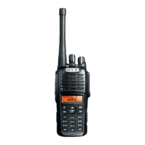
Page 3: Radio Overview
TC-780 Service Manual Radio Overview ○ ○ ○ ○ 1 PTT (Push-to-Talk) Key 2 SK1 (Side Key 1) 3 SK2 (Side Key 2) 4 Antenna ○ ○ ○ ○ 5 Microphone 6 Speaker 7 LCD Display 8 Function Keypad ○... - Page 4 TC-780 Service Manual Programmable function key. ﹡SK2 (Side Key 2) Programmable function key. ﹡LCD Display Used to display radio status information. ﹡Function Keypad Exit key Use the Exit key to return to the previous menu. Up key Down key Menu/Select key Used to enter the menu mode.
- Page 5 TC-780 Service Manual Programmable function key. ﹡Channel Selector Knob Rotate the knob to select a desired channel. ﹡Radio On-Off/Volume Control Knob Rotate the knob clockwise to turn the radio on, and rotate the knob fully counter-clockwise until a click is heard to turn the radio off.
-
Page 6: Software Specifications
TC-780 Service Manual Software Specifications Specifications 256 Conventional Channels 32 Channel Groups 2-Tone/DTMF/HDC1200/HDC2400 Encode & Decode ATIS Encode Priority Channel Scan When the radio operates in talkaround mode, the channel scan feature provides users with an easy way to monitor and join other channels. -
Page 7: Circuit Description
TC-780 Service Manual External Scrambler Patrol Record GPS Function Description 1. User Mode This mode is for normal operation by end users. 2. All Reset Mode Allows you to initialize tuning items, channel frequency, and conventional functions. See the Adjustment Description section for details. - Page 8 TC-780 Service Manual circuit, power supply circuit, and MCU control circuit. Frequency Configuration The receiver section utilizes double conversion. The first IF is 44.85MHz and the second IF is 455 KHz. The first local oscillator signal is supplied by PLL and VCO circuit. The second local oscillator signal is generated from TCXO (44.395MHz);...
- Page 9 TC-780 Service Manual second local oscillator signal (44.395MHz) again to create a 455 KHz second IF signal, which passes through a ceramic filter (wide band: Z404; narrowband: Z403) to eliminate unwanted signals. The resulting signal is detected by U403 to output audio signal from Pin 9.
- Page 10 TC-780 Service Manual MIC Circuit and Modulation Circuit The audio signal from microphone is amplified by U204 after passing through the MIC control switch (Q616). The resulting signal is then amplified, pre-emphasized and etc by U203. Simultaneously, DTMF/2-Tone/5-Tone signallings generated by the MCU are amplified by U203, and then mixed with MIC audio signal, and finally fed to VCO for modulation.
- Page 11 TC-780 Service Manual Figure 3 PLL Circuit Control Circuit The control circuit is comprised of MCU control circuit and power supply controller. U605 (MCU) operates at 9.8304 MHz. The CPU controls data transmission among receive circuit, transmit circuit, control circuit, display circuit and peripheral circuit.
- Page 12 TC-780 Service Manual Power Supply Power supply of the radio is derived from the battery that supplies battery B+ after passing through fuse, and then passes through power switch. MCU controls power management IC (U602, U603, and U604) to generate voltage including C5V, 5CNS, R5V, T5V.
- Page 13 TC-780 Service Manual Figure 6 Display Circuit...
-
Page 14: Cpu Pins
TC-780 Service Manual CPU Pins Port Name Pin Name Function Remarks Automatic power control/Rx bandpass control. Adjust APC and Rx bandpass P94/DA1 APC/TV through DA (0-5V). DTMF/2-Tone/5-Tone/Beep output /ALARM output generates waveform). P93/DA0 TONEO Cannot output from speaker. LCM data, display module control LCM_SDI data pin. - Page 15 TC-780 Service Manual VCO for modulation. GPS_In GPS input (PWM) output CTCSS/CDCSS to P74/TA2O CTC_PLL PLL for modulation. Programmable port used for future Used for future AUX2 development. development. P72/TA1O Accessory Port P71/RxD2/TB5IN (patrol record) Accessory Port P70/TxD2 (patrol record)
- Page 16 TC-780 Service Manual AK2346 DATA I/O(SDAT). Output control word or read data., P47/CS3 AF_DIO Control power supply. H: supply power; L: soft power P46/CS2 down. Battery save control. P45/CS1 SAVE H: valid; L: battery save. R5C Control power of receiver.
- Page 17 TC-780 Service Manual Control PLL pump current to improve phase lock speed. P17/INT5 PUMP_SW H: high current; L: low current. Rise edge is generated when the P16/INT4 DTMF_EST decode chip detects DTMF data. P15/INT3 MANDOWN Man down detect. Audio path switch.
- Page 18 TC-780 Service Manual P105/AN5 MIC signal input P104/AN4 BATT BATT Battery level detect. Battery identification. P103/AN3 BATTSEL Identify battery chemistry. P102/AN2 RSSI RSSI detect pin. P101/AN1 Squelch level input. A/D conversion power grounded AVSS input. P100/AN0 CTC_IN CTCSS signal input.
-
Page 19: Tc-780 Vhf Parts List 1 (Main Board Unit)
TC-780 Service Manual TC-780 VHF Parts List 1 (Main Board Unit) TC-780 UHF Parts List 1 (Main Board Unit) TC-780 VHF/UHF Parts List 1 (Keyboard Unit) Adjustment Description Required Test Instruments Radio communication test set 1 set Scanner 1 set... - Page 20 TC-780 Service Manual “Reset function” “Reset radioINFO” “Reset all data” Press to select a reset type. Press to return to the previous menu, or to confirm and enter the lower level menu. When confirming initiation data, the LCD displays as follows according to the three reset types: "Confirm ?"...
- Page 21 TC-780 Service Manual The purpose of manual adjustment is to adjust Tx frequency deviation, transmit power, Rx sensitivity, squelch, and etc. 1) SK2 Key Set the operating frequency. Center frequency F3 is for one-point adjustment; F1, F3 and F5 are for three-point adjustment, and F1 through F5 are for five-point adjustment.
- Page 22 TC-780 Service Manual RX: {RX3}. 7) Frequency Table of Five-point Adjustment Frequency Band Point 1 (MHz) Point 2 (MHz) Point 3 (MHz) Point 4 (MHz) Point 5 (MHz) (MHz) 136-174(V) TX1:136 TX2:145.5 TX3:155 TX4:164.5 TX5:174 RX1:136.15 RX2:145.65 RX3:155.15 RX4:164.65 RX5:173.85...
- Page 23 TC-780 Service Manual Power in tuning Enter the adjustment Radio PTT (up) Adjust power to mode (Power In mode and select an item. Communication SK1 (down) 300±200mW tune) The radio transmits. Test Set Adjust point 5 of wide TX TEST the Channel band.
- Page 24 TC-780 Service Manual CTCSS Enter the adjustment PTT (up) Adjust frequency (254.1Hz) mode and select an item. SK1 (down) deviation to 750Hz, High Frequency Adjust point 3 of wide 600Hz, 400Hz for wide, Deviation band, point 1 of medium the Channel...
- Page 25 TC-780 Service Manual VOX GAIN1 Enter the adjustment Save Adjust the frequency to (bVox Gain Min) mode and select an item. 1KHz, and amplitude to Adjust point 1 of wide 10mv for modulation band. Radio signal, and then press Communication the PTT to save.
- Page 26 TC-780 Service Manual Bandpass Waveform Enter the adjustment PTT (up) Adjust the bandpas mode and select the Rx Scanner SK1 (down) waveform to: Sensitivity item. Adjust Bandpass Test point 5 of wide band. Fixture Channel Selector knob (1-255) UHF: VHF:...
- Page 27 TC-780 Service Manual SQL Value of Normal Enter the adjustment Radio Save Adjust the level Squelch Open mode and select an Communication to -120dBm and (SqlNorOpen) item. Adjust point 5 of Test Cable press PTT to wide band, point 1 of Audio Test save.
-
Page 28: Troubleshooting Flow Chart
TC-780 Service Manual Troubleshooting Flow Chart... - Page 29 TC-780 Service Manual MCU Check Check the Normal power-on The RF circuit can’t alert tone? be driven. control circuit Speaker works well? Replace the speaker 9.8304 MHz Read and write Reset works normally? available? Check reading & writing circuit Q610 works...
- Page 30 TC-780 Service Manual VCO Check Power supply is Replace Q306 normal? Oscillator Check Replace CV voltage in Rx is if Q102 works Q102 normal? well. Check if Q105 outputs Check Q105 normally? Check if feedback is Check Q107 normal. Check Check power if 16.8MHz...
- Page 31 TC-780 Service Manual No output power Power supply Check power works well? supply circuit The current is Control voltage is Check Q607 normal? normal? High Check transistor, Check drive offset voltage & stage low pass network Repair the Drive stage is...
- Page 32 TC-780 Service Manual No receive Power Control Supply of audio IC voltage PA_MUTE Replace Q615 is normal? is normal? Replace U609 Baseband Baseband IC Replace IC outputs inputs normally? AK2346 normally? U403 outputs Check U201 normally? Check volume switch and AF...
-
Page 33: Disassembly And Assembly For Repair
TC-780 Service Manual Disassembly and Assembly for Repair Disassemble the Radio Case 1. Remove the Radio On-Off/Volume Control knob ① and Channel Selector knob ②. 2. Lift the chassis by its bottom and pull it out of the radio case ③. - Page 34 TC-780 Service Manual Figure 2 Disassemble the Transmit and Receive Units 1. Screw out the waterproof ring ⑧, the nut ⑨, and screws ⑩ locking the keypad PCB, shown in figure 3. Figure 3...
- Page 35 TC-780 Service Manual ○ ○ ○ 2. Rotate the keypad PCB module 11 for 180 degrees, and then remove FPC 12 and FFC 13 from the connector on the PCB. Figure 4 ○ ○ ○ 3. Remove the five DB head screws...
- Page 36 TC-780 Service Manual Figure 5 Precautions for Assembly Assemble the Radio Case and Chassis 1. Make sure the waterproof cushion surrounding the chassis is well fitted into the slot ① of the chassis. 2. Correctly position and assemble the speaker on the radio case ②.
-
Page 37: Exploded View
TC-780 Service Manual Figure 6 Exploded View... -
Page 38: Tc-780 Parts List 2
TC-780 Service Manual TC-780 Parts List 2 Material No. Description Qty. 6000135000000 PTT key cover (RoHS) - Page 39 TC-780 Service Manual 6100068000000 PTT key (silica rubber) (RoHS) 6100319000000 Emergency key (silica rubber) (RoHS) 7500210000000 Adhesive tape, light guide 3M(9448) (RoHS) 6000609000000 Light guide (RoHS) 7400208000000 Felt, speaker PES+PBO(U500PBO) ¢40.0 (RoHS) 5001210000170 Speaker 20Ω 1W/3W 90dB Φ40mm H5.0mm (RoHS)
-
Page 40: Packing
TC-780 Service Manual Packing... - Page 41 TC-780 Service Manual...
-
Page 42: Tc-780 Vhf Pcb View
TC-780 Service Manual TC-780 VHF PCB View TC-780 UHF PCB View TC-780 VHF/UHF PCB View TC-780 Block Diagram TC-780 VHF Schematic Diagram TC-780 UHF Schematic Diagram TC-780 VHF/UHF Schematic Diagram... -
Page 43: Specifications
TC-780 Service Manual Specifications General VHF: 136-174MHz Frequency Range UHF: 350-390MHz 400-470MHz 450-520MHz Channel Capacity Channel Spacing 25/20/12.5KHz Operating Voltage 7.4V Battery 1700mAh (Li-Ion) Battery Life (5-5-90 duty cycle) About 14 hours Operating Temperature -25℃-+60℃ Dimensions (H×W×D) 124×54×35mm (with battery, without antenna) Weight (with antenna &... - Page 44 TC-780 Service Manual HYT endeavors to achieve the accuracy and completeness of this manual, but no warranty of accuracy or reliability is given. All the specifications and design are subject to change without prior notice due to continuous technology development. Changes which may occur after publication are highlighted by Revision History contained in Service Manual.
Need help?
Do you have a question about the TC-780 and is the answer not in the manual?
Questions and answers