Table of Contents
Advertisement
Quick Links
Advertisement
Table of Contents

Related Manuals for HYT TC-700 Ex PLUS


Summary of Contents for HYT TC-700 Ex PLUS
- Page 1 INTRINSICALLY SAFE 813700EX00100 2007-01-20...
-
Page 2: Table Of Contents
TC-700 Ex PLUS Level Diagram------------------------------------------------------------------------68 TC-700 Ex PLUS Block Diagram-----------------------------------------------------------------------69 TC-700 Ex PLUS VHF Schematic Diagram(RF) ---------------------------------------------------70 TC-700 Ex PLUS VHF Schematic Diagram (Baseband & AF Amplifier)----------------------71 TC-700 Ex PLUS UHF Schematic Diagram(RF) ---------------------------------------------------72 TC-700 Ex PLUS UHF Schematic Diagram (Baseband & AF Amplifier)----------------------73... -
Page 3: General
It contains all service information required for the equipment and is current as of the publication date. HYT endeavors to achieve the accuracy and completeness of this manual, but no warranty of accuracy or reliability is given. All the specifications and design are subject to change without prior notice due to continuous technology development. -
Page 4: Atex-Approved Intrinsically Safe Radio Information
It replaces the Cenelec classification in all European Union member states and EFTA countries. All HYT professional series ATEX portable radios are approved to ATEX Protection Classes II 2 G EEx ib IIB T3 and II 2D IP64 T160° C as interpreted in the following... -
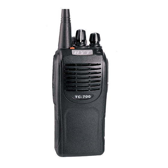
Page 5: Radio Overview
TC-700 Ex PLUS Service Manual Radio Overview PTT (Push-to-Talk) Key Press and hold down the PTT key to transmit, release it to receive. SK1 (Side Key 1) (programmable) SK2 (Side Key 2) (programmable) Antenna Microphone Speaker TK (Top Key) (programmable) Channel Selector Knob Rotate the knob to select from channel 1 to 16. - Page 6 TC-700 Ex PLUS Service Manual Wired Cloning Source radio: Turn the source radio on while The orange LED flashes twice. holding down the PTT and SK2. Slave radio: Rotate the On-Off/Volume Control knob clockwise to turn the slave radio on.
-
Page 7: Software Specifications
TC-700 Ex PLUS Service Manual Decoding (2-Tone (5-Tone)/HDC1200/HDC2400TM) Orange LED flashes after the signalling is successfully decoded. Select Power Level 0.5W: One beep is heard; 1.5W: Two beeps are heard; 3W: Three beeps are heard. Function Key Press One beep to enable, two beeps to disable. - Page 8 TC-700 Ex PLUS Service Manual All Reset is completed). Frequency settings are shown as follows: Selected Channel F1 (MHz) F2 (MHz) F3 (MHz) F4 (MHz) F5 (MHz) Frequency Band(MHz) TX1:136 TX2:145.5 TX3:155 TX4:164.5 TX5:174 136 - 174 (V) RX1:136.1 RX2:145.6 RX3:155.1...
- Page 9 TC-700 Ex PLUS Service Manual Wireless Cloning Mode Select wireless cloning from optional functions in programming software, turn the radio on while holding down PTT and SK1 key simultaneously for 2 seconds, then the source and slave radios enter wireless cloning mode with orange LED flashing once (when both radios are turned on and stay in the same channel), hold down PTT on the source radio to begin cloning.
- Page 10 TC-700 Ex PLUS Service Manual (7) Frequency Setting 5 point tuning (MHz) TX: { TX1,TX2,TX3,TX4,TX5 RX: { RX1,RX2,RX3,RX4,RX5 3 point tuning (MHz) TX: { TX1, TX3, TX5 RX: { RX1, RX3, RX5 1 point tuning (MHz) TX: { RX: { First Group of Adjustment Items Channel No.
-
Page 11: Circuit Description
TC-700 Ex PLUS Service Manual Circuit Description Power Supply The radio power is supplied by the battery. The power supply is from B+, and supplies power SWB+ for the three AVRs, after passing through fuse FE250mA and switch. IC504 supplies 5V (M5V) voltage for the control circuit. - Page 12 TC-700 Ex PLUS Service Manual PLL Circuit Step frequency of PLL can be 2.5 KHz, 5.0 KHz or 6.25 KHz. A 16.8MHz reference oscillator signal is divided at IC301 by a counter to generate a 2.5 KHz, 5.0 KHz or 6.25 KHz reference frequency. Output signal from VCO is buffer amplified by Q301 and divided at IC301 by a frequency divider.
- Page 13 TC-700 Ex PLUS Service Manual 450KHz ceramic filter (wide: CF201,narrow: CF202) to eliminate unwanted signals before it is amplified and detected in IC204. Narrow/Wide Switch Circuit Pin WCON and pin NCON of IC500 outputs wide (high level) and narrow (low level) channel spacing signal respectively to turn on corresponding diode-connector, and to choose ceramic filter CF201 (wide) or CF202 (narrow) to filter useless spurious signal.
- Page 14 TC-700 Ex PLUS Service Manual The automatic power control (APC) circuit stabilizes the transmit power by detecting the drain current of final stage amplifier FET. IC101 (2/2) compares the preset reference voltage with the voltage obtained from final current. APC voltage is in proportion to the difference between auto detect voltage and reference voltage output from IC101 (1/2).
- Page 15 TC-700 Ex PLUS Service Manual etc., after being amplified. And then it enters AF PA driven speaker. Baseband processed chip provides functions for processing signal as amplifying, filtering, emphasizing, scrambling, companding, and amplitude limiting. Control System The IC500 CPU operates at 9.8304 MHz.
-
Page 16: Cpu Pins
TC-700 Ex PLUS Service Manual CPU Pins MCU Port Port Name Input/Output Features P94/DA1 APC/TV Automatic Power Control P93/DA0 TONEO DTMF/2-Tone (5-Tone)/Beep tone output/ ALARM tone output P92/TB2IN SHIFT Clock beat-frequency BYTE BYTE CNVSS CNVSS P87/XCIN P86/XCOUT 10 RESET RESET... - Page 17 TC-700 Ex PLUS Service Manual MCU Port Port Name Input/Output Features 36 P60 COM2 37 P57/RDY EEDAT EEPROM DATA, date input/output. 38 P56/ALE EECLK EEPROM CLK 39 P55/HOLD 40 P54/HLDA AFDIR AK2346 DIR 41 P53/BLCK AFSCK 2346 SCLK 42 P52/RD...
- Page 18 TC-700 Ex PLUS Service Manual MCU Port Port Name Input/Output Features 73 P15/INT3 74 P14 ALARM 75 P13 DC-Switch 76 P12 PLL_UL PLL unlock detect 77 P11 PLL_STB PLL strobe output 78 P10 MICMUTE MICMUTE 79 P07/D7 Option1 Programming cable detect.
-
Page 19: Parts List 1
TC-700 Ex PLUS Service Manual Parts List 1 TC-700 Ex PLUS VHF Parts List 1 Material No. Description Qty. Ref No. Print No. 3001050000000 Chip resistor 0402 0Ω J 1/16W R147 3001050000000 Chip resistor 0402 0Ω J 1/16W R254 3001050000000 Chip resistor 0402 0Ω J 1/16W R303 3001050000000 Chip resistor 0402 0Ω... - Page 20 TC-700 Ex PLUS Service Manual Material No. Description Qty. Ref No. Print No. 3001051020010 Chip resistor 0402 1KΩ J 1/16 R551 3001051020010 Chip resistor 0402 1KΩ J 1/16 R553 3001051020010 Chip resistor 0402 1KΩ J 1/16 R555 3001051020010 Chip resistor 0402 1KΩ J 1/16 R560 3001051020010 Chip resistor 0402 1KΩ...
- Page 21 TC-700 Ex PLUS Service Manual Material No. Description Qty. Ref No. Print No. 3001051040010 Chip resistor 0402 100KΩ J 1/ R493 3001051040010 Chip resistor 0402 100KΩ J 1/ R516 3001051040010 Chip resistor 0402 100KΩ J 1/ R557 3001051040010 Chip resistor 0402 100KΩ J 1/ R559 3001051050020 Chip resistor 0402 1MΩ...
- Page 22 TC-700 Ex PLUS Service Manual Material No. Description Qty. Ref No. Print No. 3001052230010 Chip resistor 0402 22KΩ J 1/1 R494 3001052240000 Chip resistor 0402 220KΩ J 1/ R302 3001052240000 Chip resistor 0402 220KΩ J 1/ R345 3001052240000 Chip resistor 0402 220KΩ J 1/ R439 3001052240000 Chip resistor 0402 220KΩ...
- Page 23 TC-700 Ex PLUS Service Manual Material No. Description Qty. Ref No. Print No. 3001054730000 Chip resistor 0402 47KΩ J 1/1 R506 3001054730000 Chip resistor 0402 47KΩ J 1/1 R507 3001054730000 Chip resistor 0402 47KΩ J 1/1 R515 3001054730000 Chip resistor 0402 47KΩ J 1/1 R535 3001054730000 Chip resistor 0402 47KΩ...
- Page 24 TC-700 Ex PLUS Service Manual Material No. Description Qty. Ref No. Print No. 3005051020010 Resistor array 0402 1K*4 J 1/16 CP526 3101050400010 Chip capacitor 0402 4PF B 50V C202 3101050400010 Chip capacitor 0402 4PF B 50V C233 3101050400010 Chip capacitor 0402 4PF B 50V...
- Page 25 TC-700 Ex PLUS Service Manual Material No. Description Qty. Ref No. Print No. 3101051020010 Chip capacitor 0402 1000PF K 5 C546 3101051020010 Chip capacitor 0402 1000PF K 5 C558 3101051030020 Chip capacitor 0402 0.01UF K 2 C121 3101051030020 Chip capacitor 0402 0.01UF K 2 C147 3101051030020 Chip capacitor 0402 0.01UF K 2...
- Page 26 TC-700 Ex PLUS Service Manual Material No. Description Qty. Ref No. Print No. 3101052200010 Chip capacitor 0402 22PF J 50V C471 3101052200010 Chip capacitor 0402 22PF J 50V C472 3101052210010 Chip capacitor 0402 220PF K 50 C211 3101052210010 Chip capacitor 0402 220PF K 50...
- Page 27 TC-700 Ex PLUS Service Manual Material No. Description Qty. Ref No. Print No. 3101054710010 Chip capacitor 0402 470PF K 50 C610 3101054720000 Chip capacitor 0402 4700PF K 5 C485 3101054730000 Chip capacitor 0402 0.047UF K C427 3101054740000 Chip capacitor 0402 0.47UF Z 6 C475 3101054740000 Chip capacitor 0402 0.47UF Z 6...
- Page 28 TC-700 Ex PLUS Service Manual Material No. Description Qty. Ref No. Print No. 3102992000040 Trimmer capacitor 3.2*2.5*1.25mm TC301 3102992000040 Trimmer capacitor 3.2*2.5*1.25mm TC302 3104072250010 Tantalum capacitor 0805 2.2UF M 10V C327 3104072260010 Tantalum capacitor 0805 22UF M 6.3V C470 3210108330000 Bobbin inductor 1206 33nH...
- Page 29 TC-700 Ex PLUS Service Manual Material No. Description Qty. Ref No. Print No. 3231351640000 Air-core inductor E2-0.35*1.6*4TL L112 3231351660000 Air-core inductor E2-0.35*1.6*6TR L114 3231351660000 Air-core inductor E2-0.35*1.6*6TR L119 3231351670000 Air-core inductor E2-0.35*1.6*7TR L113 3231351680000 Air-core inductor E2-0.35*1.6*8TR L109 3231351680000 Air-core inductor E2-0.35*1.6*8TR...
- Page 30 TC-700 Ex PLUS Service Manual Material No. Description Qty. Ref No. Print No. 3403003000060 Transistor 2SC4617TLS Q306 3403007000000 Transistor DTA114EE(TL) Q205 3403007000000 Transistor DTA114EE(TL) Q406 3403007000070 Transistor DTA144EE Q110 3403007000070 Transistor DTA144EE Q201 3403008000010 Transistor DTC114EE(TL) Q108 3403008000010 Transistor DTC114EE(TL)
- Page 31 TC-700 Ex PLUS Service Manual Material No. Description Qty. Ref No. Print No. 3104071060010 Tantalum capacitor 0805 10UF M 6.3V C316 3104071060010 Tantalum capacitor 0805 10UF M 6.3V C342 3104071060010 Tantalum capacitor 0805 10UF M 6.3V C412 3104071060010 Tantalum capacitor 0805 10UF M 6.3V C418 3104071060010 Tantalum capacitor 0805 10UF M 6.3V...
- Page 32 TC-700 Ex PLUS Service Manual Material No. Description Qty. Ref No. Print No. 3101051050000 Chip capacitor 0402 1UF K 6.3V C491 3101051050000 Chip capacitor 0402 1UF K 6.3V C495 3101051050000 Chip capacitor 0402 1UF K 6.3V C496 3101051050000 Chip capacitor 0402 1UF K 6.3V C525 3101051050000 Chip capacitor 0402 1UF K 6.3V...
- Page 33 TC-700 Ex PLUS Service Manual Material No. Description Qty. Ref No. Print No. 3001061020010 Chip resistor 0603 1KΩ J 1/10 3001061020010 Chip resistor 0603 1KΩ J 1/10 3001061020010 Chip resistor 0603 1KΩ J 1/10 3001061020010 Chip resistor 0603 1KΩ J 1/10 3001082010000 Chip resistor 1206 200Ω...
- Page 34 TC-700 Ex PLUS Service Manual TC-700 Ex PLUS UHF Parts List 1 Material No. Description Qty. Ref. No. Print No. 3001050000000 Chip resistor 0402 0Ω J 1/16W C488 3001050000000 Chip resistor 0402 0Ω J 1/16W L201 3001050000000 L202 Chip resistor 0402 0Ω J 1/16W...
- Page 35 TC-700 Ex PLUS Service Manual Material No. Description Qty. Ref. No. Print No. 3001051020010 Chip resistor 0402 1KΩ J 1/16 R555 3001051020010 Chip resistor 0402 1KΩ J 1/16 R560 3001051020010 R563 Chip resistor 0402 1KΩ J 1/16 3001051020010 R565 Chip resistor 0402 1KΩ J 1/16...
- Page 36 TC-700 Ex PLUS Service Manual Material No. Description Qty. Ref. No. Print No. 3001051230000 Chip resistor 0402 12KΩ J 1/1 R238 3001051240000 Chip resistor 0402 120KΩ J 1/ R339 3001051510000 R304 Chip resistor 0402 150Ω J 1/1 3001051520000 R106 Chip resistor 0402 1.5KΩ J 1/...
- Page 37 TC-700 Ex PLUS Service Manual Material No. Description Qty. Ref. No. Print No. 3001052710010 Chip resistor 0402 270Ω J 1/1 R230 3001052710010 Chip resistor 0402 270Ω J 1/1 R232 3001052710010 R316 Chip resistor 0402 270Ω J 1/1 3001052720000 R112 Chip resistor 0402 2.7KΩ J 1/...
- Page 38 TC-700 Ex PLUS Service Manual Material No. Description Qty. Ref. No. Print No. 3001054730000 Chip resistor 0402 47KΩ J 1/1 R515 3001054730000 Chip resistor 0402 47KΩ J 1/1 R535 3001054730000 R536 Chip resistor 0402 47KΩ J 1/1 3001054730000 R538 Chip resistor 0402 47KΩ J 1/1...
- Page 39 TC-700 Ex PLUS Service Manual Material No. Description Qty. Ref. No. Print No. 3101050500010 Chip capacitor 0402 5PF B 50V C268* 3101050500010 Chip capacitor 0402 5PF B 50V C360 3101050500010 Chip capacitor 0402 5PF B 50V C361 3101050600010 Chip capacitor 0402 6PF B 50V...
- Page 40 TC-700 Ex PLUS Service Manual Material No. Description Qty. Ref. No. Print No. 3101051030020 Chip capacitor 0402 0.01UF K 2 C461 3101051030020 Chip capacitor 0402 0.01UF K 2 C465 3101051030020 Chip capacitor 0402 0.01UF K 2 C486 3101051030020 Chip capacitor 0402 0.01UF K 2...
- Page 41 TC-700 Ex PLUS Service Manual Material No. Description Qty. Ref. No. Print No. 3101054710010 Chip capacitor 0402 470PF K 50 C149 3101054710010 Chip capacitor 0402 470PF K 50 C153 3101054710010 Chip capacitor 0402 470PF K 50 C154 3101054710010 Chip capacitor 0402 470PF K 50...
- Page 42 TC-700 Ex PLUS Service Manual Material No. Description Qty. Ref. No. Print No. 3101060500010 Chip capacitor 0603 5PF B 50V C310* 3101060500010 Chip capacitor 0603 5PF B 50V C320 3101060590010 Chip capacitor 0603 0.5PF B 50 C307 3101060590010 Chip capacitor 0603 0.5PF B 50...
- Page 43 TC-700 Ex PLUS Service Manual Material No. Description Qty. Ref. No. Print No. 3104074750030 Tantalum capacitor 0805 4.7UF M 10V C344 3104074750030 Tantalum capacitor 0805 4.7UF M 10V C452 3104074750030 Tantalum capacitor 0805 4.7UF M 10V C464 3104074750030 Tantalum capacitor 0805 4.7UF M 10V...
- Page 44 TC-700 Ex PLUS Service Manual Material No. Description Qty. Ref. No. Print No. 3214307181000 Inductor 0805 180nH(Q) C20 L209 3214307220010 Inductor 0805 22nH C2012C- L208* 3214307220010 Inductor 0805 22nH C2012C- L210* 3210306221000 Multi-layer inductor 0603 220nH L502 3210306221000 Multi-layer inductor 0603 220nH...
- Page 45 TC-700 Ex PLUS Service Manual Material No. Description Qty. Ref. No. Print No. 3401002000290 Transistor 2SC4116-GR Q401 3303030100010 Switching diode DAN222(TL) D202 3303030100010 Switching diode DAN222(TL) D203 3399990000260 Diode HSM88ASTL-E D208 3401002000990 Transistor 2SC5108-Y Q101 3401002000990 Transistor 2SC5108-Y Q111 3401002000990...
- Page 46 TC-700 Ex PLUS Service Manual Material No. Description Qty. Ref. No. Print No. 3605002057290 Operational amplifier TC75W51FU IC402 3605002057290 Operational amplifier TC75W51FU IC404 3605002057290 Operational amplifier TC75W51FU IC405 3605002057290 Operational amplifier TC75W51FU IC407 3499000000140 Transistor 2SK508-K52-T1B-A Q302 3499000000140 Transistor 2SK508-K52-T1B-A...
- Page 47 TC-700 Ex PLUS Service Manual Material No. Description Qty. Ref. No. Print No. 3101051050000 Chip capacitor 0402 1UF K 6.3V C496 3101051050000 Chip capacitor 0402 1UF K 6.3V C525 3101051050000 Chip capacitor 0402 1UF K 6.3V C531 3101051050000 Chip capacitor 0402 1UF K 6.3V...
- Page 48 TC-700 Ex PLUS Service Manual Material No. Description Qty. Ref. No. Print No. 3101051530010 Chip capacitor 0402 0.015UF K C424 3101051530010 Chip capacitor 0402 0.015UF K C493 4002000000180 Chip fuse 0603-FF 0.25A-32V 4016000000000 Chip fuse 0603-FF 0.5A-32V 4016000000000 Chip fuse 0603-FF 0.5A-32V 4016000000010 Chip fuse0603-FF 2.0A-32V...
-
Page 49: Adjustment Description
TC-700 Ex PLUS Service Manual Adjustment Description Adjust the radio by PC programming software or by manual adjustment. In manual adjustment mode, the adjustment method is shown as follows (Refer to “ Software Specification”for the manual adjustment mode). Required Test Instrument... - Page 50 TC-700 Ex PLUS Service Manual PTT/SK1 PTT -> Increase SK1 -> Decrease PTT/SK1 is pressed to adjust upward/downward. Red LED glows indicating the maximum adjust value and green LED indicating the minimum value. Hold down the key to increase/decrease the adjust value continuously.
- Page 51 TC-700 Ex PLUS Service Manual Enter the adjust mode. Turn to Radio CH3. Adjust at Communication 3. CDCSS 3 point (wide), 1 point Test Set deviation (medium) and TX TEST 1 point (narrow) respectively. HPF:20HZ Enter the adjust mode. Turn to LPF:300HZ...
- Page 52 TC-700 Ex PLUS Service Manual Adjust deviation Enter the adjust mode. Turn to to 3.2KHz 10. MSK CH10. Adjust at 3 point (wide), 2.5KHz deviation (wide), 1 point (medium), 1 (medium) and point (narrow). 1.8KHz (narrow) respectively. Modulation signal: 1KHz, 45mv 11.
- Page 53 TC-700 Ex PLUS Service Manual Receiver Item Condition Test Method Purpose Instrument Enter the adjust mode. Turn to Adjust level to 1. Rx PTT key CH1. 119dBm. sensitivity SK1 key Adjust at 5 point (wide). SINAD≥12dB Enter the adjust mode. Turn to When Max.
-
Page 54: Troubleshooting
TC-700 Ex PLUS Service Manual Troubleshooting MCU Check Normal power-on The RF circuit can’t Check the alert tone? be driven. control circuit Replace Speaker works the speaker well? Check the Read circuit of read 9.8304MHz works available? frequency normally? Reset... - Page 55 TC-700 Ex PLUS Service Manual...
- Page 56 TC-700 Ex PLUS Service Manual No output power Power supply Check power supply circuit works well? The current is Control voltage is Check Q502 normal? normal? High Check transistor offset Check drive voltage and low pass stage network Repair the...
- Page 57 TC-700 Ex PLUS Service Manual...
-
Page 58: Disassembly And Assembly
TC-700 Ex PLUS Service Manual Disassembly and Assembly Never assemble or disassemble the ATEX-approved intrinsically safe radio WARNING: in a hazardous area. Remove the case assembly from the chassis (shown as Fig. 1) 1. Remove the volume knob and channel selector knob . - Page 59 TC-700 Ex PLUS Service Manual 2. Attach speaker and its waterproof ring to the corresponding place on the case ② Note: ensure the speaker and its waterproof ring are securely inserted. Figure 4 Press the stainless fixing ring on the waterproof ring of the speaker, and attach the screw ③.
-
Page 60: Exploded View
TC-700 Ex PLUS Service Manual Exploded View 41 40... -
Page 61: Parts List 2
TC-700 Ex PLUS Service Manual Parts List 2 Material No. Description Qty. 6000135000000 PTT key cover 6100068000000 Silica rubber PTT key 8600700500000 Model label 8600700500100 HYT logo, metal label 6201006000000 Inner liner knob 6000076000020 Channel selector knob 6000136000000 Light guide... - Page 62 TC-700 Ex PLUS Service Manual Material No. Description Qty. 7500044000000 Volume switch pad 4304030000010 Gray code channel switch 7400023000010 PVC sheet 5002110000020 6000519000000 PCB holder 41700EX100310 Cool PCB 6000128000000 Battery latch 6201078000000 Battery latch baffle 7000036000000 Spring 6000133100030 Front case of radio unit...
-
Page 63: Packing
TC-700 Ex PLUS Service Manual Packing... -
Page 64: Exploded View (Atex-Approved Battery)
TC-700 Ex PLUS Service Manual Exploded View (ATEX-approved Battery) Parts List (ATEX-approved Battery) Material No. Description Qty. 7103009000000 Machine screw M3.0*9mm 7000019000000 Battery spring 7400172000000 Battery's electrode piece, PC 6201444000000 Battery's discharging piece 7400161000000 Holder for battery's charging piece 6000131000010... -
Page 65: Tc-700 Ex Plus Vhf Pc Board View Top Layer
TC-700 Ex PLUS VHF PC Board View Top Layer... -
Page 66: Tc-700 Ex Plus Vhf Pc Board View Bottom Layer
TC-700 Ex PLUS VHF PC Board View Bottom Layer... -
Page 67: Tc-700 Ex Plus Uhf Pc Board View Top Layer
TC-700 Ex PLUS UHF PC Board View Top Layer... -
Page 68: Tc-700 Ex Plus Uhf Pc Board View Bottom Layer
TC-700 Ex PLUS UHF PC Board View Bottom Layer... -
Page 69: Tc-700 Ex Plus Level Diagram
TC-700 Ex PLUS Level Diagram TC 700 Level Diagram Rx Section -109dBm -120dBm 130mVrms -113dBm -120dBm -101dBm -103dBm -105dBm 250mVrms 300mVrms 100mVrms C251 C236 C238 IC202 XF203 IC204 IC408 IC202 IC404 C487 C254 Q207 C135 C312 C241 Q206 C230 Q204... -
Page 70: Tc-700 Ex Plus Block Diagram
TC-700 Ex PLUS Block Diagram... -
Page 71: Tc-700 Ex Plus Vhf Schematic Diagram
TC-700 Ex PLUS VHF Schematic Diagram (RF) C302 R301 ANT100 C301 Antenna 1000p C359 2.73V L301 L322 R306 R302 C358 C137 C139* C141* C361 C360 220k 1000p Q301 2SC5108(Y) C303 ANT SW C131* C135 D102 1000p L111 L112 L118 *L119... -
Page 72: Tc-700 Ex Plus Vhf Schematic Diagram (Baseband & Af Amplifier)
TC-700 Ex PLUS VHF Schematic Diagram (Baseband & AF Amplifier) C535 D503 SWB+ SWB+ J504 470p 1SS373 C537 C536 C533 C532 470p 10u6.3 470p IC504 CON5 XC6201P502R J403 K507 COM4 COM4 COM3 COM3 COM1 COM1 COM2 K506 COM2 OPTION1 MONI... -
Page 73: Tc-700 Ex Plus Uhf Schematic Diagram
TC-700 Ex PLUS HF Schematic Diagram (RF) C141 C137 C139 1.5P ANT100 ANTENNA C302 R301 C131 C135 R120 D102 C301 C359 L112* L113* L114* L322 100P MA77 470p 470p C358 L301 L107* C117 R114* 470p R302 1000p Q104 L115 C361... -
Page 74: Tc-700 Ex Plus Uhf Schematic Diagram (Baseband & Af Amplifier)
TC-700 Ex PLUS UHF Schematic Diagram (Baseband & AF Amplifier) J504 D503 C535 1SS373 R468 RE11 470p SWB+ SWB+ CON5 RE19 C603 SWB+ C537 C533 C532 PCB top CPU : C536 SWB+ 220p C602 ZD401 470p 470p : ( K501 10u6.3... -
Page 75: Specifications
TC-700 Ex PLUS Service Manual Specifications General VHF: 136-174 MHz Frequency Range UHF: 420-470 MHz Channel Capacity Channel Spacing 25 /20/12.5 KHz Frequency Stability ± 2.5ppm Operating Voltage 7.4V Battery 1700mAh (Li-ion) Battery Life (5-5-90 duty cycle) About 14 Hours... - Page 76 HYT endeavors to achieve the accuracy and completeness of this manual, but no warranty of accuracy or reliability is given. All the specifications and design are subject to change without prior notice due to continuous technology development. Changes which may occur after publication are highlighted by Revision History contained in Service Manual.
Need help?
Do you have a question about the TC-700 Ex PLUS and is the answer not in the manual?
Questions and answers