Table of Contents
Advertisement
Advertisement
Table of Contents

Related Manuals for HYT TC-700


Summary of Contents for HYT TC-700
-
Page 2: Table Of Contents
Schematic Diagram… … … … … … … … … … … … … … … … … … … … … … … .52 Description of TC-700 Desktop Charger… … … … … … … … … … … … … … 84... -
Page 3: Revision History
TC-700 Service Manual Revision History Edition Release Date Revised Content 8130070000000 2005/09/22 Initial release 8130070000010 2006/7/1 1) 2-Tone/5-Tone, add HDC1200 and HDC2400 2) Update schematic diagram and part list 3) Update exploded view, part list and diagram for disassembly and assembly... -
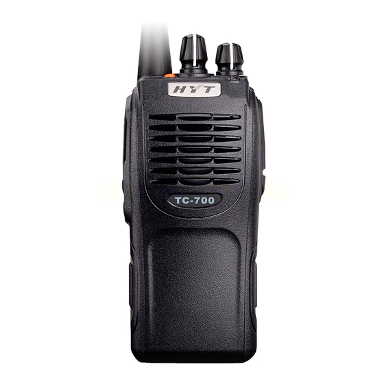
Page 4: Brief Introduction
TC-700 Service Manual Brief Introduction Control Knob and Function Key PTT Key(Push-To-Talk Key) Select transmit/receive mode. Press and hold PTT, radio operates in transmit mode. Release PTT, radio returns to receive mode. SK1 Key Side Key1, programmable key SK2 Key... - Page 5 TC-700 Service Manual Power/Volume Control Knob Rotate the Power/Volume Control Knob clockwise to turn the radio on; fully counter clockwise to turn the radio off. Increase or decrease volume by adjusting the volume control accordingly. (10) LED Indicator Red LED glows while transmitting; green LED glows while receiving; red LED flashes when the battery voltage is low.
-
Page 6: Software Specification
TC-700 Service Manual Software Specification Specification: Conventional Mode 1. Mechanical Knob (16 channels) VHF:136~174MHz UHF:300~350MHz, 350~390MHz, 400~450MHz 420~470MHz, 440~490MHz, 470~520MHz 2. Channel Spacing: 25/20/12.5KHz (Wide/Medium/Narrow bandwidth compatible) 3. Step: 2.5/5/6.25KHz 4. LED Indicator: Red/Green 5. 3 Programmable Function Keys 6. - Page 7 TC-700 Service Manual selected channel and press PTT, the radio data is all reset (All clone modes will be automatically activated when All Reset is completed). Frequency settings are shown as follows: Selected Channel F1 (MHz) F2 (MHz) F3 (MHz)
- Page 8 TC-700 Service Manual Wireless Clone Mode Select wireless clone from optional functions in programming software, turn the power on while holding down PTT and SK1 key simultaneously for 2 seconds, then the source and target radios enter wireless clone mode with orange LED flashing one time (After the source and target radios are turned on and stay in the same channel, hold down PTT on the source radio to begin cloning).
- Page 9 TC-700 Service Manual TK key Use to toggle the channel bandwidth among 25 KHz, 20 KHz and 12.5 KHz. Red LED flashes once when the bandwidth is 25 KHz. PTT/SK1 PTT→ Increase SK1→ Decrease PTT/SK1 is pressed to adjust upward/downward. Red LED glows indicating the maximum adjust value and green LED indicating the minimum value.
- Page 10 TC-700 Service Manual First Group of Adjustment Items Channel No. Adjustment Item Remarks 25KHz 20KHz 12.5KHz TX power LOW 5 point tuning CDCSS PLL balance 3 point tuning (wideband) 1 point tuning CDCSS deviation 3 point tuning (wideband) 1 point tuning...
- Page 11 TC-700 Service Manual Second Group of Adjustment Items Adjustment Channel No. Item Remarks 25KHz 20KHz 12.5KHz RX sensitivity 5 point tuning 1 point tuning AK2346 volume (RX) 1 point tuning (wideband) 1 point tuning (narrowband) 1 point tuning Squelch level 3 (OPEN)
-
Page 12: Circuit Description
TC-700 Service Manual Circuit Description 1. Power Supply Power supply of the radio is derived from the battery, which supplies battery B+ after passing through fuse 3A and then feeds through power switch. The power supplies voltage for three AVRs. IC504 supplies 5V (M5V) voltage for the control circuit. - Page 13 TC-700 Service Manual 1) PLL Circuit Step frequency of PLL can be 2.5 KHz, 5.0 KHz or 6.25 KHz. A 16.8MHz reference oscillator signal is divided at IC301 by a counter to generate a 2.5 KHz, 5.0 KHz or 6.25 KHz reference frequency. Output signal from VCO is buffer amplified by Q301 and divided at IC301 by a frequency divider.
- Page 14 TC-700 Service Manual 3) IF Amplifier The first IF signal is amplified by Q206 before passing through crystal filter and by Q204 after crystal filter and then enters IF processing chip IC204. The signal from IC204 is mixed with the second oscillator signal again in IC204 to create a 450 KHz second IF signal.
- Page 15 TC-700 Service Manual 3) Antenna Switch and LPF Output signal from RF amplifier passes through a low-pass filter network and a transmit/receive switch circuit comprised of D102,D103 and D104 before it reaches the antenna terminal. D103 and D104 is turned on (conductive) in transmit mode and off (isolated) in receive mode.
- Page 16 TC-700 Service Manual 3) MSK Transmit: MSK signal produced by base band processing IC enters VCO together with AF signal for modulation. Receive: MSK input of demodulating IC is sent to AK2346 for demodulation after being amplified. The demodulated signal is then sent to MCU for decoding.
-
Page 17: Cpu Pins
TC-700 Service Manual CPU Pins 1. CPU pins are as follows: MCU Port Name Port Name Input/Output Features P94/DA1 APC/TV Automatic Power Control DTMF/2-5Tone/Beep tone output/ ALARM P93/DA0 TONEO tone output P92/TB2IN SHIFT Clock beat-frequency BYTE BYTE CNVSS CNVSS P87/XCIN... - Page 18 TC-700 Service Manual COM1 COM2 P57/RDY EEDAT EEPROM DATA, date input/output. P56/ALE EECLK EEPROM CLK P55/HOLD P54/HLDA AFDIR AK2346 DIR P53/BLCK AFSCK 2346 SCLK P52/RD P51/BHE AFDT 2346 TDATA P50/WR P47/CS3 CODIO Common date control (AK2346 DATA). P46/CS2 P45/CS1 SAVE...
- Page 19 TC-700 Service Manual P15/INT3 Top Key DC-Switch PLL_UL PLL unlock detect PLL_STB PLL strobe output MICMUTE MICMUTE P07/D7 Option1 Programming cable detect. P06/D6 PLL_DATA PLL date input P05/D5 PLL_CLK PLL clock output P04/D4 Receive/transmit control P03/D3 APC-Switch P02/D2 P01/D1 Side Key1...
- Page 20 TC-700 Service Manual TC-700 Part List 1 TC-700 VHF Part List1 Desscription Ref. No. Print No. 3101051500020 Chip resistor 0402 15PF J 50V C100 3101051020010 Chip resistor 0402 1000PF K 50V C101 3101051500020 Chip resistor 0402 15PF J 50V C102...
- Page 21 TC-700 Service Manual TC-700 Part List 1 TC-700 VHF Part List1 Desscription Ref. No. Print No. 3101054710010 Chip resistor 0402 470PF K 50V C153 3101054710010 Chip resistor 0402 470PF K 50V C154 3101051020010 Chip resistor 0402 1000PF K 50V C155...
- Page 22 TC-700 Service Manual TC-700 Part List 1 TC-700 VHF Part List1 Desscription Ref. No. Print No. 3101051030020 Chip resistor 0402 0.01UF K 25V C250 3101053300000 Chip resistor 0402 33PF J 50V C251 3101051010030 Chip resistor 0402 100PF J 50V C252 3101051030020 Chip resistor 0402 0.01UF K 25V...
- Page 23 TC-700 Service Manual TC-700 Part List 1 TC-700 VHF Part List1 Desscription Ref. No. Print No. 3101051020010 Chip resistor 0402 1000PF K 50V C332 3101051040060 Chip resistor 0402 0.1UF K 10V C334 3101051000020 Chip resistor 0402 10PF D 50V C335 3104074750030 Ta-capacitor 0805 4.7UF M 10V...
- Page 24 TC-700 Service Manual TC-700 Part List 1 TC-700 VHF Part List1 Desscription Ref. No. Print No. 3101054710010 Chip resistor 0402 470PF K 50V C426 3101054730000 Chip resistor 0402 0.047UF K 10V C427 3101051820000 Chip resistor 0402 1800PF K 50V C430 3101051040060 Chip resistor 0402 0.1UF K 10V...
- Page 25 TC-700 Service Manual TC-700 Part List 1 TC-700 VHF Part List1 Desscription Ref. No. Print No. 3101054710010 Chip resistor 0402 470PF K 50V C499 3101051020010 Chip resistor 0402 1000PF K 50V C512 3101051500020 Chip resistor 0402 15PF J 50V C514...
- Page 26 TC-700 Service Manual TC-700 Part List 1 TC-700 VHF Part List1 Desscription Ref. No. Print No. 3005051020000 Array resistor 0402 1K*2 J 1/16W*2 CP514 3005051020000 Array resistor 0402 1K*2 J 1/16W*2 CP516 3005051020000 Array resistor 0402 1K*2 J 1/16W*2 CP517...
- Page 27 Power supply managing IC (voltage regulator) XC6201P502PR IC504 3619006005220 Low voltage detecting IC R3111N451C IC505 3610045000010 SCM M30624FGPGP#U5C 16-BIT IC506 4301080000020 Touch switch TC-700 emergency (SKRTLAE010) K503 3210306180000 Multi-layer inductor 0603 18nH L100 Multi-layer inductor 0603 27nH L101 3210306270000 3210306820000...
- Page 28 TC-700 Service Manual TC-700 Part List 1 TC-700 VHF Part List1 Desscription Ref. No. Print No. 3213306682000 Multi-layer inductor 0603 6.8uH L313 3221506601000 Chip ferrite bead 0603 600Ω± 25% L314 3213212561000 Multi-layer inductor 1008 0.56uH L315 3221506601000 Chip ferrite bead 0603 600Ω± 25%...
- Page 29 TC-700 Service Manual TC-700 Part List 1 TC-700 VHF Part List1 Desscription Ref. No. Print No. 3403008000070 Transistor DTC144EE(TL) Q505 3403008000010 Transistor DTC114EE(TL) Q506 3403008000010 Transistor DTC114EE(TL) Q507 3001053320000 Chip resistor 0402 3.3KΩ J 1/16W R101 3001054730000 Chip resistor 0402 47KΩ J 1/16W...
- Page 30 TC-700 Service Manual TC-700 Part List 1 TC-700 VHF Part List1 Desscription Ref. No. Print No. 3001052230010 Chip resistor 0402 22KΩ J 1/16W R206 3001052230010 Chip resistor 0402 22KΩ J 1/16W R207 3001052230010 Chip resistor 0402 22KΩ J 1/16W R208 3001054720000 Chip resistor 0402 4.7KΩ...
- Page 31 TC-700 Service Manual TC-700 Part List 1 TC-700 VHF Part List1 Desscription Ref. No. Print No. 3001054720000 Chip resistor 0402 4.7KΩ J 1/16W R313 3001053910000 Chip resistor 0402 390Ω J 1/16W R314 3001050000000 Chip resistor 0402 0Ω J 1/16W R315 3001052220000 Chip resistor 0402 2.2KΩ...
- Page 32 TC-700 Service Manual TC-700 Part List 1 TC-700 VHF Part List1 Desscription Ref. No. Print No. 3001051040010 Chip resistor 0402 100KΩ J 1/16W R428 3001051040010 Chip resistor 0402 100KΩ J 1/16W R429 3001051040010 Chip resistor 0402 100KΩ J 1/16W R430 3001052230010 Chip resistor 0402 22KΩ...
- Page 33 TC-700 Service Manual TC-700 Part List 1 TC-700 VHF Part List1 Desscription Ref. No. Print No. 3001053340000 Chip resistor 0402 330KΩ J 1/16W R481 3001051030000 Chip resistor 0402 10KΩ J 1/16W R482 3001051230000 Chip resistor 0402 12KΩ J 1/16W R483 3001052230010 Chip resistor 0402 22KΩ...
- Page 34 TC-700 Service Manual TC-700 Part List 1 TC-700 VHF Part List1 Desscription Ref. No. Print No. 3001051020010 Chip resistor 0402 1KΩ J 1/16W R551 3001051020010 Chip resistor 0402 1KΩ J 1/16W R553 3001051020010 Chip resistor 0402 1KΩ J 1/16W R555 3001054730000 Chip resistor 0402 47KΩ...
- Page 35 TC-700 Service Manual TC-700 Part List 1 TC-700 U(2) Part List1 Part Description Qty Ref. No. Print No. 3101052200010 Chip capacitor 0402 22PF J 50V C100 3101054710010 Chip capacitor 0402 470PF K 50V C101 3101054710010 Chip capacitor 0402 470PF K 50V...
- Page 36 TC-700 Service Manual TC-700 Part List 1 TC-700 U(2) Part List1 Part Description Qty Ref. No. Print No. 51 3101050600010 Chip capacitor 0402 6PF B 50V C157 52 3101054710010 Chip capacitor 0402 470PF K 50V C158 53 3101051040060 Chip capacitor 0402 0.1UF K 16V...
- Page 37 TC-700 Service Manual TC-700 Part List 1 TC-700 U(2) Part List1 Part Description Qty Ref. No. Print No. 101 3101050400010 Chip capacitor 0402 4PF B 50V C257* 102 3101051010030 Chip capacitor 0402 100PF J 50V C258 103 3101051200020 Chip capacitor 0402 12PF J 50V...
- Page 38 TC-700 Service Manual TC-700 Part List 1 TC-700 U(2) Part List1 Part Description Qty Ref. No. Print No. 151 3101051040060 Chip capacitor 0402 0.1UF K 16V C345 152 3101051020010 Chip capacitor 0402 1000PF K 50V C347 153 3101051030020 Chip capacitor 0402 0.01UF K 25V...
- Page 39 TC-700 Service Manual TC-700 Part List 1 TC-700 U(2) Part List1 Part Description Qty Ref. No. Print No. 201 3104074750030 Ta-capacitor0805 4.7UF M 10V C452 202 3101051040060 Chip capacitor 0402 0.1UF K 16V C458 203 3101051040060 Chip capacitor 0402 0.1UF K 16V...
- Page 40 TC-700 Service Manual TC-700 Part List 1 TC-700 U(2) Part List1 Part Description Qty Ref. No. Print No. 251 3101051050000 Chip capacitor 0402 1UF K 6.3V C525 252 3104071060010 Ta-capacitor 0805 10UF M 6.3V C526 253 3101054710010 Chip capacitor 0402 470PF K 50V...
- Page 41 Power managing IC (voltage regulator) XC6201P502PR IC504 342 3619006005220 Low voltage detecting IC R3111N451C-TR-F IC505 343 3610045000010 SCM M30624FGPGP#U5C IC506* 344 4301080000020 Touch switch TC-700 emergency (SKRTLAE010) K503 345 3210305180000 Multi-layer inductor 0402 18nH L102* 346 3210305150010 Multi-layer inductor 0402 15nH L103* 347 3221506601000 Chip ferrite bead 0603 600Ω±...
- Page 42 TC-700 Service Manual TC-700 Part List 1 TC-700 U(2) Part List1 Part Description Qty Ref. No. Print No. 351 3210107221000 Framework inductor 0805 220nH L108 352 3231351680000 Air-core inductor E2-0.35*1.6*8TR L109 353 3221507600000 Chip ferrite bead 0805 60Ω± 25% L110 354 3231351640000 Air-core inductor E2-0.35*1.6*4TL...
- Page 43 TC-700 Service Manual TC-700 Part List 1 TC-700 U(2) Part List1 Part Description Qty Ref. No. Print No. 401 3502010000490 2SK3476(TE12L.Q) Q104 402 3403008000030 Transistor DTC114TE Q105 403 3503020000030 FET 2SK1824-T1-A Q107 404 3403008000010 Transistor DTC114EE(TL) Q108 405 3403008000010 Transistor DTC114EE(TL)
- Page 44 TC-700 Service Manual TC-700 Part List 1 TC-700 U(2) Part List1 Part Description Qty Ref. No. Print No. 451 3001054730000 Chip resistor 0402 47KΩ J 1/16W R117 452 3001053320000 Chip resistor 0402 3.3KΩ J 1/16W R118 453 3001070000000 Chip resistor 0805 0Ω J 1/8W...
- Page 45 TC-700 Service Manual TC-700 Part List 1 TC-700 U(2) Part List1 Part Description Qty Ref. No. Print No. 501 3001052210000 Chip resistor 0402 220Ω J 1/16W R225 502 3001052700000 Chip resistor 0402 27Ω J 1/16W R226 503 3001056820000 Chip resistor 0402 6.8KΩ J 1/16W...
- Page 46 TC-700 Service Manual TC-700 Part List 1 TC-700 U(2) Part List1 Part Description Qty Ref. No. Print No. 551 3001051000000 Chip resistor 0402 10Ω J 1/16W R349 552 3001051000000 Chip resistor 0402 10Ω J 1/16W R350 553 3001051540000 Chip resistor 0402 150KΩ F 1/16W...
- Page 47 TC-700 Service Manual TC-700 Part List 1 TC-700 U(2) Part List1 Part Description Qty Ref. No. Print No. 601 3001053940000 Chip resistor 0402 390KΩ J 1/16W R449 602 3001058230000 Chip resistor 0402 82KΩ J 1/16W R450 603 3001051830000 Chip resistor 0402 18KΩ J 1/16W...
- Page 48 TC-700 Service Manual TC-700 Part List 1 TC-700 U(2) Part List1 Part Description Qty Ref. No. Print No. 651 3001052230010 Chip resistor 0402 22KΩ J 1/16W R499 652 3001054730000 Chip resistor 0402 47KΩ J 1/16W R502 653 3001050000000 Chip resistor 0402 0Ω J 1/16W...
- Page 49 TC-700 Service Manual TC-700 Part List 1 TC-700 U(2) Part List1 Part Description Qty Ref. No. Print No. Remark 701 3003992220000 Thermistor 0603 2.2KΩ J 100mW TH301 702 3002996830000 Trimmer resistor (2*2) 68KΩ(+25%) 703 3701016850010 TXCO 16.8MHz 5V X301 704 3702368630020 Crystal 3.6864MHz...
-
Page 50: Adjustment Description
TC-700 Service Manual Adjustment Description Adjust the radio by PC programming software or by manual adjustment. In manual adjustment mode, the adjustment method is shown as follows: (Refer to “ Software Specification”for the manual adjustment mode) Required Test Instrument Radio Communication Test Set... - Page 51 TC-700 Service Manual SK2 key Used to set the frequency. 1 point tuning is used to adjust center frequency, 3 point tuning adjusts F1, F3, F5 and 5 point tuning adjusts F1-F5. The frequency toggles from low frequency to high frequency.
- Page 52 Adjustment Method Turn the power on by holding down TK and SK2 key simultaneously for 2 seconds, the radio enters manual adjust mode with red LED flashes twice. Refer to Manual Adjust Mode in TC-700 Software Specification for more details.
- Page 53 TC-700 Service Manual Enter the adjust mode. Turn to CH6. Adjust at 3 6. CTCSS PTT key (increase) point (wideband), 1 point (254.1Hz) SK1 key (medium band) and 1 deviation (decrease) High point (narrowband) respectively. Radio Adjust deviation to Enter the adjust mode.
- Page 54 TC-700 Service Manual Adjust power to 5W(4W)± 0.1W Enter the adjust mode. PTT key (increase) Group 1 11. TX power Radio VHF: 5W, Turn to CH13. Adjust at 5 SK1 key (decrease) HIGH Communication UHF: 4W point (wideband). Test Set TX TEST Enter the adjust mode.
- Page 55 TC-700 Service Manual Receiver Item Condition Test Method Purpose Instrument Enter the adjust mode. Turn to PTT key Adjust level to 1. RX CH1. SK1 key 119dBm. sensitivity Adjust at 5 point (wideband). SINAD≥12dB Enter the adjust mode. Turn to PTT key When Max.
-
Page 56: Trouble-Shooting Chart
TC-700 Service Manual Trouble-shooting Chart MCU Check Normal power-on The RF circuit can’t Check the alert tone? be driven. control circuit Replace Speaker works the speaker well? Check the Read circuit of read 9.8304MHz works available? frequency normally? Reset Exchange... - Page 57 TC-700 Service Manual Check Power supply is Exchange normal? Q306 Exchange Oscillator CV voltage in Check if Q305 Q305 Rx is normal? works well. Check Check if Q304 output normally? Q304 Check Check if feedback Q301 is normal. Check power Check if 16.8MHz...
- Page 58 TC-700 Service Manual...
- Page 59 TC-700 Service Manual...
-
Page 60: Disassembly And Assembly For Repair
TC-700 Service Manual Disassembly and Assembly for Repair 1. Remove the case assembly from the chassis (as shown in Fig. 1) 1. Remove the volume knob and channel knob①. 2. Remove the two screws ②. 3. Lift the both sides of chassis from the case assembly ③. - Page 61 TC-700 Service Manual 5. Remove the solder of the positive and negative terminal on the battery’ s connector with a soldering iron ⒀. 6. Lift and remove the main unit board ⒁ from the chassis. Fig. 3 Cautions for assembly: 4.
- Page 62 TC-700 Service Manual Fig. 5 Fig. 6...
-
Page 63: Exploded View
TC-700 Service Manual Exploded View TX-RX Unit... - Page 64 TC-700S Mic holder Black 1.00 6300016000000 TC-700S Aluminum chassis 1.00 7300001000000 TC700S PTT metal dome (3-key) 1.00 4210047000000 TC-700 Key board connection cable 47mm 0.50 4100700101100 TC-700S PT PCB FR4 0.6T/2L 1.00 7500114000000 TC500 Gap pad 1.00 4400000000000 SMA-type MSMA1551D5-001-NT3G-50 connector Male 1.00...
- Page 65 TC-700 Service Manual 3801045030090 Ceramic filter 450KHz±6.0KHz 1.00 6000128000000 TC-700 Battery latch Black 1.00 6201078000000 TC-700S Battery latch baffle 1.2mmSUS304 1.00 7000036000000 TC-700S Spring Ф 0.35*Ф 2.3*10mm 2.00 6000133000000 TC-700S Main unit front case Black 1.00 7101904020020 Self-tapping ST1.9*4.0mm 13.00 7102504000300 Machine screw M2.5*4.0mm Ultra-thin cross-head...
-
Page 66: Packing
TC-700 Service Manual Packing... -
Page 67: Pc Board View
TC-700VHF PC Board View Top Layer... - Page 68 TC-700VHF PC Board View Bottom Layer...
- Page 69 TC-700UHF PC Board View Top Layer...
- Page 70 TC-700UHF PC Board View Bottom Layer...
-
Page 71: Block Diagram
TC-700 Block Diagram... -
Page 72: Level Diagram
TC-700 Level Diagram TC 700 Level Diagram Rx Section -109dBm -120dBm 130mVrms -113dBm -120dBm -101dBm -103dBm -105dBm 250mVrms 300mVrms 100mVrms C251 C236 C238 IC408 IC202 IC202 XF203 IC204 IC404 C487 C254 Q207 C135 C312 C241 Q206 C230 Q204 K501 1st Local... -
Page 73: Schematic Diagram
TC-700V Schematic Diagram(Base Band&AF Amplify) R468 C602 ZD401 SWB+ SWB+ 220p EDZ6.8B K501 L501 F501 J502 BLM21P221SG Q404 IC401 J401 J501 R601 2SK1824 R604 R607 TDA2822 8.2k C609 C608 BATTSEL R602 R456 BATTSEL R548 C558 C517 D501 C518 0.1uF INPUT-1 OUTPUT1 R411 C603... - Page 74 TC-700V Schematic Diagram (CPU) C535 D503 SWB+ SWB+ C534 470p 1SS373 C537 C536 C533 C532 470p 10u6.3 470p IC504 XC6201P502R K507 L503 K506 0.22UH MONI K504 IC501 C512 R508 1000P EECLK TEST K503 GGND EEDAT EECLK ALARM COM2 EEDAT NCON NCON COM1 AFCO...
- Page 75 TC-700V Schematic Diagram (TX&RX) ANT100 C137 C139 C141 Antenna ANT SW C131 C135 1000p D102 L111 L112 L118 L119 L113 L114 TX FINAL AMP MA77 03191030 03193540 03193530 Q104 C117 L115 R114 L107 2SK3476 C119 C125 C126 C127 C130 C134 C136 C138 C140...
- Page 76 TC-700V Schematic Diagram (VCO&PLL) C302 R301 C301 1000p C359 2.73V L301 L322 C358 1000p R306 R302 C361 C360 Q301 220k 2SC5108(Y) C303 10p(B) PLL_Fin RF AMP T: 3.73V TX VCO OSCILATION R: 0 V D303 Q302 RF BUFFER AMP HVC376B R305 2SK508NV C157...
- Page 77 TC700-U Schematic Diagram (Base Band&AF Amplifier) R468 SWB+ SWB+ C602 ZD401 K501 220p EDZ6.8B F501 L501 J502 BLM21P221SG R604 R436 J501 IC401 J401 R601 TDA2822 Q404 8.2K BATTSEL R602 R456 C558 C517 C518 C608 2SK1824 C603 BATTSEL R548 C609 INPUT-1 OUTPUT1 R411 EDZ6.8B x 2...
- Page 78 TC700-U Schematic Diagram (CPU) D503 C535 1SS373 470p SWB+ SWB+ 面 右下角附件口注释: PCB top 从左至右依次为: C537 C533 C532 C534 C536 470p 470p COM4 ( CPU PIN33 ) 10u6.3 COM3 ( CPU PIN34 ) IC504 COM1 ( CPU PIN35 ) XC6201P502R COM2 (...
- Page 79 TC700-U Schematic Diagram (TX&RX) C141 C137 C139 ANT100 1.5P ANTENNA C131 C135 R120 D102 L112* L113* L114* 100P MA77 470p L107* C117 R114* C163* 2.2n Q104 C136* 1000p C138* C140* 4.5P C142* L115 2SK3476 1.5P C105* R106 C110* R109 C111 C125* C126* C164*...
- Page 80 C302 R301 C301 C359 TC700-U Schematic Diagram (VCO&PLL) L322 470p C358 L301 470p R302 C361 C360 Q301 150K 2SC5108(Y) C303 10p(B) R305 D303 C311 C355 L321 3.8V C157 470p 0.1U HVC350B 100N C312 R:2.3V RFosc L302 C305* L304* 0.5P C313 C100 C309* T:2.4V...
-
Page 81: Description Of Tc-700 Desktop Charger
Description of TC-700 Desktop Charger Ⅰ. General Description The charger is developed & designed for TC-700 wireless series. The charger adopts bq2000T——a programmable multi-chemistry fast-charge management IC. The charger is for fast-charge management of nickel cadmium (Ni-Cd), nickel metal-hydride (Ni-MH), or lithium-ion (Li-Ion) batteries in single or multi-chemistry applications. - Page 82 TC-700 Service Manual Pin Names and Descriptions: SNS: Current-sense input Enables the bq2000T to sense the battery current via the voltage developed on this pin by an external sense-resistor connected in series with the battery pack. Vss: System ground LED: Charge-status output Open-drain output that indicates the charging status by turning on, turning off, or flashing an external LED.
- Page 83 TC-700 Service Manual Charge Termination 1. Maximum Charge Time (NiCd, NiMH, and Li-Ion) The bq2000T sets the maximum charge-time through pin RC. With the proper selection of external resistor and capacitor, various time-out values may be achieved. Figure Ⅱshows a typical connection.
- Page 84 TC-700 Service Manual Figure Ⅳ Battery Voltage Divider For Li-Ion battery packs, the resistor values R and R are calculated by the following equation: Where N is the number of cells in series. The end-to-end input impedance of this resistive divider network should be at least 200KΩ...
-
Page 85: Specifications
TC-700 Service Manual Ⅲ. Specifications 1. Output voltage and current Input: 12±3V 1000mA Output: 8-12V 20~1000mA (Input: 12V 1000mA DC Output: 800mA DC) 2. Charging current 1) Li-ion battery Fast charging current: 800±200mA Minimum charging current: 75±20mA 2) Ni-MH battery Fast charging current: 850±100 mA... - Page 86 PCB Board View (TC-700 Desktop Charger) Bottom Layer...
- Page 87 PC Board View (TC-700 Desktop Charger) Top Layer PDF 文件使用 "pdfFactory Pro" 试用版本创建 www.fineprint.com.cn...
- Page 88 TC-700 Desktop Charger Schematic Diagram FMMT718 BAT+ FUSE1 220uH 1N5401 R19 (NC) 1N4004 47uF 35V 1N5821 2N3904 1N4004 330Ω 2N3904 10K D 1N4735A 1000p 2N3904 R20 (NC) C11 (NC) 330Ω 10uF 25V 4.7P 2.2K 470K D 0.33u 1000p 18K D...
- Page 89 TC-700 Service Manual Specifications General VHF: 136-174MHz Frequency Range UHF:300-350MHz,350-390MHz, 400-450MHz, 420-470MHz 440-490MHz,470-520MHz Number of Channels Channel Spacing 25 /20/12.5 KHz Operating Voltage 7.4 V Battery Life About 14 hours ( 5-5-90 duty cycle) Operating Temperature Range -30℃ — +60℃...
Need help?
Do you have a question about the TC-700 and is the answer not in the manual?
Questions and answers