Table of Contents
Advertisement
Quick Links
Advertisement
Table of Contents

Related Manuals for HYT TC-500


Summary of Contents for HYT TC-500
- Page 1 8130050000120 2007-12-25...
-
Page 2: Table Of Contents
TC-500 Service Manual Content Revision History-----------------------------------------------------------------------------------------------2 General-----------------------------------------------------------------------------------------------------------2 Radio Overview------------------------------------------------------------------------------------------------3 Software Specification--------------------------------------------------------------------------------------5 Circuit Description------------------------------------------------------------------------------------------9 CPU Pins-------------------------------------------------------------------------------------------------------13 Parts List 1-----------------------------------------------------------------------------------------------------15 Adjustment Description-----------------------------------------------------------------------------------59 Disassembly and Assembly for Repair--------------------------------------------------------------63 Exploded View------------------------------------------------------------------------------------------------66 Part List 2------------------------------------------------------------------------------------------------------67 Packing---------------------------------------------------------------------------------------------------------68 PCB View-------------------------------------------------------------------------------------------------------69 Block Diagram------------------------------------------------------------------------------------------------73 Schematic Diagram-----------------------------------------------------------------------------------------74 Specifications------------------------------------------------------------------------------------------------76... -
Page 3: Revision History
TC-500 Service Manual Revision History Version Date Content of Update Circuit: 1. Update the parts list 1, schematic diagram, block September,2007 diagram, PCB View and some parameters of specifications. Structure: update parts list 2, exploded view. General Manual Scope This manual is intended for use by experienced technicians familiar with similar types of communication equipment. -
Page 4: Radio Overview
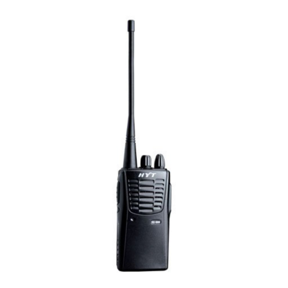
TC-500 Service Manual Radio Overview Antenna LED Indicator The light will glow red during transmission. The light will glow green during receiving. During transmission, the light flashes red when the battery voltage is low. Channel Selector Knob Turn the Channel Selector Knob to select from channels 1-16 (Channel 16 can be programmed by your dealer as scan function). - Page 5 TC-500 Service Manual External Jack Remove the jack cover and insert an earphone; or insert programming cable into the jack to program the radio via programming software. 10. Battery 11. Belt Clip Used to clip radio on your belt. 12. Battery Latch Used to fasten and remove the battery.
-
Page 6: Software Specification
Radio Modes User Mode User mode is conventional communication mode. Turn the power on while disconnecting the two SELF points, the radio enters user mode. (Refer to “ TC-500 Owner’ s Manual”for details about operation in this mode.) Model Set Mode 1. - Page 7 6. Turn off the radio and then disconnect the two SELF points on PCB to complete the model setting. For example, if MS1 of TC-500-U (450.000~469.995MHz) is 0 (See the initial data table) and its number refers to 7, then it is unnecessary to short out MS1 and MS2. To initialize its model and channel data, you can operate as following: (1) Short out the two SELF points on PCB;...
- Page 8 TC-500 Service Manual Manual Adjust Mode If manual adjust mode is enabled, turn on the radio while holding down PTT and MONI simultaneously, the radio enters manual adjust mode after 2 seconds. Choose the adjusting items by turning the Channel Selector Knob to CH1-CH7 position; use PTT (upwards) or MONI (downwards) to adjust (Note: Microphone jack shouldn’...
- Page 9 TC-500 Service Manual Initial data table 1CH(Center) 2CH(Low) 3CH(High) 9-16CH Model Frequency (MHz) (MHz) Tx (MHz) Rx (MHz) Tx (MHz) Rx (MHz) Tx (MHz) Rx (MHz) (MHz) (MHz) (MHz) (MHz) (MHz) (MHz) 150.000~173.995 +21.4 162.000 162.100 150.000 150.100 173.975 173.900 162.500...
-
Page 10: Circuit Description
TC-500 Service Manual Circuit Description Frequency Configuration The receiver utilizes double conversion superheterodyne. The first IF is 21.4MHz and the second is 455KHz. The first local oscillator signal is supplied from PLL circuit. Frequency needed in the transmitter is supplied from PLL circuit. Figure 1 shows the frequency configuration. - Page 11 TC-500 Service Manual synthesizer in the first mixer (Q23) to generate a 21.4MHz first IF signal. The first IF signal is then fed through two monolithic crystal filters (XF1) to remove spurious signals from adjacent channels. 3. IF Amplifier The first IF signal is amplified in Q22 and then enters the IF process chip IC1. The signal is mixed with the second local oscillator signal in IC1 to create a 455KHz second IF signal.
- Page 12 TC-500 Service Manual matches the preset value and controls the MUTE and AFCO and the speaker sound output according to the squelch results. PLL Frequency Synthesizer PLL circuit generates the first local oscillator signal for reception and the RF signal for transmission.
- Page 13 TC-500 Service Manual Transmitter Transmit audio The audio signal from microphone is amplified through IC3, and then pre -emphasized , and then filtered by another low-pass filter(separate filter)(Q25 and Q24) to eliminate the frequencies over 3KHz. The resulting signal enters the VCO for direct FM modulation. (See figure 5)
-
Page 14: Cpu Pins
TC-500 Service Manual CPU Pins PIN No. PIN NAME DESCRIPTION CTCSS/CDCSS input BUSY Input busy signal BATT Detect battery voltage TIBI CTCSS/CDCSS exterior circuit central point input SAVE Power saving control H: OFF L: ON TXLow Transmitter power control H: Low power L: High power... - Page 15 TC-500 Service Manual MONIK MONI key input ENC0 ENC1 Channel Selector Knob encode input ENC2 ENC3 Audio muting control MUTE Audio power control TONE5 CTCSS code output TONE4 CTCSS code output TONE3 CTCSS code output TONE2 CTCSS code output TONE1...
-
Page 16: Parts List 1
TC-500 Service Manual Parts List 1 TC-500 VHF (136-150MHz) Material No. Description Qty. Ref.No. Address 3001051030000 Chip resistor 0402 10KΩ 3001060000000 Chip resistor 0603 0Ω 3001060000000 Chip resistor 0603 0Ω 3001060000000 Chip resistor 0603 0Ω 3001060000000 Chip resistor 0603 0Ω... - Page 17 TC-500 Service Manual Material No. Description Qty. Ref.No. Address 3001061030010 Chip resistor 0603 10KΩ 3001061030010 Chip resistor 0603 10KΩ 3001061030010 Chip resistor 0603 10KΩ 3001061040010 Chip resistor 0603 100KΩ 3001061040010 Chip resistor 0603 100KΩ 3001061040010 Chip resistor 0603 100KΩ 3001061040010 Chip resistor 0603 100KΩ...
- Page 18 TC-500 Service Manual Material No. Description Qty. Ref.No. Address 3001061840000 Chip resistor 0603 180KΩ 3001061850000 Chip resistor 0603 1.8MΩ R155 3001061850000 Chip resistor 0603 1.8MΩ R156 3001062030000 Chip resistor 0603 20KΩ 3001062220000 Chip resistor 0603 2.2KΩ R114 3001062220000 Chip resistor 0603 2.2KΩ...
- Page 19 TC-500 Service Manual Material No. Description Qty. Ref.No. Address 3001064700000 Chip resistor 0603 47Ω R125 3001064700000 Chip resistor 0603 47Ω R191 3001064710000 Chip resistor 0603 470Ω 3001064710000 Chip resistor 0603 470Ω R166 3001064720000 Chip resistor 0603 4.7KΩ R121 3001064720000 Chip resistor 0603 4.7KΩ...
- Page 20 TC-500 Service Manual Material No. Description Qty. Ref.No. Address 3005991030070 Resistor array 0603 10KΩ*4 3005991030070 Resistor array 0603 10KΩ*4 3099080398000 Chip resistor 1206 0.39Ω R188 3099080398000 Chip resistor 1206 0.39Ω R189 3099080398000 Chip resistor 1206 0.39Ω 3101050100030 Chip capacitor 0402 1PF...
- Page 21 TC-500 Service Manual Material No. Description Qty. Ref.No. Address 3101051020010 Chip capacitor 0402 1000PF 3101051020010 Chip capacitor 0402 1000PF 3101051020010 Chip capacitor 0402 1000PF 3101051020010 Chip capacitor 0402 1000PF 3101051020010 Chip capacitor 0402 1000PF 3101051020010 Chip capacitor 0402 1000PF 3101051020010...
- Page 22 TC-500 Service Manual Material No. Description Qty. Ref.No. Address 3101052210010 Chip capacitor 0402 220PF C239 3101052230000 Chip capacitor 0402 0.022UF C151 3101052230000 Chip capacitor 0402 0.022UF C167 3101052230000 Chip capacitor 0402 0.022UF C168 3101052230000 Chip capacitor 0402 0.022UF C169 3101052230000 Chip capacitor 0402 0.022UF...
- Page 23 TC-500 Service Manual Material No. Description Qty. Ref.No. Address 3101054710010 Chip capacitor 0402 470PF 3101054710010 Chip capacitor 0402 470PF 3101054710010 Chip capacitor 0402 470PF 3101054710010 Chip capacitor 0402 470PF 3101054730000 Chip capacitor 0402 0.047UF C157 3101054730000 Chip capacitor 0402 0.047UF...
- Page 24 TC-500 Service Manual Material No. Description Qty. Ref.No. Address 3104082250030 Tantalum capacitor 1206 2.2UF C165 3104084750030 Tantalum capacitor 1206 4.7UF C117 3104084750030 Tantalum capacitor 1206 4.7UF C120 3104084750030 Tantalum capacitor 1206 4.7UF C173 3104086850000 Tantalum capacitor 1206 6.8UF± 20% C112...
- Page 25 TC-500 Service Manual Material No. Description Qty. Ref.No. Address 3304010100690 Varactor 1SV269(TPH2.F) 34V 3304010101090 Varactor 1SV283(TPH3.F.T) 3304010101090 Varactor 1SV283(TPH3.F.T) 3304060300040 Varactor HVC362TRF-E 3307110100070 LED KPT-1608SR 3307110100080 LED KPT-1608SGC 3399990000160 Varactor MA2Z36000L 3401001000080 Transistor 2SA1362-GR(TE85.F) 3401002000990 Transistor 2SC5108-Y(TE85L.F) 3401002000990 Transistor 2SC5108-Y(TE85L.F) 3401002000990 Transistor 2SC5108-Y(TE86L.F)
- Page 26 TC-500 Service Manual Material No. Description Qty. Ref.No. Address 3609004005280 Reset IC PST9140NR 3610004000340 SCM M38223M4A IC11 3612031004400 Memory AT24C08AN 3701737230040 Crystal oscillator 7.3728MHz 4100500101930 TC-500V PCB FR4 1.0T/4L/4P...
- Page 27 TC-500 Service Manual TC-500 VHF (150-174MHz) Material No. Description Qty. Ref.No. Address 3001054730000 Chip resistor 0402 47KΩ 3001060000000 Chip resistor 0603 0Ω 3001060000000 Chip resistor 0603 0Ω 3001060000000 Chip resistor 0603 0Ω 3001060000000 Chip resistor 0603 0Ω 3001060000000 Chip resistor 0603 0Ω...
- Page 28 TC-500 Service Manual Material No. Description Qty. Ref.No. Address 3001061030010 Chip resistor 0603 10KΩ 3001061030010 Chip resistor 0603 10KΩ 3001061030010 Chip resistor 0603 10KΩ 3001061040010 Chip resistor 0603 100KΩ 3001061040010 Chip resistor 0603 100KΩ 3001061040010 Chip resistor 0603 100KΩ 3001061040010 Chip resistor 0603 100KΩ...
- Page 29 TC-500 Service Manual Material No. Description Qty. Ref.No. Address 3001061840000 Chip resistor 0603 180KΩ 3001061850000 Chip resistor 0603 1.8MΩ R155 3001061850000 Chip resistor 0603 1.8MΩ R156 3001062030000 Chip resistor 0603 20KΩ 3001062220000 Chip resistor 0603 2.2KΩ R165 3001062220000 Chip resistor 0603 2.2KΩ...
- Page 30 TC-500 Service Manual Material No. Description Qty. Ref.No. Address 3001064700000 Chip resistor 0603 47Ω R125 3001064700000 Chip resistor 0603 47Ω R191 3001064710000 Chip resistor 0603 470Ω 3001064710000 Chip resistor 0603 470Ω R166 3001064720000 Chip resistor 0603 4.7KΩ R114 3001064720000 Chip resistor 0603 4.7KΩ...
- Page 31 TC-500 Service Manual Material No. Description Qty. Ref.No. Address 3099080398000 Chip resistor 1206 0.39Ω R189 3099080398000 Chip resistor 1206 0.39Ω 3101050100030 Chip capacitor 0402 1PF C143 3101050200010 Chip capacitor 0402 2PF C163 3101050400010 Chip capacitor 0402 4PF C164 3101050500010 Chip capacitor 0402 5PF...
- Page 32 TC-500 Service Manual Material No. Description Qty. Ref.No. Address 3101051020010 Chip capacitor 0402 1000PF 3101051020010 Chip capacitor 0402 1000PF 3101051020010 Chip capacitor 0402 1000PF 3101051020010 Chip capacitor 0402 1000PF 3101051020010 Chip capacitor 0402 1000PF 3101051020010 Chip capacitor 0402 1000PF 3101051020010...
- Page 33 TC-500 Service Manual Material No. Description Qty. Ref.No. Address 3101052210010 Chip capacitor 0402 220PF C239 3101052230000 Chip capacitor 0402 0.022UF C151 3101052230000 Chip capacitor 0402 0.022UF C167 3101052230000 Chip capacitor 0402 0.022UF C168 3101052230000 Chip capacitor 0402 0.022UF C169 3101052230000 Chip capacitor 0402 0.022UF...
- Page 34 TC-500 Service Manual Material No. Description Qty. Ref.No. Address 3101054710010 Chip capacitor 0402 470PF 3101054710010 Chip capacitor 0402 470PF 3101054710010 Chip capacitor 0402 470PF 3101054710010 Chip capacitor 0402 470PF 3101054730000 Chip capacitor 0402 0.047UF C157 3101054730000 Chip capacitor 0402 0.047UF...
- Page 35 TC-500 Service Manual Material No. Description Qty. Ref.No. Address 3104084750030 Tantalum capacitor 1206 4.7UF C173 3104086850000 Tantalum capacitor 1206 6.8UF± 20% C112 3104201070000 Tantalum capacitor 2220 100UF C203 3199060758000 Chip capacitor 0603 0.75PF 3210108270000 Bobbin inductor 1206 27nH 3210108330000 Bobbin inductor 1206 33nH...
- Page 36 TC-500 Service Manual Material No. Description Qty. Ref.No. Address 3304060300040 Varactor HVC362TRF 3304060300040 Varactor HVC362TRF 3307110100070 LED KPT-1608SRC 3307110100080 LED KPT-1608SGC 3399990000160 Varactor MA2Z36000L 3401001000080 Transistor 2SA1362-GR(TE85.F) 3401002000990 Transistor 2SC5108-Y(TE85L.F) 3401002000990 Transistor 2SC5108-Y(TE86L.F) 3401002000990 Transistor 2SC5108-Y(TE87L.F) 3403007000000 Transistor DTA114EE(TL) 3403007000020...
- Page 37 TC-500 Service Manual Material No. Description Qty. Ref.No. Address 3609004005280 Reset IC PST9140NR 3610004000340 IC11 3612031004400 Memory AT24C08AN 3701737230040 Crystal oscillator 7.3728MHz 4100500101930 TC-500V PCB FR4 1.0T/4L/4P...
- Page 38 TC-500 Service Manual TC-500 UHF (400-420MHz) Material No. Description Qty. Ref.No. Address 3001054730000 Chip resistor 0402 47KΩ R622 3001060000000 Chip resistor 0603 0Ω 3001060000000 Chip resistor 0603 0Ω 3001060000000 Chip resistor 0603 0Ω 3001060000000 Chip resistor 0603 0Ω 3001060000000 Chip resistor 0603 0Ω...
- Page 39 TC-500 Service Manual Material No. Description Qty. Ref.No. Address 3001061030010 Chip resistor 0603 10KΩ 3001061030010 Chip resistor 0603 10KΩ 3001061030010 Chip resistor 0603 10KΩ 3001061030010 Chip resistor 0603 10KΩ 3001061040010 Chip resistor 0603 100KΩ 3001061040010 Chip resistor 0603 100KΩ 3001061040010 Chip resistor 0603 100KΩ...
- Page 40 TC-500 Service Manual Material No. Description Qty. Ref.No. Address 3001062220000 Chip resistor 0603 2.2KΩ R187 3001062220000 Chip resistor 0603 2.2KΩ 3001062220000 Chip resistor 0603 2.2KΩ 3001062230000 Chip resistor 0603 22KΩ R120 3001062240010 Chip resistor 0603 220KΩ R167 3001062720000 Chip resistor 0603 2.7KΩ...
- Page 41 TC-500 Service Manual Material No. Description Qty. Ref.No. Address 3001064720000 Chip resistor 0603 4.7KΩ 3001064730000 Chip resistor 0603 47KΩ R105 3001064730000 Chip resistor 0603 47KΩ R154 3001064730000 Chip resistor 0603 47KΩ 3001064730000 Chip resistor 0603 47KΩ 3001064730000 Chip resistor 0603 47KΩ...
- Page 42 TC-500 Service Manual Material No. Description Qty. Ref.No. Address 3101050100030 Chip capacitor 0402 1PF 3101050100060 Chip capacitor 0402 1PF C192 3101050200010 Chip capacitor 0402 2PF C104 3101050200010 Chip capacitor 0402 2PF C134 3101050300000 Chip capacitor 0402 3PF C103 3101050300000 Chip capacitor 0402 3PF...
- Page 43 TC-500 Service Manual Material No. Description Qty. Ref.No. Address 3101051020010 Chip capacitor 0402 1000PF 3101051020010 Chip capacitor 0402 1000PF 3101051020010 Chip capacitor 0402 1000PF 3101051020010 Chip capacitor 0402 1000PF 3101051020010 Chip capacitor 0402 1000PF 3101051020010 Chip capacitor 0402 1000PF 3101051020010...
- Page 44 TC-500 Service Manual Material No. Description Qty. Ref.No. Address 3101052210010 Chip capacitor 0402 220PF 3101052210010 Chip capacitor 0402 220PF C239 3101052220010 Chip capacitor 0402 2.2nF C254 3101052230000 Chip capacitor 0402 0.022UF C167 3101052230000 Chip capacitor 0402 0.022UF C168 3101052230000 Chip capacitor 0402 0.022UF...
- Page 45 TC-500 Service Manual Material No. Description Qty. Ref.No. Address 3101054710010 Chip capacitor 0402 470PF 3101054710010 Chip capacitor 0402 470PF 3101054720000 Chip capacitor 0402 4700PF C232 3101054720000 Chip capacitor 0402 4700PF 3101054730000 Chip capacitor 0402 0.047UF C157 3101054730000 Chip capacitor 0402 0.047UF...
- Page 46 TC-500 Service Manual Material No. Description Qty. Ref.No. Address 3104084750030 Tantalum capacitor 1206 4.7UF C173 3104201070000 Tantalum capacitor 2220 100UF C203 3210107221000 Bobbin inductor 0805 220nH 3210108230010 Bobbin inductor 1206 23nH 3210108270000 Bobbin inductor 1206 27nH 3210209102010 Bobbin inductor 1210 1uH...
- Page 47 TC-500 Service Manual Material No. Description Qty. Ref.No. Address 3303210200000 Varactor MA2S37600L 3303210200000 Varactor MA2S37600L 3303210200000 Varactor MA2S37600L 3303210200000 Varactor MA2S37600L 3307110100070 LED KPT-1608SRC 3307110100080 LED KPT-1608SGC 3399990000160 Varactor MA2Z36000L 3399990000220 Diode UDZS3.0B 3401001000080 Transistor 2SA1362-GR(TE85.F) 3401002000990 Transistor 2SC5108-Y(TE85L.F) 3401002000990 Transistor 2SC5108-Y(TE85L.F)
- Page 48 TC-500 Service Manual Material No. Description Qty. Ref.No. Address 3701012850010 TCXO 12.8MHz 3701737230040 Crystal oscillator 7.3728MHz 4100500101650 TC-500US(U) PCB FR4...
- Page 49 TC-500 Service Manual TC-500 UHF (450-470MHz) Material No. Description Qty. Ref.No. Address 3001054730000 Chip resistor 0402 47KΩ R622 3001060000000 Chip resistor 0603 0Ω 3001060000000 Chip resistor 0603 0Ω 3001060000000 Chip resistor 0603 0Ω 3001060000000 Chip resistor 0603 0Ω 3001060000000 Chip resistor 0603 0Ω...
- Page 50 TC-500 Service Manual Material No. Description Qty. Ref.No. Address 3001061040010 Chip resistor 0603 100KΩ 3001061040010 Chip resistor 0603 100KΩ 3001061040010 Chip resistor 0603 100KΩ 3001061040010 Chip resistor 0603 100KΩ 3001061040010 Chip resistor 0603 100KΩ R175 3001061040010 Chip resistor 0603 100KΩ...
- Page 51 TC-500 Service Manual Material No. Description Qty. Ref.No. Address 3001062220000 Chip resistor 0603 2.2KΩ R174 3001062220000 Chip resistor 0603 2.2KΩ 3001062220000 Chip resistor 0603 2.2KΩ 3001062230000 Chip resistor 0603 22KΩ R104 3001062230000 Chip resistor 0603 22KΩ R120 3001062240010 Chip resistor 0603 220KΩ...
- Page 52 TC-500 Service Manual Material No. Description Qty. Ref.No. Address 3001064720000 Chip resistor 0603 4.7KΩ 3001064720000 Chip resistor 0603 4.7KΩ 3001064730000 Chip resistor 0603 47KΩ R105 3001064730000 Chip resistor 0603 47KΩ R154 3001064730000 Chip resistor 0603 47KΩ 3001064730000 Chip resistor 0603 47KΩ...
- Page 53 TC-500 Service Manual Material No. Description Qty. Ref.No. Address 3099080398000 Chip resistor 1206 0.39Ω R173 3099080398000 Chip resistor 1206 0.39Ω 3101050100030 Chip capacitor 0402 1PF C104 3101050100030 Chip capacitor 0402 1PF C143 3101050100030 Chip capacitor 0402 1PF C146 3101050100030 Chip capacitor 0402 1PF...
- Page 54 TC-500 Service Manual Material No. Description Qty. Ref.No. Address 3101051020010 Chip capacitor 0402 1000PF 3101051020010 Chip capacitor 0402 1000PF 3101051020010 Chip capacitor 0402 1000PF 3101051020010 Chip capacitor 0402 1000PF 3101051020010 Chip capacitor 0402 1000PF 3101051020010 Chip capacitor 0402 1000PF 3101051020010...
- Page 55 TC-500 Service Manual Material No. Description Qty. Ref.No. Address 3101051590000 Chip capacitor 0402 1.5PF C196 3101051830000 Chip capacitor 0402 0.018UF C156 3101052200010 Chip capacitor 0402 22PF C100 3101052200010 Chip capacitor 0402 22PF C188 3101052210010 Chip capacitor 0402 220PF 3101052210010 Chip capacitor 0402 220PF...
- Page 56 TC-500 Service Manual Material No. Description Qty. Ref.No. Address 3101054710010 Chip capacitor 0402 470PF 3101054710010 Chip capacitor 0402 470PF 3101054710010 Chip capacitor 0402 470PF 3101054710010 Chip capacitor 0402 470PF 3101054710010 Chip capacitor 0402 470PF 3101054710010 Chip capacitor 0402 470PF 3101054720000...
- Page 57 TC-500 Service Manual Material No. Description Qty. Ref.No. Address 3104082260040 Tantalum capacitor 1206 22UF C118 3104084750030 Tantalum capacitor 1206 4.7UF C117 3104084750030 Tantalum capacitor 1206 4.7UF C120 3104084750030 Tantalum capacitor 1206 4.7UF C173 3104201070000 Tantalum capacitor 2220 100UF C203 3210107221000...
- Page 58 TC-500 Service Manual Material No. Description Qty. Ref.No. Address 3303020100080 Switching diode MA2S07700L 3303020100080 Switching diode MA2S07700L 3303020100080 Switching diode MA2S07700L 3303030100010 Switching diode DAN222(TL) 3303210200000 Varactor MA2S37600L 3303210200000 Varactor MA2S37600L 3303210200000 Varactor MA2S37600L 3303210200000 Varactor MA2S37600L 3307110100070 LED KPT-1608SRC...
- Page 59 TC-500 Service Manual Material No. Description Qty. Ref.No. Address 3604002055090 PLL 520MHz 3605008005010 Operational amplifier NJM2100V 3605008005070 Operational amplifier NJM2904V 3608015000000 Power management IC(voltage regulator) 3609004005280 Reset IC PST9140NR 3610004000340 SCM M38223M4A IC11 3612031004400 Memory AT24C08AN 3701012850010 TCXO 12.8MHz 3701737230020 Crystal 7.3728MHz DSX530GA...
-
Page 60: Adjustment Description
TC-500 Service Manual Adjustment Description The radio can be adjusted with PC programming software or by manual adjustment. Manual adjustment procedure of TC-500 is as follow. (Refer to “ model set mode”and “ manual adjust mode”in the section Software Specification.) Instrument:... - Page 61 TC-500 Service Manual Receiver: (Enter the manual adjust mode) Measurement Adjustment Specifications Item Condition /Remarks Test Instrument Terminal Part Method Adjust the waveform to the top, and the top is flat, the 1. RX Center. Turn 4.Band ANT. bandwidth is...
- Page 62 TC-500 Service Manual Transmitter Measurement Adjustment Specific-a Item Condition tions Test Terminal Parts Method /Remarks equipment 1. TX Center. Turn to Radio 7.Transmit Adjust it to center Error CH13 in manual adjust Communication frequency frequency ≤± 250Hz mode and press PTT.
- Page 63 TC-500 Service Manual 1. TX Center. Turn to Check: CH13 in manual adjust Radio Power 13. High/low Low: 1.6— 2.5W mode and press PTT Communication Supply: Power High: above (long press MONI key Test Set 3.5W to switch N/W). 1. Turn to CH1 in manual adjust mode.
-
Page 64: Disassembly And Assembly For Repair
TC-500 Service Manual Disassembly and Assembly for Repair Remove the Battery Turn the radio off. Slide the battery latches upwards in the direction of arrow ①. Pull the top part of the battery away from the radio’ s body and lift the battery from the radio in the direction of arrow ②. - Page 65 TC-500 Service Manual Pull the chassis upwards and then pull the chassis away from the front cover. (As shown in figure 3) Figure 3 The disassembly is shown as the figure 4. Figure 4 Disassemble PTT Key Push the PTT key in the direction of arrow until it is out of the cover. (Shown in figure 5)
-
Page 66: Attach The Battery
TC-500 Service Manual Figure 6 Attach the battery Fit the extensions at the bottom of the battery into the slots on the radio chassis. Press the top part of the battery towards the radio until a click is heard. (As shown in figure 7) -
Page 67: Exploded View
TC-500 Service Manual Exploded View... -
Page 68: List
TC-500 Service Manual Part List 2 Description Qty. 7102507000000 Machine screw 7102004021030 Self-tapping screw 7102009001000 Machine screw 7102504000300 Machine screw 7102505000110 Machine screw 7102004020100 Self-tapping screw 7400077000000 Microphone net 6100030000020 PTT key 6000050100000 Front case of main unit 6201006000000 Inner liner knob... -
Page 69: Packing
TC-500 Service Manual Packing Antenna Battery Pack Strap Charger Belt Clip Main Unit Adapter Owner`s Manual Gift Box... -
Page 70: Pcb View
TC-500 VHF PCB View Bottom Layer... - Page 71 TC-500 VHF PCB View Top Layer...
- Page 72 TC-500 UHF PCB View Bottom Layer...
- Page 73 TC-500 UHF PCB View Top Layer...
-
Page 74: Block Diagram
9140MR 5V REG POWER POWER SW POWER BUSY LAMP BATT LIMTER AMP R131 R601 GREEN CPU MUTE CPU-WNTC HYT Science & Technology Co. Ltd. TC-500 Model Name: Page: Part Name: Date: DEC,2006 Block Diagram File No.: Rev: Prepare: Check: Approve:... -
Page 75: Schematic Diagram
R64 2.7K R161 0.1uF C125 470P C198 10uF UPA572T 1000P R702 0Ω 1000P 1000P R177 DTA114YE HYT Science & Technology Co. Ltd. 4.7K R175 100K Model Name: Page: TC-500V Part Name: Date: April,2007 Schematic Diagram R102 R114 R115 R117 C143... - Page 76 0.1U C125 1U/16V 470p 10u/10V C198 UPA572T 1u/ 6.3V R168 1000P 1000P 1000P DTA114YE R177 4.7K HYT Science & Technology Co. Ltd. R175 100K MODEL PAGE TC-500U Part Name Schematic Diagram DATE APR, 2007 C143 C192 R104 C104 C139 C146...
-
Page 77: Specifications
TC-500 Service Manual Specifications General VHF: 136-150MHz 150-174MHz Frequency Range UHF: 350-370MHz 370-390MHz 400-420MHz 450-470MHz Channel Capacity Channel Spacing 25KHz/12.5kHz Frequency Stability ± 5 ppm Operating Voltage Battery 1100mAh (Ni-MH) Battery Life (5-5-90 duty cycle) ≥7 hours -20℃~+50℃ Operating Temperature Dimensions(H×W×D)...
Need help?
Do you have a question about the TC-500 and is the answer not in the manual?
Questions and answers