Cognex DataMan 150 Reference Manual
Hide thumbs
Also See for DataMan 150:
- Quick reference manual (47 pages) ,
- Reference manual (173 pages)
Table of Contents
Advertisement
Quick Links
Advertisement
Table of Contents

Related Manuals for Cognex DataMan 150


Summary of Contents for Cognex DataMan 150
- Page 1 ® DataMan Reference Manual 08/25/2016 Version 5.6.3...
-
Page 2: Legal Notices
Copyright © 2016. Cognex Corporation. All Rights Reserved. Portions of the hardware and software provided by Cognex may be covered by one or more U.S. and foreign patents, as well as pending U.S. and foreign patents listed on the Cognex web site at: http://www.cognex.com/patents. -
Page 3: Table Of Contents
Changing to an Illumination with a Different Color Installing an Optical Filter Installing a Liquid Lens Field of View and Reading Distances DataMan 150 Readers with a 6.2 mm Lens DataMan 150 Readers with a 16 mm Lens Tuning DataMan 150 Specifications... - Page 4 Table of Contents Acquisition Triggering I/O Cable Specifications Flying Leads Cable Wiring the Basic I/O Module Output Wiring Example Input Wiring Example Digital Input Wiring Diagrams Current Sink Configuration Current Source Configuration Load to a TTL Buffer PNP Configuration NPN Configuration Digital Output Wiring Diagrams Sinking Outputs, Sourcing Inputs Sinking Outputs, Sinking Inputs Multi-port Connections...
-
Page 5: Symbols
Symbols Symbols The following symbols indicate safety precautions and supplemental information. WARNING: This symbol indicates the presence of a hazard that could result in death, serious personal injury or electrical shock. CAUTION: This symbol indicates the presence of a hazard that could result in property damage. Note: Notes provide supplemental information about a subject. -
Page 6: Getting Started
About DataMan 150 The DataMan 150 readers are best in class ID readers, offering superior performance with the latest ID tools, flexibility to configure the reader in terms of lighting and optics to optimize the application, and an ease-of-use giving the user the ability to setup and deploy an application quickly and efficiently all without the need for PC: Superior performance, 1-D and 2-D code reading, including HotBars2™... - Page 7 DataMan Setup Tool or as a stand-alone help file. Cognex->DataMan Software v x.x.x->Documentation->DM150DM->Questions and Answers The Release Notes list detailed system requirements and additional information about this DataMan software release. Cognex->DataMan Software v x.x.x->Documentation->DataMan v x.x.x Release Notes...
-
Page 8: Dataman 150 Accessories
Getting Started DataMan 150 Accessories Lens Options 6.2 mm lens kit (DM150-LENS-62) 6.2 mm optics mount 6.2 mm lens manual lens cap (assembled) screws 16 mm lens with extended optics mount (requires the use of an extended front cover and... -
Page 9: Filters
Getting Started Filters Blue bandpass filter (DM150-BP470) Red bandpass filter (DM150-BP635) Lens Covers Clear lens cover (DM150-CVR-CLR)* Clear lens cover, ESD safe (DM150-CVR-ESD)* Extended lens cover, un-polarized (DM260-LENS-16CVR)** Extended lens cover, half-polarized (DM260-LENS-16CVR-P)** Extended lens cover, fully polarized (DM260-LENS-16CVR-F)** Note: *Use with a 6.2 mm lens only! **Use with a 16 mm lens only! Light Options Red LED illumination (DM150-LED-RED)*... -
Page 10: Cables
Getting Started Cables 5-meter extension cable* (DM100-EXTCBL-000) RS-232/USB adapter for Expansion I/O Module (DM100-PATCH-000) USB adapter cable with power tap (DM100-USB-000) USB adapter cable with power tap (DM100-USB-030) USB & Flying Leads I/O Cable, 2.0 m (DM-USBIO-00) RS-232 & Flying Leads I/O Cable, 2.5 m (DM-RS232IO-00) RS-232 adapter cable with power tap (DM100-RS232-000) Flying Leads Connection Cable, 5 m (DM50-PWRIO-05) Note: *USB/RS-232 extension connection is possible with the following limitations:... -
Page 11: Io Modules
Getting Started IO Modules DataMan Basic I/O Module (DM100-IOBOX-000) -
Page 12: Dataman 150 Systems
Getting Started DataMan 150 Systems Omni-directional 1DMax™ — Best- IDQuick™ — High- 2DMax™ — for hard to read Resolution 1-D Code In-Class 1-D Speed 2-D Reading DPM and damaged 2-D codes Reading Reading DataMan √ √ √ 752x480 150S Global... -
Page 13: Communication Modules
Getting Started Communication Modules The DataMan 150 is available with the following communication options: USB/RS-232 DataMan 150 Cable Pinouts The I/O module with USB has all signals on a SUB-D 15 connector with the following pinouts: Color Signal Brown Reserved... -
Page 14: Usb Connections
Note: The DataMan PC software must be installed for this connection type! RS-232 Connections You can connect the DataMan 150 reader to a PC or other device over a standard RS-232 serial connection. Note: You must supply external power to use this connection type. -
Page 15: Rs-232 Cable
Getting Started Connect directly to the PC: Connect to the PC through a basic I/O module: RS-232 Cable You can connect a cable with RS-232 & flying leads (DM-RS232IO-00) to the cable that is attached to the device. The following table shows the pinout and color description of the flying leads. Color Signal Black... -
Page 16: Reader Layout
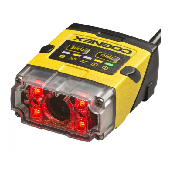
Getting Started Reader Layout The following images shows the built-in lighting system and other features of the DataMan 150. Illumination LEDs LED aimers 3-4* Mounting holes (M3 x 3.5mm) Trigger button Power indicator Train status/ Trigger status indicator Good/bad read... -
Page 17: Dimensions
Getting Started Dimensions The DataMan 150 consists of three main parts: 1. Optics module (lens including lens mount, illumination and front cover including filter mounting option for a Diameter (Ø): 12.3mm<Ø<12.7mm, Thickness (t): 1.6mm<t<2mm filter) 2. Main module, including sensor and CPU... - Page 18 Getting Started The size of the DataMan 150 in the straight configuration is shown in the following figure: The size of the DataMan 150 in the angled configuration is shown in the following figure:...
- Page 19 Getting Started...
-
Page 20: Setting Up Your Dataman 150
Setting Up Your DataMan 150 This section provides information on the physical appearance of the DataMan 150 reader. It also details the steps of mounting the reader, installing the lenses and filters of the reader, describes tuning, and gives information on the imager itself. -
Page 21: Changing From A 6.2 Mm Lens To A 16 Mm Lens
Changing from a 6.2 mm Lens to a 16 mm Lens Perform the following steps to change a 6.2 mm lens to a 16 mm lens on your DataMan 150 reader. Note: Disconnect the DataMan 150 reader from power before changing lenses. - Page 22 Setting Up Your DataMan 150 4. Attach the 16 mm lens mount. 5. Fasten the two M2x5mm Phillips head screws to 0.06 Nm using a torque wrench. 6. In the case of a manual focus lens, press the 16 mm lens cap onto the lens. The lens has 12 cutouts so it can be locked in steps of 30 degrees.
- Page 23 Setting Up Your DataMan 150 8. Attach the front cover. Observing the tightening sequence below, tighten all four M2x25 Phillips Pan head screws to 9 Ncm using a torque wrench. Note: The rib in the front cover must be oriented to the top side.
-
Page 24: Changing To An Illumination With A Different Color
Changing to an Illumination with a Different Color Perform the following steps to change the illumination. Note: Disconnect the DataMan 150 reader from power before changing to an illumination with a different color. 1. Remove the front cover: unscrew the four screws and take off the LED cover. -
Page 25: Installing An Optical Filter
Note: The rib in the front cover must be oriented to the top side. Installing an Optical Filter Perform the following steps to install an optical filter in the optics module of the DataMan 150 reader. Note: Disconnect the DataMan 150 reader from power before installing an optical filter. - Page 26 Setting Up Your DataMan 150 2. Insert the filter at the bottom side of the round opening in the transparent plastic part. 3. Push the top side of the filter firmly until it is sitting flat against the PCB. Note: Use finger to push the filter in and then a q-tip to clean the filter, or use a q-tip to push the filter into place.
-
Page 27: Installing A Liquid Lens
Setting Up Your DataMan 150 Installing a Liquid Lens Perform the following steps to install a liquid lens on your DataMan 150 reader. Note: Disconnect the DataMan 150 reader from power before installing the liquid lens. 1. Remove the front cover: unscrew the four M2x12mm Phillips Pan screws and take off the LED cover. - Page 28 Note: The rib in the front cover must be oriented to the top side. Note: The DataMan 150 liquid lens must be calibrated after field exchange. This can be done under Focus Settings in the DataMan Setup Tool. For more information, see the DataMan Questions and Answers...
-
Page 29: Field Of View And Reading Distances
7 MIL 5 MIL The following maps show the FoV of the DataMan 150 readers with a 6.2 mm lens. The horizontal and vertical field of view is shown for working distances of 40 mm, 65 mm and 105 mm. - Page 30 30 MIL The following maps show the FoV of the DataMan 150 readers with a 6.2 mm lens. The horizontal and vertical field of view is shown for working distances of 150 mm, 190 mm, 225 mm, 375 mm and 500 mm.
- Page 31 Setting Up Your DataMan 150 DM150 + 6.2 mm Lens DM152 + 6.2 mm Lens...
-
Page 32: Dataman 150 Readers With A 16 Mm Lens
15 MIL The following maps show the FoV of the DataMan 150 readers with a 16 mm lens. The horizontal and vertical field of view is shown for working distances of 80 mm, 150 mm, 225 mm, 375 mm, 500 mm and 1000 mm. -
Page 33: Tuning
DataMan 152 with a 16 mm Lens Tuning By tuning, your DataMan 150 reader automatically selects the best settings for the given reading situation, based on parameters of illumination, camera and decoder properties, and focal distance. Tuning autodiscriminates all enabled symbologies (both 1-D and 2-D). -
Page 34: Dataman 150 Specifications
Setting Up Your DataMan 150 DataMan 150 Specifications 128 g Weight Operating 0ºC — 40ºC (32ºF — 104ºF) Temperature Storage -10ºC — 60ºC (-14ºF — 140ºF) Temperature Maximum <95% (non-condensing) Humidity Environmental IP65 IEC 60068-2-27: 1000 shocks, semi-sinusoidal, 11g, 10ms... -
Page 35: Illumination Options
Setting Up Your DataMan 150 Illumination Options Illumination USB Powered PoE Powered 24V Externally Powered Board Max. exposure Max. duty Max. exposure Max. duty Max. exposure Max. duty time cycle time cycle time cycle Standard Red 500 µs 500 µs 1 ms High Power 500 µs... -
Page 36: Using Your Dataman 150
6. Select the device from the Network list (Discovered Devices) and click Connect. Setting the Focus Position DataMan 150 can operate in one of three distance ranges. Follow the steps below to set the focus position. 1. Remove the screws and the front cover. - Page 37 2. Using a flathead screwdriver, set the focus position from the front. Always turn clockwise to focus to a larger distance and counterclockwise to focus to a shorter distance. Note: If an optical filter has been mounted, first disconnect the DataMan 150 reader from power and remove the illumination module with the filter before adjusting the focus.
-
Page 38: External Triggering And Trigger Modes
Using Your DataMan 150 External Triggering and Trigger Modes If you are using external triggering, you can use any of the following methods to trigger your DataMan 150 reader: 1. Press the Trigger button ( ) on the reader. 2. Send a pulse on Input-0 line. -
Page 39: Incremental Training For Multiple Symbologies
DataMan 150 reports the status of the training and brightness optimization operations using its signaling LEDs. The second LED from left on the reader flashes green to indicate that the reader is currently trained, or yellow to indicate that it is not trained. - Page 40 Using Your DataMan 150 With incremental training enabled, you can train the reader using multiple images showing the symbologies you expect to decode. The reader will train each new symbology while retaining the existing trained symbologies.
-
Page 41: Connections, Optics And Lighting
Connections, Optics and Lighting Connections, Optics and Lighting This part contains descriptions about the I/O Cables, RS-232 cable, flying leads cable, USB connections, digital input and output wiring, and multi- port connections. Acquisition Triggering To trigger from an NPN (pull-down) type photo-detector or PLC output, connect to +24V and connect Into the output of the detector. - Page 42 Connections, Optics and Lighting White/Black Input-1 Light Blue/Black Output-1 Light Blue/Yellow Output-Common Light Blue/Green Input-Common...
-
Page 43: Flying Leads Cable
Connections, Optics and Lighting Flying Leads Cable You can connect a cable with flying leads (DM50-PWRIO-05) to the cable that is attached to the device. The following table shows the pinout and color description of the flying leads. Color Signal Green Green/Black Brown/White... -
Page 44: Wiring The Basic I/O Module
Wiring the Basic I/O Module Wiring the Basic I/O Module 1. Power: 5-24 VDC, 2.5W peak. Connect either ground pin to chassis ground. 2. Discrete output: Opto-isolated, current source or sink, depending on wiring; must connect logical ground to common. Outputs are opto-isolated and protected against reverse polarity. Max current 50 mA @ 24 VDC. Output 1 used for external illumination control by default. -
Page 45: Input Wiring Example
Wiring the Basic I/O Module Input Wiring Example... -
Page 46: Digital Input Wiring Diagrams
Digital Input Wiring Diagrams Digital Input Wiring Diagrams Current Sink Configuration Current Source Configuration Load to a TTL Buffer... -
Page 47: Pnp Configuration
Digital Input Wiring Diagrams PNP Configuration NPN Configuration... -
Page 48: Digital Output Wiring Diagrams
Digital Output Wiring Diagrams Digital Output Wiring Diagrams The digital outputs can be used as either NPN (pull-down) or PNP (pull-up) lines. For NPN lines, the external load should be connected between the output and the positive supply voltage (<26V). The outputs pull down to less than 3V when ON, which causes current to flow through the load. - Page 49 Digital Output Wiring Diagrams...
-
Page 50: Multi-Port Connections
You must construct your own cable that meets the requirements of your system configuration. The cable must provide a DB-15 connector for each DataMan 150 and a DB-9 connector for the PC serial port. Each DB- 15 connector must provide Tx Data, Rx Data, Trigger (Input 0), ground, and DC power. The Tx Data and Rx Data pins on adjacent connectors must be connected to provide the multi-port connection. - Page 51 15 meters. There is no fixed limit to the number of DataMan 150 readers that you can connect to a single PC. Each reader introduces a delay of about 100 ms when it retransmits received serial data. If you have 5 readers, this means that there will be a 400 ms delay between the time the first reader in the chain transmits data and the PC receives Each DataMan 150 reader must receive a hardware trigger signal on its Input 0 line.
-
Page 52: Precautions
Precautions Precautions Observe these precautions when installing the Cognex product, to reduce the risk of injury or equipment damage: This device requires the use of an LPS or NEC class 2 power supply. Do not connect or disconnect this device from the I/O module or 15-pin USB adapter cable while the I/O module or adapter cable is connected to a PC . -
Page 53: Regulations/Conformity
Regulations/Conformity Regulations/Conformity The DataMan 150 has Regulatory Model 1AA3 and meets or exceeds the requirements of all applicable standards organizations for safe operation. However, as with any electrical equipment, the best way to ensure safe operation is to operate them according to the agency guidelines that follow. Please read these guidelines carefully before using your device. - Page 54 Regulations/Conformity In order to avoid the dissemination of those substances in our environment and to diminish the pressure on the natural resources, we encourage you to use the appropriate take-back systems for product disposal. Those systems will reuse or recycle most of the materials of the product you are disposing in a sound way. The crossed out wheeled bin symbol informs you that the product should not be disposed of along with municipal waste and invites you to use the appropriate separate take-back systems for product disposal.
Need help?
Do you have a question about the DataMan 150 and is the answer not in the manual?
Questions and answers