
Related Manuals for Cognex DataMan 50 Series


Summary of Contents for Cognex DataMan 50 Series
- Page 1 ® DataMan Fixed-Mount Readers Reference Manual 2019 November 15 Revision: 6.1.6SR2.2...
-
Page 2: Legal Notices
Copyright © 2019. Cognex Corporation. All Rights Reserved. Portions of the hardware and software provided by Cognex may be covered by one or more U.S. and foreign patents, as well as pending U.S. and foreign patents listed on the Cognex web site at: cognex.com/patents. -
Page 3: Table Of Contents
Table of Contents Table of Contents Legal Notices Table of Contents About This Manual Symbols Safety Information Warnings And Notices Mechanical Information DataMan 50 Reader Dimensions DataMan 60 Reader Dimensions DataMan 70 Series Reader Dimensions DataMan 150 Reader Dimensions DataMan 260 Reader Dimensions DataMan 300 Series Reader Dimensions DataMan 360 Series Reader Dimensions DataMan 370 Series Reader Dimensions... - Page 4 Table of Contents DataMan 50 and 60 USB & Flying Leads I/O Cable DataMan 50 and 60 RS-232 & Flying Leads I/O Cable DataMan 50 and 60 Flying Leads Cable DataMan 50 and 60 Digital Input Lines DataMan 50 and 60 External Wiring Examples: Digital Input Lines DataMan 50 and 60 Digital Output Lines DataMan 50 and 60 External Wiring Examples: Digital Output Lines DataMan 70 15 Pin Adapter Cable...
- Page 5 Table of Contents Optics and Lighting DataMan 50 and 60 Reading Distances and Field of View DataMan 70, 150 and 260 Reading Distances and Field of View DataMan 300 and 360 Series Readers Reading Distances and Field of View Scan Map for DataMan 300 and 360 Series Readers Using a 10.3 mm Lens Scan Map for DataMan 300 and 360 Series Readers Using a 16 mm Lens Scan Map for DataMan 300 and 360 Series Readers Using a 19 mm Lens Scan Map for DataMan 300 and 360 Series Readers Using a 24 mm Lens with Liquid Lens...
- Page 6 Table of Contents Code Training Automatic Code Training for DPM Symbols Image Buffering and Image Recording Retrieving Buffered Images DataMan Multi-Reader Sync Configuration Primary Reader Secondary Readers Data Formatting Limitations Synchronized Acquisition Using C/CS-Mount Lenses Aperture Setting Selecting Optimum Focus Optimizing Performance Read Interval and Timeout Configuration Optimizing Burst Trigger Parameters...
-
Page 7: About This Manual
About This Manual About This Manual The DataMan Fixed-Mount Readers Reference provides detailed information on the configuration and operation of DataMan fixed-mount readers. It includes the following sections: Safety Information Mechanical Information Electrical Information Optics and Lighting Operation Application Guide Symbols The following symbols indicate safety precautions and supplemental information: WARNING:... -
Page 8: Safety Information
Use of controls or adjustments or performance of procedures other than those specified herein may result in hazardous radiation exposure. Do not attempt to service or repair this product - return it to Cognex for service. Do not permit anyone other than Cognex Corporation to service, repair, or adjust this product. -
Page 9: Mechanical Information
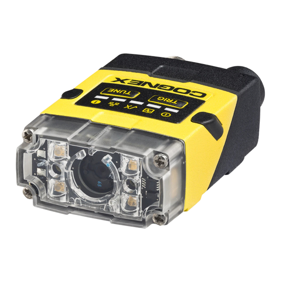
Mechanical Information Mechanical Information This section provides information on various mechanical features of the DataMan 50, DataMan 60, DataMan 70, DataMan 150, DataMan 260, DataMan 300, DataMan 360, DataMan 470, and DataMan 503 series readers, such as dimensions, lens replacement, mounting information, as well as thermal and environmental requirements. DataMan 50 Reader Dimensions... -
Page 10: Dataman 60 Reader Dimensions
Mechanical Information DataMan 60 Reader Dimensions... -
Page 11: Dataman 70 Series Reader Dimensions
Mechanical Information DataMan 70 Series Reader Dimensions... -
Page 12: Dataman 150 Reader Dimensions
Mechanical Information DataMan 150 Reader Dimensions DataMan 150 dimensions in the straight configuration: DataMan 150 dimensions in the angled configuration:... -
Page 13: Dataman 260 Reader Dimensions
Mechanical Information DataMan 260 Reader Dimensions DataMan 260 dimensions in the straight configuration: DataMan 260 dimensions in the angled configuration:... -
Page 14: Dataman 300 Series Reader Dimensions
Mechanical Information DataMan 300 Series Reader Dimensions M3-5 (4x) mounting holes of the device M3-6 (4x) mounting holes for external illumination Illumination lights Operating buttons S-Mount (M12) Lens version C-Mount Lens version... - Page 15 Mechanical Information...
-
Page 16: Dataman 360 Series Reader Dimensions
Mechanical Information DataMan 360 Series Reader Dimensions DataMan 360 dimensions without lens and with C-mount and S-mount lens options: M3-5 (4x) mounting holes of the device M3-6 (4x) mounting holes for external illumination Illumination lights Operating buttons C-Mount Lens version S-Mount (M12) Lens version... -
Page 17: Dataman 370 Series Reader Dimensions
Mechanical Information DataMan 370 Series Reader Dimensions DataMan 370 Series Reader with High Power Integrated Light (HPIL) -
Page 18: Dataman 370 Series Reader With High Power Illumination Accessory (Hpia)
Mechanical Information DataMan 370 Series Reader with High Power Illumination Accessory (HPIA) DataMan 370 Series Reader with High Power Integrated Torch (HPIT) -
Page 19: Dataman 470 Series Reader Dimensions
Mechanical Information DataMan 470 Series Reader Dimensions DataMan 470 Reader with High Power Integrated Light (HPIL) DataMan 470 Reader with High Power Illumination Accessory (HPIA) -
Page 20: Dataman 470 Reader With High Power Integrated Torch (Hpit)
Mechanical Information DataMan 470 Reader with High Power Integrated Torch (HPIT) -
Page 21: Dataman 503 Reader Dimensions
Mechanical Information DataMan 503 Reader Dimensions... -
Page 22: Service Procedures
Mechanical Information Service Procedures DataMan 50 Service Procedures DataMan 50 can operate in one of three distance ranges. Perform the following steps to set the focus position: 1. Remove the screws, washers, lens cover and rubber part. 2. Set focus by positioning a coin into the lens cap slit and turning the coin. Do not use a coin thicker than 2 mm. If no coin is available, use the edge of the back cover 3. - Page 23 Mechanical Information 6. Tighten screws in the order shown below. The maximum torque for the cover screws is 5 N-cm (0.4 pound-inch). The yellow arrow on the cover indicates the selected focus position.
-
Page 24: Dataman 60 Service Procedures
Mechanical Information DataMan 60 Service Procedures DataMan 60 can operate in one of three distance ranges. Perform the following steps to set the focus position: 1. Remove the lens cover. 2. Set the focus position to 45, 70, or 110: turn the lens cap clockwise (45->70->110) to focus to a larger distance; turn the lens cap counter-clockwise (110->70->45) to focus to a shorter distance. -
Page 25: Dataman 70 Service Procedures
Mechanical Information DataMan 70 Service Procedures DataMan 70 can operate in one of three distance ranges. Follow the steps below to set the focus position. 1. Remove the screws and the front cover. DM70 with 6.2 mm lens DM70 with 16 mm lens 2. - Page 26 Mechanical Information 3. Remount the front cover. Observing the tightening sequence below, tighten all four screws to 9 Ncm using a torque wrench. DM70 with 6.2 mm lens DM70 with 16 mm lens Note: The rib in the front cover must be oriented to the top side.
-
Page 27: Service Procedures
Mechanical Information Service Procedures DataMan 150 and 260 Series Service Procedures Setting the Focus Position of a DataMan 150 or DataMan 260 Reader DataMan 150 and 260 can operate in one of three distance ranges. Follow the steps below to set the focus position. Note: The following steps describe service procedures for both the DataMan 150 and the 260 readers, but the images show only the DataMan 260. - Page 28 Mechanical Information Changing from a 6.2 mm Lens to a 16 mm Lens on a DataMan 150 or DataMan 260 Reader Perform the following steps to change a 6.2 mm lens to a 16 mm lens on your DataMan 150 or 260 reader. Note: Disconnect the DataMan 150 or 260 reader from power before changing lenses.
- Page 29 Mechanical Information 6. In the case of a manual focus lens, press the 16 mm lens cap onto the lens. The lens has 12 cutouts so it can be locked in steps of 30 degrees. 7. Attach the illumination board. Note: Take care to attach the illumination with the right orientation.
- Page 30 Mechanical Information Note: The following steps describe service procedures for both the DataMan 150 and the 260 readers, but the images show only the DataMan 260. 1. Remove the front cover: unscrew the four M2x12 mm Phillips Pan head screws and take off the LED cover. 2.
- Page 31 Mechanical Information 4. Attach the front cover. Observing the tightening sequence below, tighten all four M2x12 mm Phillips Pan head screws to 9 Ncm using a torque wrench. Note: The rib in the front cover must be oriented to the top side. Installing a Liquid Lens Perform the following steps to install a liquid lens on your DataMan 150 or DataMan 260 reader.
- Page 32 Mechanical Information 1. Remove the front cover: unscrew the four M2x12 mm Phillips Pan screws and take off the LED cover. 2. Remove the illumination module. 3. Turn the lens cap to the 105 mm position. 4. Remove the lens cap from the imager lens by pulling it. Note: Do not rotate the imager lens while the lens cap is removed.
- Page 33 Mechanical Information 5. Attach the liquid lens accessory by aligning the 2x2 connectors of the liquid lens with the 2x2 sockets on the optics mount. 6. Press the liquid lens onto the imager lens until you reach the stop. 7. Reattach the illumination.
- Page 34 Mechanical Information 8. Attach the front cover. Observing the tightening sequence below, tighten all four M2x12 mm Phillips Pan screws to 9 Ncm using a torque wrench. Note: The rib in the front cover must be oriented to the top side. Note: The DataMan 150 and the DataMan 260 liquid lens must be calibrated after field exchange.
- Page 35 Mechanical Information 1. Remove the front cover: unscrew the four screws and take off the LED cover. 2. Remove the illumination module. 3. Attach a new color illumination module. Note: Make sure you attach the illumination with the right orientation.
- Page 36 Mechanical Information 4. Attach the front cover. Observing the tightening sequence below, tighten all four screws to 9 Ncm using a torque wrench. Note: The rib in the front cover must be oriented to the top side.
-
Page 37: Dataman 300 And 360 Series Service Procedures
Mechanical Information DataMan 300 and 360 Series Service Procedures Replacing a 10.3 mm Lens To remove and replace a 10.3 mm lens of a DataMan 300 or 360 series reader, perform the following steps: WARNING: Disconnect the DataMan reader from power before continuing. CAUTION: Do not leave the image sensor exposed to the environment. - Page 38 Mechanical Information 4. Loosen the lens locking ring and withdraw the module. When reinstalling the module, observe the following precautions: Make sure that the liquid lens cable is not pinched, pulled or crimped during installation. 5. Loosen the locking ring and withdraw the lens. When reattaching the front cover, tighten the screws in the sequence shown below and observe a torque limit of 9 N-cm (0.8 Lb-In).
- Page 39 Mechanical Information 1. Attach the 24 mm Lens to the device by using the screw thread on the metal ring. 1. Insert the Liquid Lens cable into the connector of the device. 2. Attach the Liquid Lens to the front side of the 24mm Lens.
- Page 40 Mechanical Information 3. Place the DM360-HPIL-RE-01 or DM360-HPIL-RE-P-01 unit on the front of the device. CUSTOMIZED CAPTIVE SCREW, PHILLIPS PAN HEAD, M3x28mm Note: The minimum peak current capacity of the power supply for the device and the DM360-HPIL-RE-01 / DM360-HPIL-RE-P-01 is 2 A per unit for the DataMan 300 and 2.2 A per unit for the DataMan 360. Note: The DM360-HPIL-RE-01 or DM360-HPIL-RE-P-01 is also compatible with the 10.3 mm Liquid Lens.
- Page 41 Mechanical Information 1. Remove and retain the four screws at the corners of the front cover. 2. Remove the front cover. 3. Remove the rubber lens-locking cone from the lens. 4. Remove the lens. When replacing the lens, observe the following precaution: Avoid rotating the lens when you insert it.
- Page 42 Mechanical Information Replacing a C-Mount Lens To remove and replace a C-Mount lens of a DataMan 300 or 360 series reader, perform the following steps: WARNING: Disconnect the DataMan reader from power before continuing. CAUTION: Do not leave the image sensor exposed to the environment. Note: The following steps describe service procedures for both the DataMan 300 and the 360 readers, but the images show only the DataMan 360.
-
Page 43: Dataman 370 And 470 Series Service Procedures
370 Series Reference Manual and the DataMan 470 Series Reference Manual, respectively. Tools needed: Wrench for lens locking ring (10.3 mm LL only - delivered by Cognex with Liquid Lens module) Phillips screwdriver To install a 10.3 mm or a 24 mm liquid lens module of a DataMan 374 or 474 reader, perform the following steps: WARNING: Disconnect the DataMan reader from power before continuing. - Page 44 Mechanical Information Note: The following steps describe service procedures for both the DataMan 374 and the 474 readers, but the images show only the DataMan 374. 1. Remove the adhesive protective film covering the threaded lens opening. 2. Attach the 24 mm Lens to the device by using the screw thread on the metal ring. Insert an S-Mount adapter, thread the 10.3 mm Lens into the reader, and tighten the locking ring.
- Page 45 Mechanical Information 3. Insert the Liquid Lens cable into the connector of the reader. WARNING: To avoid equipment damage, the cables must be routed as shown in the figure. 4. Attach the Liquid Lens to the front side of the 24 mm Lens. In case of the 10.3 mm Lens, attach the liquid lens module onto the nose of the lens.
- Page 46 Mechanical Information 5. Place the HPIL unit on the front of the device. CUSTOMIZED CAPTIVE SCREW, PHILLIPS PAN HEAD, M3x28 mm 6. Screw in the four screws. Note: Use 0.2 Nm torque on the screws and tighten in sequence. Replacing a 10.3 mm Lens To remove and replace a 10.3 mm lens of a DataMan 370 or 470 series reader, perform the following steps: WARNING: Disconnect the DataMan reader from power before continuing.
- Page 47 For a list of lenses compatible with the HPIA, see the DataMan 370 Series Reference Manual and the DataMan 470 Series Reference Manual, respectively. Tools needed: Wrench for lens locking ring (10.3 mm LL only - delivered by Cognex with Liquid Lens module) Phillips screwdriver (PH0) Phillips screwdriver (PH1) Note: The following steps describe service procedures for both the DataMan 370 and the 470 series readers, but the images show only the DataMan 370.
- Page 48 Mechanical Information 2. Place the HPIA on the front of the reader. 3. Insert the lens cover mounting plate into the HPIA and secure them to the reader using the four M3 screws. M3 x 16 mm screws Note: Use a 3 mm hex wrench to torque the screws to 0.34 Nm (3 in-lb). Tighten in sequence.
- Page 49 Mechanical Information 4. Attach the C-mount lens cover to the front of the plate and secure it using the four M2 screws. Note: For lenses that do not fit under the DM500-CMTLC-000 lens cover, you are required to use the DM500-LNSEXT-000 lens cover extension.
- Page 50 Mechanical Information 3. Attach the DM470 HPIT adapter plate. M3 x 6 mm screws Note: Use a 2 mm hex wrench to torque the screws to 0.34 Nm (3 in-lb). Tighten in sequence. 4. Attach the lens module and fix the lens with the captive screws. Note: Use a Phillips screwdriver (PH0) to torque the screws to 0,08 Nm (0.7 in-lb).
- Page 51 Mechanical Information M3 x 6.35 mm captive screws Note: Use a 2 mm hex wrench to torque the captive screws to 0.34 Nm (3 in-lb). Tighten in sequence. 6. Attach the front cover. M3 x 12mm captive screws Note: Use a Phillips Screwdriver (PH0) to torque the captive screws to 0.31 Nm (2.75 in-lb). Tighten in sequence.
- Page 52 Mechanical Information Possible hardware configurations using a C-Mount lens with a DataMan 370 or 470 series reader: C-Mount Cover System Lens Lens Part Number Short C-Mount Cover (DM300-CMCOV) (DM300-CMCOV-SH) DM370 12 mm F8 LEC-CFF12-F8 DM470 16 mm F8 LEC-CFF16-F8 25 mm F8 LEC-CFF25-F8 35 mm F8 LEC-CFF35-F8...
- Page 53 Mechanical Information d. Adjust focus for maximum sharpness. Enhance image quality in the DataMan Setup Tool for better guidance. 4. Attach the C-Mount cover base.
- Page 54 Mechanical Information 5. Add the screws to the C-Mount cover base. PHILLIPS PAN HEAD M2 X 6 mm Note: Tighten in sequence. Torque limit: 9 Ncm (0.8 in-lbs). 6. Attach the front cover. Note: Do not unscrew the front-most part of the nose of the cover to avoid risking the glass lens falling out. 7.
- Page 55 Mechanical Information Replacing a C-Mount Lens To remove and replace a C-Mount lens of a DataMan 370 or 470 series reader, perform the following steps: WARNING: Disconnect the DataMan reader from power before continuing. CAUTION: Do not leave the image sensor exposed to the environment. Note: The following steps describe service procedures for both the DataMan 370 and the 470 series readers, but the images show only the DataMan 470.
-
Page 56: Dataman 503 Service Procedures
Mechanical Information DataMan 503 Service Procedures Installing a C-Mount Lens DataMan 503 ships with no lens installed. You must install a standard C-mount lens before using your reader. For reading distances and field of view charts, see the DataMan Fixed-Mount Reference, available through the Windows Start menu or the DataMan Setup Tool Help menu. -
Page 57: Maintenance
Mechanical Information 4. Lock the cover in place. Maintenance Replacing the SD Card The DataMan 370 and 470 series readers are equipped with a Micro SD card slot and an SD card is pre-installed for saving backup and configuration files. In the unlikely event when a reader breaks down and needs to be replaced, complete the following steps to clone the reader by replacing the SD card. - Page 58 Mechanical Information 5. Replace the SD card cover and reinsert the screw(s). Note: Torque the screw(s) to 0.18 Nm (25 in-oz). Tighten in sequence. DataMan 370 DataMan 470 6. Restore power to the reader.
-
Page 59: Mounting Requirements
Mechanical Information Mounting Requirements The DataMan 150, 260, 300, 360, 370, 470, and 503 series readers provide four threaded attachment points, located as shown in the previous sections: DataMan 70 Series Reader Dimensions DataMan 150 Series Reader Dimensions DataMan 260 Series Reader Dimensions DataMan 300 Series Reader Dimensions DataMan 360 Series Reader Dimensions DataMan 370 Series Reader Dimensions... -
Page 60: Mounting Your Dataman 150 And 260 Reader
Mechanical Information Fastener: 2 x DIN 7985 M3x30 mm or DIN 912/ISO 4762 M3x30 mm Nut: 2 x DIN 985 M3 Mounting Your DataMan 150 and 260 Reader Mounting the DataMan 150 and the DataMan 260 at a slight angle (15°) can reduce reflections and improve reader performance. - Page 61 Mechanical Information Right-Angle Configuration Changing Orientation Perform the following steps to change between in-line and right-angle configuration. Note: Switching between in-line and right-angle configuration is recommended only up to 10 times in the lifetime of your DataMan device. Disconnect the DataMan device from power before changing the orientation. WARNING: Make sure that no electrostatic charges are applied to the PCB.
- Page 62 Mechanical Information 1. Carefully remove the screw covers, threaded nuts and washers. DataMan 150 DataMan 260 M2 Torx 10 CAP NUT DIN 6798A M2 LOCKWASHER 2. Detach the main module and the I/O connector module by firmly pulling them apart. DataMan 150 DataMan 260 3.
- Page 63 Mechanical Information Note: The flat side of the gasket (marked as "Front" in the image above) has to face outside. WARNING: Do not touch any electrical component. 3. Reattach the I/O connector module to the main module. DataMan 150 DataMan 260 4.
-
Page 64: Mounting Your Dataman 370 And 470 Reader
Mechanical Information 5. After each cap nut has been fastened, torque to 0.12 Nm (1.06 in-lb) and reinstall the screw covers. Note: There are unique left and right screw covers. Take care to attach them correctly. DataMan 150 DataMan 260 Mounting Your DataMan 370 and 470 Reader The accessory mounting bracket kit (DMBK-370-MNT for the DataMan 370 and DMBK-470-MNT for the DataMan 470) includes the mounting bracket, four Phillips flat head M3 DIN 965 screws for attaching the reader to the mounting bracket... - Page 65 Mechanical Information 1. Align the holes on the mounting surface with the mounting holes on the reader. DataMan 370 DataMan 470 2. Insert the M3x5, DIN 965 (4x) screws into the mounting holes. Note: Use a 2.5 mm hex wrench to torque the captive screws to 0.60 Nm (5 in-lb). Tighten in sequence. DataMan 370 DataMan 470 3.
- Page 66 Mechanical Information 4. Attach the mounting bracket to the mounting surface using M6, DIN 912 (ISO 4762) socket head screws with M6 drop-in nuts for OTS aluminum profiles. Mounting the DataMan reader at a slight angle (15°) can reduce reflections and improve performance. DataMan 370 DataMan 470...
-
Page 67: Grounding
If you want to mount your reader to an electrically isolated bracket, the reader needs to be individually grounded. For this purpose, Cognex recommends that you connect at least one of the 4 mounting holes on the bottom of the device with a minimum 22 gauge grounding wire to system ground (PE). -
Page 68: Thermal And Environmental Requirements
Mechanical Information Thermal and Environmental Requirements See the following table for thermal and environmental requirements: Operating temperature 0 ºC — 40 ºC (32 ºF — 104 ºF) Storage temperature -10 ºC — 60 ºC (-14 ºF — 140 ºF) Maximum humidity 95% (non-condensing) DataMan 50, 150, 260, 300, 360, and 503 IP Rating The DataMan 50, 150, 260, 300, 360 series and 503 readers provide IP65 protection against dust and water intrusion. - Page 69 Mechanical Information All connectors must have cables connected or be sealed with protective plugs. The reader front cover and lens cover must be correctly installed. The requirements for temperature, vibration, and shock must be met.
-
Page 70: Electrical Information
Electrical Information Electrical Information DataMan 50 and 60 Discrete I/O Connector The I/O cable provides access to trigger and high-speed outputs. Unused wires can be clipped short or tied back using a tie made of non-conductive material. For RS-232, use the Power Supply return path for ground. Note: GND (Pin 4) is connected to the reader housing, cable shield, and DB15 shell. -
Page 71: Dataman 50 And 60 Rs-232 & Flying Leads I/O Cable
Electrical Information DataMan 50 and 60 RS-232 & Flying Leads I/O Cable You can connect a cable with RS-232 & flying leads (DM-RS232IO-00) to the cable that is attached to the device. The following table shows the pinout and color description of the flying leads. Color Signal Black... -
Page 72: Dataman 50 And 60 Digital Input Lines
Electrical Information DataMan 50 and 60 Digital Input Lines Inputs are not galvanic isolated but need to be referenced to ground. -
Page 73: Dataman 50 And 60 External Wiring Examples: Digital Input Lines
Electrical Information DataMan 50 and 60 External Wiring Examples: Digital Input Lines The following figures show external wiring examples for digital input lines for the DataMan 50. The DataMan 60 has the same characteristics. -
Page 74: Dataman 50 And 60 Digital Output Lines
Electrical Information DataMan 50 and 60 Digital Output Lines The digital outputs can be used as either NPN (pull-down) or PNP (pull-up) lines. For NPN lines, the external load should be connected between the output and the positive supply voltage (<26 V). The outputs pull down to less than 3 V when ON, which causes current to flow through the load. -
Page 75: Dataman 50 And 60 External Wiring Examples: Digital Output Lines
Electrical Information DataMan 50 and 60 External Wiring Examples: Digital Output Lines The following figures show external wiring examples for digital input lines for the DataMan 50. The DataMan 60 has the same characteristics. -
Page 76: Dataman 70 15 Pin Adapter Cable
Electrical Information DataMan 70 15 Pin Adapter Cable P1 Pin Number Signal Name Reserved Reserved Reserved Reserved Reserved Ground Reserved Reserved Adapter Power External Trigger External Illumination... -
Page 77: Dataman 70 9 Pin Adapter Cable
Electrical Information DataMan 70 9 Pin Adapter Cable The following table shows the pinouts. Pin Number Signal Name Trigger TXD Output TTL Only RXD Input TTL Only Ground +5 V Power CTS Input TTL Only RTS Output TTL Only Beeper/Download... -
Page 78: Dataman 70 Serial Io Adapter (Dma-Serialrest-St)
Electrical Information DataMan 70 Serial IO Adapter (DMA-SERIALREST-ST) This is a male connector/plug. Pin Number Signal Name Reserved DC+ (system power, 5-24 VDC) Output-0 Input-0 Output-Common Reserved Reserved DataMan 150 USB Cable The DataMan 150 is available with USB and RS-232 communication options. The I/O module with USB has all signals on a SUB-D 15 connector with the following pinouts: Color Signal... - Page 79 Electrical Information Color Signal Green/Black RxD (RS-232) Red & Red/Black Brown/White DC+ (system power, 5-24 VDC) Blue Blue/White Output-0 White Input-0 White/Black Input-1 Light Blue Light Blue/Black Output-1 Light Blue/Yellow Output-Common Light Blue/Green Input-Common Yellow Reserved Yellow/Black Reserved Note: Pin numbers are shown for cable connector, not I/O module.
-
Page 80: Dataman 70 And 150 Discrete I/O Connector
Electrical Information DataMan 70 and 150 Discrete I/O Connector You can connect a cable with USB & flying leads (DM-USBIO-00) to the cable that is attached to the device. The following table shows the pinout and color description of the flying leads. Note: GND (Pin 4) is connected to the reader housing, cable shield, and DB15 shell. -
Page 81: Dataman 150 Flying Leads Cable
Electrical Information DataMan 150 Flying Leads Cable You can connect a cable with flying leads (DM50-PWRIO-05) to the cable that is attached to the device. The following table shows the pinout and color description of the flying leads. Color Signal Green Green/Black Brown/White... -
Page 82: Dataman 150 Rs-232 Connections
Electrical Information Note: The DataMan PC software must be installed for this connection type. DataMan 150 RS-232 Connections You can connect the DataMan 150 reader to a PC or other device over a standard RS-232 serial connection. Note: You must supply external power to use this connection type. You can make a connection in the following ways: Connect directly to the PC: Connect to the PC through a basic I/O module:... -
Page 83: Output Wiring Example
Electrical Information 1. Power: 5-24 VDC, 2.5 W peak. Connect either ground pin to chassis ground. 2. Discrete output: Opto-isolated, current source or sink, depending on wiring; must connect logical ground to common. Outputs are opto-isolated and protected against reverse polarity. Max current is 50 mA @ 24 VDC. Output 1 is used for external illumination control by default. -
Page 84: Input Wiring Example
Electrical Information Input Wiring Example DataMan 150 Digital Input Wiring Diagrams Current Sink Configuration Current Source Configuration... -
Page 85: Pnp Configuration
Electrical Information PNP Configuration NPN Configuration Dataman 150 Digital Output Wiring Diagrams The digital outputs can be used as either NPN (pull-down) or PNP (pull-up) lines. For NPN lines, the external load should be connected between the output and the positive supply voltage (<26 V). The outputs pull down to less than 3 V when ON, which causes current to flow through the load. -
Page 86: Sinking Outputs, Sourcing Inputs
Electrical Information Sinking Outputs, Sourcing Inputs Sinking Outputs, Sinking Inputs... -
Page 87: Electrical Information
Electrical Information Electrical Information DataMan 260 Discrete I/O Connector The I/O breakout cable (CCBL-05-01) provides access to trigger and high-speed outputs. You can clip unused wires short or use a tie made of non-conductive material to tie them back. For RS-232, use the Power Supply return path for ground. -
Page 88: Dataman 260 Ethernet Cable
Electrical Information Signal: PoE Ethernet Model DataMan 260 Ethernet Cable The Ethernet cable (CCB-84901-2001-05) provides Ethernet connection for network communications. The Ethernet cable can be connected to a single device or provide connections to multiple devices via a network switch or router. Note: Cables are sold separately.The wiring for this cable follows standard industrial Ethernet M12 specifications. -
Page 89: Dataman 150 And 260 Acquisition Triggering
Electrical Information X-coded to RJ45 Cable P1 Pin Number Wire Color Signal Name P2 Pin Number White/Orange TxRx A + Orange TxRx A - White/Green TxRx B + Blue TxRx C + White/Blue TxRx C - Green TxRx B - White/Brown TxRx D + Brown... -
Page 90: Dataman 260 High-Speed Output Lines
Electrical Information DataMan 260 High-Speed Output Lines The high-speed outputs can be used as either NPN (pull-down) or PNP (pull-up) lines. Specification Description Voltage 28 V maximum through external load 50 mA maximum sink current Current OFF state leakage current 100 µA External load resistance 240 Ohms to 10K Ohms Each line rated at a maximum 50 mA, protected against over-current, short circuits and transients from switching inductive loads. -
Page 91: Dataman 300 5M Rs-232 Connection Cable (Ccb-M12Xdb9Y-05)
Electrical Information To connect to a PNP-compatible PLC input, connect Output 0, Output 1, Output 2 or Output 3 directly to the PLC input. When enabled, the output pulls the PLC input up to greater than 21 VDC. To connect the high-speed outputs to a relay, LED or similar load, connect the negative side of the load to the output and the positive side to +24 VDC. -
Page 92: Dataman 300, 360, 370, And 470 Series Readers Discrete I/O Connector
Electrical Information DataMan 300, 360, 370, and 470 Series Readers Discrete I/O Connector The Breakout cable provides access to trigger and high-speed outputs. You can clip unused wires short or use a tie made of non-conductive material to tie them back. For RS-232, use the Power Supply return path for ground. 5m Breakout Cable (CCBL-05-01) The figure on the left shows the plug on the device. -
Page 93: Breakout Cable (Ccb-M12X12Fy-Xx)
Electrical Information 5m Breakout Cable (CCB-M12x12Fy-xx) The figure on the left shows the plug on the device. -
Page 94: Breakout Cable (Ccb-Pwrio-Xx)
Electrical Information 15m Breakout Cable (CCB-PWRIO-XX) The figure on the left shows the plug on the device. -
Page 95: Dataman 300, 360, 370, And 470 Series Readers External Light Control
Electrical Information DataMan 300, 360, 370, and 470 Series Readers External Light Control The External Light cable is used to connect to an external lighting device, providing power and strobe control. A 4-pin cable is provided for the external light control. The drawing on the left shows the socket on the device. This socket does not work if the external light is connected to one of the outputs on the breakout cable. -
Page 96: Dataman 300, 360, 370, And 470 Series, And Dataman 503 Readers High-Speed Output Lines
Electrical Information The DataMan 300, 360, 370, and 470 series readers support 26.4 V maximum across input pins – Transition approximately 12 V (Min.). The DataMan 503 reader supports 28 V maximum across input pins - Transition approximately 12 V (Min.). DataMan 300, 360, 370, and 470 Series, and DataMan 503 Readers High-Speed Output Lines The high-speed outputs can be used as either NPN (pull-down) or PNP (pull-up) lines. - Page 97 Electrical Information...
-
Page 98: Dataman 300, 360, 370, And 470 Series Readers High-Speed Output Wiring
Electrical Information DataMan 300, 360, 370, and 470 Series Readers High-Speed Output Wiring To connect to an NPN-compatible PLC input, connect Output 0, Output 1, Output 2, or Output 3 directly to the PLC input. When enabled, the output pulls the PLC input down to less than 3 VDC. To connect to a PNP-compatible PLC input, connect Output 0, Output 1, Output 2 or Output 3 directly to the PLC input. -
Page 99: Dataman 300 And 503 Ethernet M12 To Rj45 Cable (Ccb-84901-Y00X-Xx)
Electrical Information DataMan 300 and 503 Ethernet M12 to RJ45 Cable (CCB-84901- y00x-xx) The Ethernet cable provides Ethernet connection for network communications. The Ethernet cable can be connected to a single device or provide connections to multiple devices via a network switch or router. P1 Pin# Signal Name Wire Color... -
Page 100: Dataman 503 Discrete I/O Connector
Electrical Information DataMan 503 Discrete I/O Connector 5 m Breakout Cable (CCBL-05-01) The Breakout cable provides access to trigger and high-speed outputs.You can clip unused wires short or use a tie made of non-conductive material to tie them back. The figure on the left shows the plug on the device. DataMan 503 RS-232 Serial Connector The RS-232 cable (CCB-M8X4.xx) provides an optional connection between the reader and your PC. -
Page 101: Dataman 503 External Light Control
Electrical Information DataMan 503 External Light Control A 4-pin cable (CCB-M12x4MS) is provided for the external light control. The drawing on the left shows the socket on the device. This socket does not work if the external light is connected to one of the outputs on the I/O cable. -
Page 102: Dataman 503 Power Requirements
Electrical Information To connect the high-speed outputs to a relay, LED or similar load, connect the negative side of the load to the output and the positive side to +24 VDC. When the output switches on, the negative side of the load is pulled down to less than 3 VDC, and 24 appears across the load. -
Page 103: Connecting The Encoder To A Dataman
Electrical Information Connecting the Encoder to a DataMan Encoder is supported on the following DataMan devices and with the following conditions: DM50, DM60, DM70, DM150 unidirectional One input counts encoder ticks • One input counts encoder ticks DM260, DM300, DM503 bidirectional •... -
Page 104: Optics And Lighting
Optics and Lighting Optics and Lighting This section contains information about the image formation components of the DataMan 50, 60, 70, 150, 260, 503 and DataMan 300, 360, 370, and 470 series readers. DataMan 50 and 60 Reading Distances and Field of View The following chart shows the horizontal field of view for the DataMan 50 and 60 at a range of working distances, together with the supported range of reading distances at 45 mm focus position. - Page 105 Optics and Lighting This chart shows the supported range of reading distances at 110 mm focus position. The following table shows the Field of View widths at various distances. Distances in mm DM50/DM60...
-
Page 106: Dataman 70, 150 And 260 Reading Distances And Field Of View
Optics and Lighting DataMan 70, 150 and 260 Reading Distances and Field of View DataMan 70, 150 and 260 Readers with a 6.2 mm Lens Short Range (Focused to 105 mm) The following tables show the field of view (FoV) widths of the 6.2 mm lens focused to 105 mm at various distances. DM70, DM150 or DM260 Distances in mm 2D min. - Page 107 Optics and Lighting DM72, DM152 or DM262 + 6.2 mm Lens Long Range (Focused to 190 mm) The following tables show the FoV widths of the 6.2 mm lens focused to 190 mm at various distances. DM150 or DM260 Distances in mm 2D min.
- Page 108 Optics and Lighting The following maps show the field of view (FoV) of the DataMan 150 or DataMan 260 readers with a 6.2 mm lens. The horizontal and vertical field of view is shown for working distances of 150 mm, 190 mm, 225 mm, 375 mm and 500 DM150 or DM260 + 6.2 mm Lens DM152 or DM262 + 6.2 mm Lens...
- Page 109 Optics and Lighting DataMan 150 or DataMan 260 Readers with a 16 mm Lens The following tables show the field of view (FoV) widths of the 16 mm lens at various distances. DM150 or DM260 Distances in mm 2D min. code 1D min.
- Page 110 Optics and Lighting DM152 or DM262 + 16 mm Lens...
-
Page 111: Dataman 300 And 360 Series Readers Reading Distances And Field Of View
Optics and Lighting DataMan 300 and 360 Series Readers Reading Distances and Field of View The DataMan 300 and 360 series readers: DataMan 300/360, DataMan 302/362, and DataMan 303/363 have different fields of view because of the different regions of the sensor used by each reader. Scan Map for DataMan 300 and 360 Series Readers Using a 10.3 mm Lens The map below shows the field of view of the DataMan 300/360, DataMan 302/362 and DataMan 303/363 readers with a 10.3 mm lens (with or without a liquid lens). -
Page 112: Scan Map For Dataman 300 And 360 Series Readers Using A 16 Mm Lens
Optics and Lighting Scan Map for DataMan 300 and 360 Series Readers Using a 16 mm Lens This map shows the field of view of the DataMan 300/360, DataMan 302/362 and DataMan 303/363 readers with a 16 mm lens. The FoV values are shown as follows: outer: DM302/362, DM303/363 inner: DM300/360 The reading distances for the DM300/360 and DM302/362 readers are the same. -
Page 113: Scan Map For Dataman 300 And 360 Series Readers Using A 19 Mm Lens
Optics and Lighting Scan Map for DataMan 300 and 360 Series Readers Using a 19 mm Lens This map shows the field of view of the DataMan 300/360, DataMan 302/362 and DataMan 303/363 readers with a 19 mm lens (with or without a liquid lens). The FoV values are shown as follows: outer: DM302/362, DM303/363 inner: DM300/360... -
Page 114: Scan Map For Dataman 300 And 360 Series Readers Using A 24 Mm Lens With Liquid Lens
Optics and Lighting Scan Map for DataMan 300 and 360 Series Readers Using a 24 mm Lens with Liquid Lens The maps in this section show the field of view of the DataMan 300/360, DataMan 302/362, and DataMan 303/363 readers with a 24 mm lens with a liquid lens and DM360-HPIL-RE-01 or DM360-HPIL-RE-P-01 cover. The FoV values are shown as follows: outer: DM303/DM363 middle: DM302/DM362... - Page 115 Optics and Lighting Scan Map for the DataMan 300 Series Readers with a 24 mm Lens with Liquid Lens...
-
Page 116: Scan Map For Dataman 300 And 360 Series Readers Using A 25 Mm Lens
Optics and Lighting Scan Map for the DataMan 360 Series Readers with a 24 mm Lens with Liquid Lens Scan Map for DataMan 300 and 360 Series Readers Using a 25 mm Lens This map shows the field of view of the DataMan 300/360, DataMan 302/362, and DataMan 303/363 readers with a 25 mm lens. -
Page 117: Dataman 370 Series Readers Reading Distances And Field Of View
Optics and Lighting The following table shows the Field of View widths in mm at various distances. Distances in mm DM300, DM360 DM302/303, DM362/363 DataMan 370 Series Readers Reading Distances and Field of View The following maps show the reading distance and field of view charts for the various lenses that can be used with the DataMan 370 series readers. -
Page 118: Reading Distance And Field Of View For Dataman 370 Series Readers With A 16 Mm High-Speed Liquid Lens
Optics and Lighting Distances in mm / 1D min code Distances in mm / 2D min code Device 10 mm HSLL 10 mm HSLL 6 MIL 6 MIL 8 MIL 8 MIL 10 MIL 10 MIL DM37x 13 MIL 13 MIL 1104 15 MIL 15 MIL 1471... -
Page 119: Reading Distance And Field Of View For Dataman 370 Series Readers With A 24 Mm High-Speed Liquid Lens
Optics and Lighting Distances in mm / 1D min code Distances in mm / 2D min code Device 16 mm HSLL 16 mm HSLL 6 MIL 6 MIL 8 MIL 8 MIL 1125 10 MIL 10 MIL DM37x 1462 13 MIL 1006 13 MIL 1687 15 MIL... -
Page 120: Dataman 470 Series Readers Reading Distances And Field Of View
Optics and Lighting Distances in mm / 1D min code Distances in mm / 2D min code Device 24 mm HSLL 24 mm HSLL 1029 6 MIL 6 MIL 1370 8 MIL 8 MIL 1711 10 MIL 1178 10 MIL DM37x 2223 13 MIL 1530 13 MIL... -
Page 121: Reading Distance And Field Of View For Dataman 470 Series Readers With A 16 Mm High-Speed Liquid Lens
Optics and Lighting Distances in mm / 1D min code Distances in mm / 2D min code Device 10 mm HSLL 10 mm HSLL 6 MIL 6 MIL 8 MIL 8 MIL 10 MIL 10 MIL DM47x 13 MIL 13 MIL 1104 15 MIL 15 MIL 1471... -
Page 122: Reading Distance And Field Of View For Dataman 470 Series Readers With A 24 Mm High-Speed Liquid Lens
Optics and Lighting Distances in mm / 1D min code Distances in mm / 2D min code Device 16 mm HSLL 16 mm HSLL 6 MIL 6 MIL 8 MIL 8 MIL 1125 10 MIL 10 MIL DM47x 1462 13 MIL 1006 13 MIL 1687 15 MIL... - Page 123 Optics and Lighting Distances in mm / 1D min code Distances in mm / 2D min code Device 24 mm HSLL 24 mm HSLL 1029 6 MIL 6 MIL 1370 8 MIL 8 MIL 1711 10 MIL 1178 10 MIL DM47x 2223 13 MIL 1530 13 MIL...
-
Page 124: Dataman 503 Readers Reading Distances And Field Of View
Optics and Lighting DataMan 503 Readers Reading Distances and Field of View The following scan maps show the reading distance and field of view charts for the various lenses that can be used with the DataMan 503 reader. Scan Map for DataMan 503 Series Readers Using a 16 mm Lens Module The following map shows the reading distance and field of view charts for the DataMan 503 reader with a 16 mm lens for 1-D codes. -
Page 125: Scan Map For Dataman 503 Series Readers Using A 25 Mm Lens Module
Optics and Lighting Scan Map for DataMan 503 Series Readers Using a 25 mm Lens Module The following map shows the reading distance and field of view charts for the DataMan 503 reader with a 25 mm lens for 1-D codes. The minimum 1-D resolution is at 1.2 pixels per module. The following map shows the reading distance and field of view charts for the DataMan 503 reader with a 25 mm lens for 2-D codes. -
Page 126: Cs-Mount Lens Characteristics
Optics and Lighting The following map shows the reading distance and field of view charts for the DataMan 503 reader with a 35 mm lens for 2-D codes. The minimum 2-D resolution is at 2.5 pixels per module. CS-Mount Lens Characteristics This section provides information on using CS-mount lenses. -
Page 127: Internal Lighting
Optics and Lighting Internal Lighting This section describes the working mechanism of the built-in lighting of DataMan 50, 60, 70, 150, 260, 503 and DataMan 300, 360, 370, and 470 series readers. DataMan 50 and 60 Internal Lighting All DataMan 50 and 60 readers include built-in (internal) lighting. During operation, the DataMan 50 and 60 automatically regulate image exposure time and imager gain to produce usable image quality at the highest possible frame rate. - Page 128 Optics and Lighting Tuning By tuning, your DataMan 300, DataMan 360, DataMan 370, and DataMan 470 series reader automatically selects the best settings for the given reading situation, based on parameters of illumination, camera and decoder properties, and focal distance. Use this feature to create an optimum setting to read your DataMatrix codes. Note: Tune button can toggle the aimer light ON and OFF.
-
Page 129: External Lighting
Optics and Lighting External Lighting This section details the external lighting options for DataMan 50, 60, 503 and DataMan 300, 360, 370, and 470 series readers. DataMan 50 and 60 External Lighting The DataMan 50 and 60 readers have a dedicated output for external light control. In addition, the DataMan 60 has an external illumination connector on the front side of the reader. - Page 130 Optics and Lighting...
-
Page 131: Dataman 50 And 60 External Load Strobe Output
Optics and Lighting DataMan 50 and 60 External Load Strobe Output The following image shows the external load strobe output for the DataMan 50. The DataMan 60 has the same characteristics. DataMan 300, 360, 370, and 470 Series Readers External Lighting On the back of the reader, there is a socket dedicated to external light control (1, 2, 3, and 4 in the following image). - Page 132 Optics and Lighting You can control the intensity output of the external illumination connector if the external illumination you use supports this control. In the DataMan Setup Tool, go to the Optimize Image pane and check the External checkbox. You can also choose your light type from the drop-down box below.
- Page 133 Optics and Lighting 1. Mount your reader on the camera plate and attach the screws. 2. Mount your reader with the camera plate attached to any of the external light bracket adapters. Choose one of the following external light options: Accessory CLRR-R7030G1CLR Ring Light...
-
Page 134: Dataman 50, 60, 300, 360, 370, And 470 External Lighting Duration
Optics and Lighting Accessory IVSL-YLW2X-xxx Bar Light IVSL-LX520-xxx Bar Light IVSL-LX280-xxx LX280-series Light DataMan 50, 60, 300, 360, 370, and 470 External Lighting Duration In all cases, as soon as the trigger is detected, external illumination is turned on. There is a 600 µSec pre-charge time before exposure starts;... -
Page 135: Operations Guide
Operations Guide Operations Guide This section contains information about configuring and using your DataMan reader. Trigger Modes The fixed-mount DataMan readers provide the following trigger modes: Self-Trigger DataMan fixed-mount readers support self-triggered operation. In self-trigger mode, the reader automatically detects and decodes codes in its field of view. -
Page 136: Package Detection Support
Operations Guide Presentation mode is similar to manual trigger mode, without using the trigger as a signal to start acquisition. Package Detection Support You can connect your package detection sensor to one of the digital inputs of your DataMan reader. When the reader receives a signal that a package is detected, images that the reader collected are not discarded at the end of the trigger. -
Page 137: Code Training
Operations Guide Check Automatic Triggering, and the reader will simulate external triggers at the interval that you specify. This allows you to examine the result of each trigger and images with the configuration used in production but at a slower rate. Because inputs and outputs are disabled, the reader will not interfere with the normal operation of your line. -
Page 138: Retrieving Buffered Images
Operations Guide No images. No-read images. (Images where the reader was triggered but either no code was present or the code could not be decoded.) Images where a code was successfully decoded. All images. If you select all images or no-read images, you can specify a sampling rate to control the number of images that are buffered. -
Page 139: Primary Reader
Operations Guide Primary Reader Within a group, one reader is defined as the primary reader. When the primary reader is triggered (regardless of what type of trigger it uses), all the readers in the group are also triggered. For self-trigger mode, you must designate the primary reader explicitly. - Page 140 Operations Guide Note: This and other imager settings will not get synchronized by this mechanism - for example, you must configure exposure and gain on each reader individually. This feature only synchronizes the actual image acquisition, triggering happens through the existing multi-reader sync mechanism.
- Page 141 Operations Guide Connecting the DataMan 503 Through the Synchronized Acquisition Cable Plug the synchronized acquisition cable into the dedicated connector on the DataMan 503. If you are connecting more than two DataMan 503 devices, you need a Y connector with female ends to be able to use the synchronized acquisition cables.
-
Page 142: Using C/Cs-Mount Lenses
Operations Guide Using C/CS-Mount Lenses Aperture Setting Because of the extreme sensitivity of the DataMan image sensor, for most applications, a small aperture (F8 or less) provides sufficient light for full-rate image processing while also maximizing depth of field. Selecting Optimum Focus You can enter live video, but for best focus optimization, place the reader in automatic trigger mode and adjust the focus until the peak read rate is obtained. -
Page 143: Reducing Dataman Processing Requirements
Operations Guide Reducing DataMan Processing Requirements The more information that you can provide to DataMan about your application, the less work – and processing time – will be required to decode symbols. Only enable the symbologies that your application uses. Disabling unused symbologies reduces processing time. -
Page 144: Application Guide
Application Guide Application Guide This section provides specific recommendations tailored to specific types of applications. Except for the sections about Multi-Reader Configurations and Variable Size Box Conveyer, all sections apply to all the DataMan fixed-mount readers. Understanding Your Application Envelope A wide variety of factors affects the performance and capabilities of the DataMan in a given application. -
Page 145: Tote Scanning
Application Guide Parameter Description The degree to which a code may be rotated, tilted, or pitched with respect to a Tilt, pitch, rotation, and package plane perpendicular to the DataMan optical axis. spacing Package spacing means a distance in time. If you use a conveyor that moves very fast, you need more space between the boxes. -
Page 146: Side Scanning
Application Guide The following table lists typical values for this application: Parameter Typical Values Line speed 50 FPM Nominal working distance 6-12" Working distance range +/- 5" Working width 6" Tilt, pitch, and rotation +/- 2° Code module size 20 Mil Codes per minute 20-30 Trigger and output signals... -
Page 147: Print Verification (Carton Coding And Print & Apply)
Application Guide Parameter Typical Values Nominal working distance 6-12" Working distance range +/- 1" Working width 12-24" Tilt, pitch, and rotation +/- 2° Code module size 20 Mil Codes per minute 100-200 Trigger and output signals Optional Print Verification (Carton Coding and Print & Apply) This configuration reads and verifies codes from packages immediately after they are applied. -
Page 148: Manual Presentation Scanning
Application Guide Manual Presentation Scanning This configuration reads codes from objects presented manually. The following table lists the typical values for this application: Parameter Typical Values Line speed Nominal working distance 10-20" Working distance range +/- 10- Working width 10-20 +/- 20°... -
Page 149: Precautions
Precautions Precautions To reduce the risk of injury or equipment damage, observe the following precautions when you install the Cognex product: Route cables and wires away from high-current wiring or high-voltage power sources to reduce the risk of damage or malfunction from the following causes: over-voltage, line noise, electrostatic discharge (ESD), power surges, or other irregularities in the power supply. - Page 150 Copyright © 2019 Cognex Corporation. All Rights Reserved.
Need help?
Do you have a question about the DataMan 50 Series and is the answer not in the manual?
Questions and answers